Deutsch DTT-16-03 User manual

INSTRUCTION MANUAL FOR
DTT-16-03
Date: August 11th, 2010
INFORMATION Drawing No: 0425-077-0000 Revision Letter: NC
Compagnie Deutsch GmbH
Fraunhoferstr. 11 b
D-82152 Martinsried Page 1 of 4
Sym Description of Revisions Date Approved
NC Initial Release per E.O. P 20540 8/11/2010 Robin Reed
Instruction Sheet: Field Maintenance Crimping Tool DTT-16-03
BEFORE using this hand tool, please take
time to read these instructions completely!
Basic Safety Instructions
This tool may be used only for the intended application and in strict compliance with all applicable safety
rules, regulations and practices. It must be properly maintained, undamaged and in good working order.
Unauthorized modification is prohibited and shall void the manufacturer’s warranty. Always wear safety
glasses with side shields and other appropriate personal protective equipment.
CAUTION: Misuse May Cause Personal Injury. Keep Out Of Reach Of Children!
Never Insert Fingers Between Any Moving Parts Of The Tool!
Applications
Hand tool DTT-16-03 has been developed for field crimping of Deutsch Industrial stamped and formed
contacts 1060-16-12** Pin, 1062-16-12** Socket and 1062-16-14** Sleeveless Socket per Table 1:
** Note: Surface plating of the contacts is characterized in the final 2 digits of the part number.
** Examples: 22 = Nickel Plate, 44 = Gold Plate, 77 = Tin Plate
Description
Hand tool DTT-16-03 has a locator with a combination contact locking pawl with integral wire stop, fixed
and movable crimp dies, emergency ratchet release, and a crimp force adjustment wheel.
Crimping force can be adjusted (refer to “Hand Force Adjustment”). The ratchet has six steps and opens
automatically after the crimp is completed. To prevent damage to the crimping die or contact, the built-in
emergency release enables the tool to be opened prior to the full six step ratchet release.
emergency release
hinged contact upper jaw (static)
locking pawl with fitting die
force adjustment wheel set scre
w
INSTRUCTION MANUAL FOR
DTT-16-03
Date: August 11th, 2010
INFORMATION Drawing No: 0425-077-0000 Revision Letter: NC
Compagnie Deutsch GmbH
Fraunhoferstr. 11 b
D-82152 Martinsried Page 2 of 4
Wire preparation
Prior to crimping contacts, insulation must be stripped to a length of 5.08 ± 0.64mm. Wire should have
no insulation tearing or stretching and no conductor strands missing or damaged.
Hazard Warning
Contacts may have Sharp Edges. Use Finger Protection To Avoid Cuts. Do Not Place Fingers
In Tool Areas Which May Pinch During Crimp Cycle. Use Safety Glasses To Avoid Eye Injury.
Hand-Crimp Cycle
(1) Close handles to release ratchet pawl (spring opens handles).
(2) Press the contact locking pawl to expose the locator cavities.
(3) Place the contact into the cavity indicated by Table 1.
(4) Release contact pawl and check alignment with crimp tool path.
(5) Insert the prepared wire up to the wire stop edge of locking pawl.
(6) Squeeze handles until ratchet releases (not completely closed).
(7) Fully open tool, press contact locking pawl, remove crimped contact.
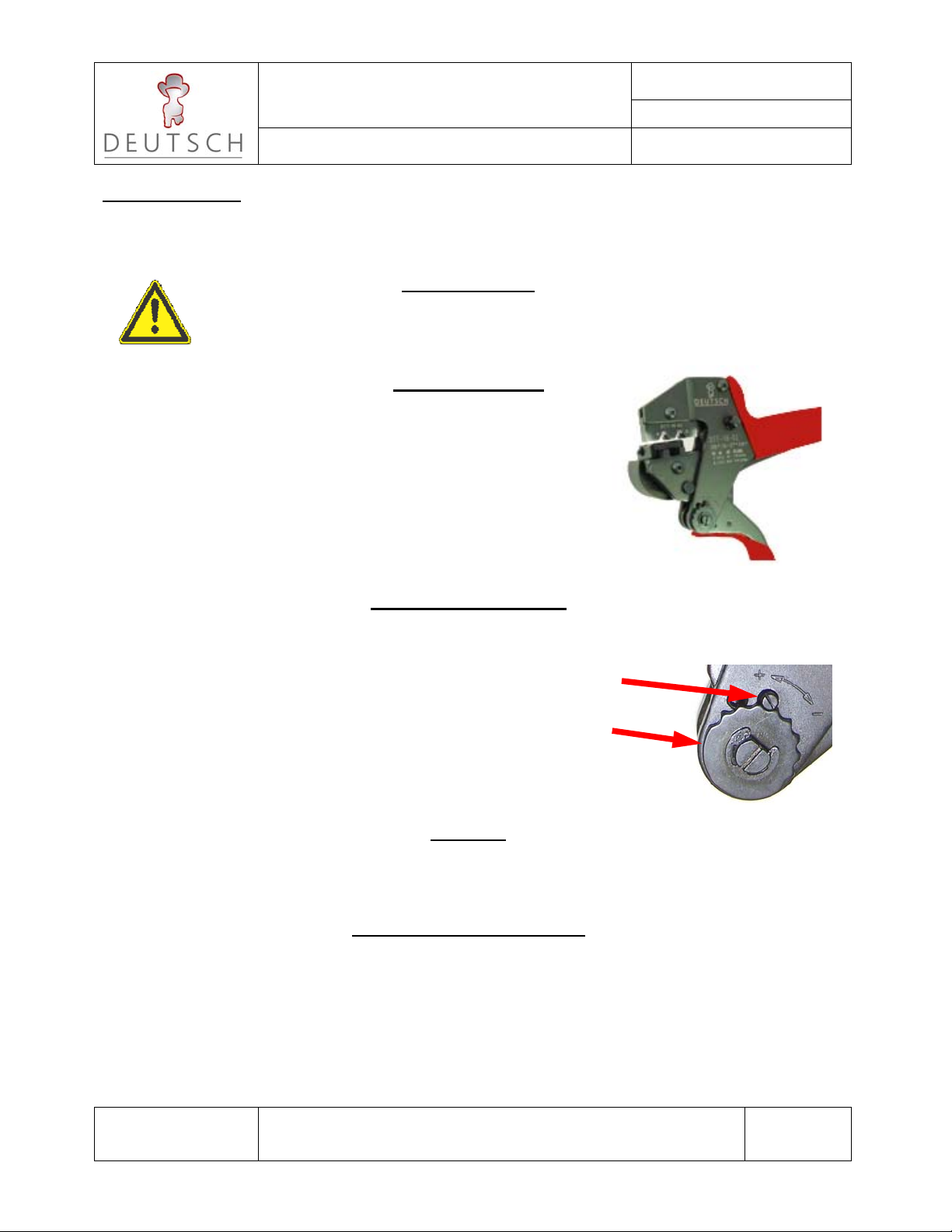
Hand Force Adjustment
Crimping Force of DTT-16-03 is factory set. Hand force idle travel is 130 N – 180 N. The tool and die
set are designed to provide optimum crimping within this range. However, if the setting is not ideal for
the contact specification, the tool can set as described below:
(1) Loosen the headless screw with a flat-blade screwdriver and set aside.
(2) Turn the adjustment wheel counter anticlockwise (+) to increase the
crimping force. (This also reduces the jaw spread).
(3) Turn the adjustment wheel clockwise (-) to reduce the strength of the
crimping force. (This also increases the jaw spread) Don’t exceed 180 N!
(4) After setting, replace the headless screw and adequately tighten.
Warranty
These tools are subject to thorough quality control measures before leaving the factory. The general
terms and conditions of warranty are available from Compagnie Deutsch GmbH.
Maintenance and Inspection
Maintenance and inspection should be performed after about 5,000 crimps (or every 6 months).
Before using the crimping tool make sure that it is in a clean and proper operating state. Remove any
crimping residue. Apply light machine oil to protect joints. Check bolts to ensure that the lock washers
are secure and intact. All other maintenance should be performed by the manufacturer. There are no
user-serviceable components inside the hand tool. Disassembly of the crimp tool shall void warranty.
Do NOT
close
handles
completely

INSTRUCTION MANUAL FOR
DTT-16-03
Date: August 11th, 2010
INFORMATION Drawing No: 0425-077-0000 Revision Letter: NC
Compagnie Deutsch GmbH
Fraunhoferstr. 11 b
D-82152 Martinsried Page 3 of 4
Recommended Cavity for wire Gauge and Insulation Types
Use Table 1 to insure best crimp results with DEUTSCH stamped and formed contacts of the types:
1060-16-12** PIN and 1062-16-12** SOCKET, or…..
1062-16-14** SLEEVELESS SOCKET (ref: 0425-039-0000 Information Drawing)
Table 1: Cavity, Wire size, and Insulation Types (note: Dimensions are in mm)
Stamped Contact
Part Numbers Nominal Insulation
Diameter Ranges Cavity
Rec. METRIC Wire
sizes Insulation Types
for AWG
1060-16-12** Pin
1062-16-12** Soc
1062-16-14** Soc
1.70 - 2.29 mm A 1.0 mm² 16 TXL
1.5 mm²
2.18 - 3.15 mm B 1.5 mm² 16 TXL, GXL
14 TXL, GXL
2.5 mm² 12 TXL
Dimensional Guide for Crimp Geometry development with Power-Press Applicator Dies*:
*Note: Hand-Tool crimps are NOT the same as Applicator Die crimps. Actual geometry will be
an approximation of the best-fit compromise within the 2-cavity tooling limitations,
and are significantly dependant on the tool OPERATOR skills and technique.

INSTRUCTION MANUAL FOR
DTT-16-03
Date: August 11th, 2010
INFORMATION Drawing No: 0425-077-0000 Revision Letter: NC
Compagnie Deutsch GmbH
Fraunhoferstr. 11 b
D-82152 Martinsried Page 4 of 4
REFERENCE Sizes in millimetres for sample crimps made per Table 1:
Table 2 Typical crimp dimensions (stop at ratchet-release)
Using conductor types per SAE J1128 and ISO 6722 (Metric)
Cavity
Wire
mm², AWG Insulation
Ø Nominal Conductor Insulation
Height Width Height Width
A
1.0 mm² 1.70 1.35-1.45 2.77 2.39-2.49 2.49-2.54
16 TXL 2.21 1.42-1.55 2.77-2.79 2.57-2.62 2.57-2.59
1.5 mm² 2.29 1.47-1.57 2.77 2.59-2.74 2.62-2.64
B
16 TXL 2.18 1.40-1.47 2.77 2.72-2.74 2.82-2.84
16 GXL 2.62 1.45-1.50 2.77 2.77-2.79 2.84-2.90
1.5 mm² 2.29 1.47-1.52 2.77-2.79 2.77-2.79 2.84
14 TXL 2.57 1.50-1.55 2.77-2.79 2.82 2.87-2.92
14 GXL 3.02 1.52-1.55 2.77-2.79 2.82-2.84 2.87-3.00
2.5 mm² 2.84 1.52- 1.57 2.79 2.84 2.92
12 TXL 3.15 1.60-1.70 2.79-2.84 2.92-2.97 3.07
Note: Check reference sizes after 5,000 crimps (or 6 months).
Visually inspect for loose hardware and broken or missing parts.
Measure conductor height with blade and point micrometer to prevent
false readings which might include crimp flash (burr).
Dimensions vary with different hand tools and operators. Closing handles
beyond ratchet release will reduce crimp height.
Table of contents
Other Deutsch Crimping Tools manuals


Popular Crimping Tools manuals by other brands

ABB
ABB T&B Tools TBM62CR-LI operating instructions

Milwaukee
Milwaukee M18 FORCE LOGIC 2977-20 Operator's manual

TECHMAFLEX
TECHMAFLEX PMC 32 user manual

Textron
Textron Greenlee RK1240 instruction manual

molex
molex 207129 Series Specification sheet

Tyco Electronics
Tyco Electronics 69156-1 instruction sheet


