HRS DF65 Series User manual

取扱説明書 /
INSTRUCTION MANUAL
手動圧着工具HT305 型
Manual crimping tools Type HT305
安全に使用していただくために使用前に、必ずこの取扱説明書をお読みください。
また、いつでもすぐに読めるように、この取扱説明書を保管してください。
注意
CAUTION :
Be sure to read this Instruction Manual carefully before using it to secure safe operation.
Save this Instruction Manual so that it is available whenever necessary.
ATAD-P0138第3版/
Third edition

はじめに
この度は、手動圧着工具をご購入いただき誠にありがとうございます。
ご使用前に必ず本書をよくお読みいただき十分ご理解の上、正しくご使用くださいますようお願い致します。
Forward
Thank you for purchase of our manual crimping tool.
For safe operation read, understand and follow this Instruction Manual.

i
安全にご使用していただくために
本工具を実際にご使用されるオペレータの方、および保守・修理などをされる保全の方は、以下の
安全についての注意事項を熟読されて、怪我などされないようにご使用ください。
なお、本取扱説明書および警告表示の内容を十分に理解し、指示を守ってください。
安全についての注意事項
ご使用される前に本取扱説明書、および付属に入っている全ての説明書類を必ずお読みください。また、いつでも
すぐに読めるように、この取扱説明書を大切に保存してください。
本工具には、安全カバーなどの安全装置は取り付いていません。圧着作業に際しては、ハンドル部に指など挟まな
いよう安全に十分配慮してご使用ください。
1. この工具は、本来の用途および本取扱説明書に規定された使用方法以外には使用しないでください。用途以外の
使用に対しては、当社は責任を負いません。
2. 工具には、改造などを加えないでください。改造によって起きた事故に対しては、当社は責任を負いません。
1. 不慣れによる事故を防ぐため、修理・調整は工具を熟知した保全技術者が本取扱説明書の指示範囲で行ってくだ
さい。不適切な修理・調整および非純正部品による事故に対しては、当社は責任を負いません。
2. 人身事故を防ぐため、修理調整・部品交換などの作業後は、ねじ・ナットなどがゆるんでいないことを確認して
ください。
3. 工具の使用期間中は、定期的に清掃を行ってください。
4. 事故を防ぐため、修理・調整した結果、正常に動かない場合は直ちに操作を中止し、当社に連絡し修理依頼して
ください。
注意
基本的注意事項
安全装置
用 途
保 守
FOR SAFE OPERATION
The operators of the tool and the maintenance personnel who are in charge of maintenance and repair work are required
to read the following SAFETY INSTRUCTIONS .
Fully understand and follow the descriptions given in this Instruction Manual and the warning symbols attached to the tool.
SAFETY INSTRUCTIONS
Basic safety instructions
Be sure to read understand and follow all the instructions and other materials supplied with the tool before use. Save this
Instruction Manual and make it available, when necessary.
Safe operation
Be sure to use the tool as instructed so that your fingers nor part of clothing is caught in the tool during crimping operation.
Application
1. This tool shall only be used for its originally intended purpose while following the instructions specified in this Instruction
Manual. Hirose assumes no responsibility for any misuse of the tool other than the intended use.
2. Modifications to this tool is prohibited. We assume no responsibility for accidents resulting from modifications.
Maintenance
1. To prevent possible accidents caused by unfamiliarity with the operation of the tool, repair and adjustment of the tool shall
be conducted only by fully trained maintenance personnel. Any repair and adjustment beyond the range covered by the
instructions given in this Instruction Manual is prohibited. We assume no responsibility for accidents caused by improper
repair or adjustment or the use of non-genuine part(s).
2. To protect against personal injury, assure that screws and nuts are properly tightened after the completion of repair/
adjustment works or replacement of the parts.
3. Periodical cleaning of the tool is recommended.
4. In the event that your tool fails to perform satisfactory after repair or adjusting immediately stop the work and contact HRS
for service.
CAUTION

ii
目 次
CONTENTS
1. 工具使用上の注意および保守....................1
2. 圧着作業基本要領........................................2
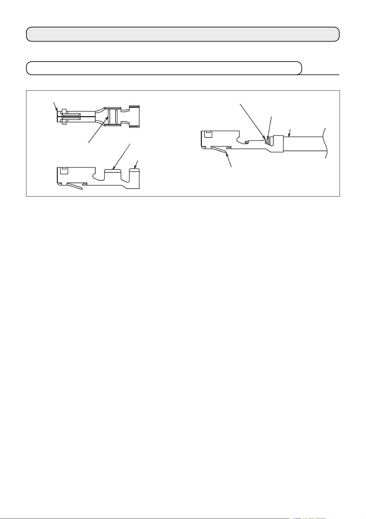
2-1. 圧着端子各部の名称および機能.................... 2
2-1-1. 圧着端子各部名称.......................................2
2-1-2. 圧着端子各部の機能...................................2
2-2. 電線被覆のストリップ................................... 3
2-2-1. ストリップ長さの適否...............................3
2-2-2. 電線ストリップ状態...................................3
2-3. ベルマウス....................................................... 3
2-4. クリンプハイト............................................... 3
2-5. 圧着部の引っ張り強度および測定方法........ 4
2-5-1. 圧着部引っ張り強度...................................4
2-5-2. 引っ張り強度の試験方法...........................4
2-6. 圧着後の端子形状の確認............................... 4
2-6-1. 良品の基準..................................................4
2-6-2. 圧着不良例..................................................5
2-7. 端子のハウジングへの挿入............................ 7
2-7-1. ランス高さの確認.......................................7
2-7-2. 組立手順(例)............................................7
2-7-3. ハウジング組立状態の確認.......................7
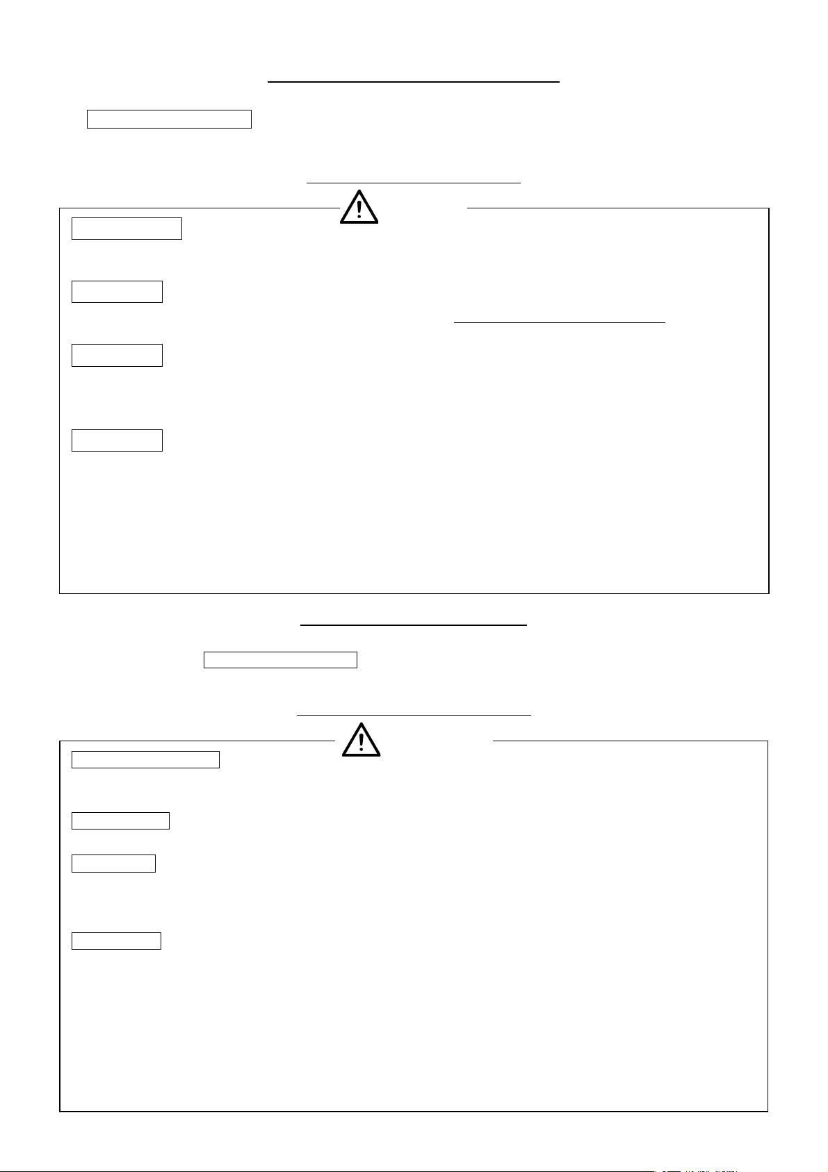
2-7-4. 端子の引き抜き方法...................................7
2-7-5. 組立後の確認..............................................7
2-8. その他、注意事項........................................... 8
2-8-1. 電線結束時の注意事項...............................8
2-8-2. 導通耐圧チェック.......................................8
2-8-3. 端子の取り扱い...........................................8
3.工具の外観および各部の名称....................9
4. 工具一覧表................................................ 10
5. 作業手順.................................................... 11
5-1. 圧着手順....................................................... 11
6. クリンパの交換方法................................. 12
7. 圧着条件および圧着品質基準................. 13
8. 圧着条件および圧着品質基準表.............. 14
1. Precautions in handling the tool
and maintenance .............................................1
2. Basic outline of crimp operation ...................2
2-1.
Configuration and function of crimp contact
... 2
2-1-1. Configuration of crimp contact ..................... 2
2-1-2. Function of each part of crimping contact ... 2
2-2. Stripping of wire outer insulation..................... 3
2-2-1. Correct stripping length................................. 3
2-2-2. Stripped wire condition.................................. 3
2-3. Bellmouth (flare) ................................................ 3
2-4. Crimp height....................................................... 3
2-5. Tensile strength of crimped section and
measuring method.............................................. 4
2-5-1. Tensile strength of crimped section............... 4
2-5-2. Testing method of tensile strength................. 4
2-6. Confirmation of the shape of contact after
crimping .............................................................. 4
2-6-1. Standards for acceptable crimp .................... 4
2-6-2. Example of defective crimping ...................... 5
2-7. Insertion of contact into housing ...................... 7
2-7-1. Checking the lance height .............................. 7
2-7-2. Assembling procedure (example) .................. 7
2-7-3. Checking the assembly condition
of the housing .................................................. 7
2-7-4. Contact extraction .......................................... 7
2-7-5. Verification of the complete contact
insertion ........................................................... 7
2-8. Other precautions............................................... 8
2-8-1. Precautions when tying the wire.................... 8
2-8-2. Connector continuity check ........................... 8
2-8-3. Handling of the contacts................................. 8
3. Configuration of the tool ................................9
4. Table of tools..................................................10
5. Operating procedures................................... 11
5-1. Crimping procedure..........................................11
6. Replacing the crimper .................................12
7. Crimping conditions and
crimping quality standard ...........................13
8. Table of crimping conditions and
crimping quality standard ...........................14

−
1
−
1.工具使用上の注意および保守 /Precautions in handling the tool and maintenance
図 1/Fig.1
ドライバー /
Flat blade
screwdriver
■ 使用上の注意
1 手動圧着工具は、クリンプハイトの微調整が行えませ
んので、端子の適合電線範囲であっても、ご使用にな
る電線が指定電線と異なる場合は、工具に適合しない
場合があります。
2 本書に示す適合端子・適合ケーブル以外の物を、絶対
圧着しないでください。
3 工具を叩いたり、高い所から落とすなどの衝撃は、絶対加えないでください。
4 工具には適正な加圧が行われるまで、ハンドルが開かないようにラチェット機構が備わっています。
ラチェットが解除する前に、ハンドルを開くことはできません。無理に開いたりすると工具が故障しますので、絶
対しないでください。
5 ラチェットが解除した後もハンドルに過度な荷重をかけ続けますと、ハンドルが閉じたまま開かなくなることがあ
ります。その際は、図 1 のようにドライバーなどをハンドルに入れ開いてください。
また、過度な荷重をかけることはハンドツールのガタを引き起こし、正常な圧力が得られなくなる原因になります
のでご注意ください。
6 作業を始める時は、圧着した端子の圧着状態が良品の範囲になっているか確認を行ってください。
■ Handling precautions
1 The tools can not be adjusted for crimp height or configuration. Only specified wire size, construction and type must be used
with the applicable contact and tool.
2Do not crimp other than the specified contact or wire.
3Do not subject the tool to physical impact or drop.
4Do not attempt to release the moveable handle before completing full compression as this may damage the tool. Handle will
release after completion of the full compression. The handle can not be opened before automatic release of the ratchet.
5Do not apply excessive compression on the handles after full compression. Occasionally the moveable handle may remain closed
after the full compression. Insert a flat blade screwdriver (or similar tool) as shown on illustration above (Fig. 1), to release it.
In addition, applying an excessive compression can produce a play in the hand tool. With the hand tool with a play, the normal
pressure cannot be obtained. So, be careful.
6Assure that the crimp condition after the termination with the wire is within specification.
■ 保守と点検
【日常のお手入れについて】
1 作業が終了した場合は、汚れ・異物などを柔らかい布で拭き取りハンドルを閉じクリンパ・アンビルの中に異
物が入り込まないようにして、乾燥した場所に保管してください。
2 ハンドル開閉の際、アンビルがカジリなどなく滑らかに摺動することを確認してください。
【定期メンテナンスについて】
弊社では、ご使用中の工具が適正な状態にあるかを判断するメンテナンスを行っています。
メンテナンスをご希望される際は、弊社営業所または購入された代理店にご依頼ください。
【工具の修理について】
工具に不具合が生じ修理を希望される時は、解体などせずそのままの状態で、不具合内容を明示の上、弊社営業所
または代理店へお申し付けください。
不具合の内容によっては修理しかねる場合もありますので、予めご承知おきください。
■ Maintenance and inspection
【Routine maintenance】
1Upon completion of work wipe the tool with a soft cloth to remove any stains or foreign particles, specially in the crimper
and anvil areas.
2Close the handles making sure that the crimper and anvil slide smooth, without any interference. Store in the dry place.
【Routine maintenance】
HRS offers maintenance service to evaluate condition and performance of the tool.
Request this service from the place of purchase or the nearest HRS representative.
【Repair of the tools】
Contact the place of purchase or nearest HRS representative. Describe exact nature of the problem. Do not diss-assembly the
tool. If instructed, ship the tool in a secure package, with a written description of the problem.
HRS does not sell individual components for the tools.
Depending on it’s condition in some cases the tool may NOT be repairable.
工具 /Tool

−
2
−
2.圧着作業基本要領 / Basic outline of crimp operation
圧着作業の基本的な一般事項について説明します。
General description of the crimp process.
2-1.圧着端子各部の名称および機能 /Configuration and function of crimp contact
1ワイヤーバレル(芯線圧着部)....
U字形状で機械的な力により、導線を加締め保持して端子と接続する役目を持ちます。
ワイヤーバレルの大きさにより、適合する電線の範囲が決められます。
適合外の電線を圧着すると、所定の性能が得られず品質上重大な事故を起こすこと
があります。
2
インシュレーションバレル .........
電線の被覆を加締めるバレルで、電線に負荷がかかった際にワイヤーバレル部で導
線が断線しないように電線を保持する機能を持ちます。
3ランス ........................................... 端子をハウジング(絶縁ケース)に挿入した際端子を、ハウジングから抜けないよ
うに固定するロック機構の役目をします。
ランスが変形していますと、ハウジングに挿入した後ロック機構が機能せず、端子
がハウジングから抜けてしまったり、所定の固定力が得られないことがあります。
4ベルマウス ................................... バレル端面での断線の防止と、圧着部の引っ張り強度の安定を目的として設けてい
る物です。
5セレーション ............................... ワイヤーバレルの内面に平目や綾目の凹みを設けることが有り、これをセレーショ
ンと呼びます。
セレーションは圧着時にバレル面と導線の酸化皮膜の破壊を助長し、より電気的・
機械的に接続の安定を狙うものです。
6コンタクト部 ...............................
コネクタの雄と雌を嵌合させた時、相手側のコンタクトと電気的に接合する部分です。
2-1-2. 圧着端子各部の機能 /Function of each part of crimping contact
1Wire barrel
........................
(conductor crimp section)
U-shaped section of the contact which is compressed around the conductors with a mechanical force.
Configuration and dimensions after the completion are critical for maintaining mechanical and electri-
cal performance of the contact.
2Insulation barrel
...............
U-shaped section of the contact which is compressed around the outer insulation of the wire. Its func-
tion is to act as a strain relief, preventing transmission of any pull force on the wire to the conductor
crimp section.
3Lance..............................
(contact retention tab)
Retains the contact in the applicable insulator (socket). Any deformation of the lance may prevent
retention or extraction of the terminated wire from the insulator body (socket).
Note : Some contacts may NOT have lance and be retained in their respective housings by other
means.
4Bellmouth (flare)............. Critical configuration of the crimp section of the contact whose function is to avoid breakage of the
terminated conductor and assure strength of the crimp.
5Serrations........................ Deformations or cross-serrations of the material inside the wire barrel whose function is to break pos-
sible oxidation films on the contact and conductors during the crimping, thus assuring stable electrical
connection.
6Contact section................ Configuration of the contact which will make electrical and mechanical connection with the corre-
sponding mating contact.
2-1-1. 圧着端子各部名称 /Configuration of crimp contact
インシュレーションバレル /
Insulation barrel
ベルマウス /Bellmouth
芯線 /
Conductor
被覆/
Outer insulation
ランス /Lance (retention tab)
セレーション /
Serrations
コンタクト部分 /Contact section
ワイヤーバレル /
Wire barrel

−
3
−
2-3.ベルマウス /Bellmouth (flare)
2-2.電線被覆のストリップ /Stripping of wire outer insulation
2-2-1. ストリップ長さの適否 /Correct stripping length
電線のストリップ長さは、端子ごとに設定されています。ストリップ長さの加工精度により、圧着の作業性品質が
左右されますので注意してください。
Stripping length of the wire is specified for each contact. Correct crimping depends on accurate stripping of the wire.
根元に傷をつけない /
Do not damage any
individual strands
a
a:ストリップ長さ
a : Stripping length
適正なストリップ長さ:圧着した際、ワイヤーバレル先端
から芯線が突き出しており、また被覆がインシュレーショ
ンバレルより引っ込んでいたりシールドバレル内に入り込
んだりしていない状態であること。
Correct stripping length: After crimping the conductors should
protrude from the top end of the Wire barrel and the Insulation
barrel should be around the Outer insulation, as shown on the
illustration on the left. Before crimping do not pull on the outer
insulation or attempt to insert it in the Wire barrel.
2-2-2. 電線ストリップ状態 /Stripped wire condition
芯線突き出し /Conductor juts out
圧着を行った端子は、後部にベルマウスがあることを確認してくださ
い。
ベルマウスの大きさは、端子により異なります。ベルマウスがないと、
ワイヤーバレル端面での芯線の断線や、圧着部の引っ張り強度不足と
なる恐れがあります。ベルマウスが大き過ぎる時は、電気的接続が不
安定となったり、圧着部の引っ張り強度不足となる恐れがあります。
Bellmouth must be present at the rear of the conductor crimped section and must be within the specified dimensions.
Size of it varies with each contact style. Absence of the bellmouth may cause conductor breakage and will affect the tensile
strength of the crimp. Excessive bellmouth may indicate insufficient tensile strength of the crimped section of the contact and
affect the electric connection.
1 芯線に傷がないこと。また一部が断
線したり脱落していないこと。
2芯線
の長さ、被覆切断端面がバラつい
ていたり、バラけていたりしないこと。
1Conductor should be free from any dam-
age or partially broken or missing strands.
2The conductor and outer insulation cut-
off’s must be straight. The outer insulation
can not be loose.
被覆切断端面 /
Incorrect stripping
芯線の長さ /
Length of the strand
2-4.クリンプハイト /Crimp height
クリンプハイトは、圧着端子の圧着品質を決める重要な要因です。
クリンプハイトが規格から外れている場合は、品質上の重大な事故を起こす恐れがあります。手動圧着工具の場合、
端子の適合電線範囲内であっても、工具にはご使用になる電線が適合しない場合がありますのでご注意ください。
Crimp height is critical factor in determining the correct crimp condition and must be as specified.
Specified wire size, construction and style must be used. The crimp height requirement may not be applicable with some wires
although they may be within the specified dimensions.
*クリンプハイトの測定には、クリンプハイト測定用マイクロメーターをご使用ください。
* Use the micrometer for measuring the crimp height.
マイクロメーター ( アンビル )/
Micrometer (anvil)
マイクロメーター ( スピンドル )
バレルのほぼ中央で測る /
Micrometer (spindle)
Measure near the center of the barrel.
クリンプハイト ( 被覆 )/
Crimp height
(outer insulation)
Yes No
後部ベルマウス /Bellmouth
クリンプハイト ( 芯線 )/
Crimp height
(conductor)

−
4
−
2-5.圧着部の引っ張り強度および測定方法 /
Tensile strength of crimped section and measuring method
2-5-1. 圧着部引っ張り強度 /Tensile strength of crimped section
芯線圧着部(ワイヤーバレル部)の電線を引っ張った時に耐えられる強さのことで、端子毎・電線毎に許容値を設
定しています。
Retention strength of the crimped wire when the pull force (N) is applied to it. The pull force is defined for each style of the
contact.
2-5-2. 引っ張り強度の試験方法 /Testing method of tensile strength
インシュレーションバレルが機能しないように、電線を長めにストラップしたものを圧着し、引っ張り試験機に取
り付け、電線が破断した時の値を測定します。(電線の引っ張り速度は 20mm 〜 80mm/ 分に設定してください。)
Secure the crimped contact on applicable fixture assuring that the wire can be freely pulled and the force can be measured.
Apply pull at the rate of 20 to 80 mm per minute until the failure of the crimp section (wire pulled-out). The value of the pull-out
force must be higher than the minimum specified.
2-6.圧着後の端子形状の確認 /Confirmation of the shape of contact after crimping
2-6-1. 良品の基準 /Standards for acceptable crimp
* 規格値については「8. 圧着条件および圧着品質基準表」を参照のこと。
* See " 8. Table of crimping conditions and crimping quality standard" for the specified values.
1 クリンプハイトが規格内にあること。
2 ベルマウスが適正な大きさであること。
3 芯線の突き出しは適正であること。
4 ワイヤーバレルに被覆の食い込み(深打ち)となっていないこと。
5 被覆はインシュレーションバレルに適正に圧着されていること。
6 芯線がワイヤーバレルからはみ出していないこと。
7 端子のコンタクト部に変形がないこと。
8 ランスに変形がないこと。
9 ワイヤーバレル部に大きなバリがないこと。
!0 圧着部に亀裂やバレル外面の肌に荒れがないこと。
!1 端子の曲りが「8. 圧着条件および圧着品質基準表」の規格を満足していること。
1The crimp height is in the specified range.
2The bellmouth has an is correct size.
3 The protrusion of the conductor is correct.
4The outer insulation is inserted in the conductor barrel.
5
The
outer insulation
is correct crimped in the insulation barrel.
6The conductor does not protrude from the wire barrel.
7The contact section of the contact is not deformed.
8The lance is not deformed.
9 The wire barrel has no noticeable burr.
!0The finished crimped section is free from any material crack or rough surface on the outside of the barrel.
!1 The bend angle in the contact is as specified in " 8. Table of crimping conditions and crimping quality standard".
2ベルマウス / Bellmouth
4 5被覆位置 / Position of outer insulation
3芯線位置 /
Protrusion of conductor
7端子コンタクト部 /
Contact section of contact
⑧ランス /Lance
1芯線部クリンプハイト /
Contact conductor section
of crimp height
!0 肌荒れ / Rough surface
1被覆部クリンプハイト /
Outer insulation section
of crimp height
9バリ/Burr

−
5
−
電線のストリップ寸法が不適切な時や、工具への電線のセットの仕方
により、発生することがあります。
深打ちにより、芯線の断線となる恐れがあります。
Caused by incorrect stripping of the wire or it’s positioning in the crimping
section of the tool. Conductor can be broken.
芯線が見えない /Conductor is invisible.
電線のストリップ寸法が不適切な時に、発生することがあります。
芯線の挿入不足により、引っ張り強度の不足や、電気的接続の不安定
となる恐れがあります。
Caused by incorrect wire stripping. Can cause conductor break, low pull-out
force or electrical connection failure.
2 深打ち /Insulation bulge or protrusion
3 芯線の挿入不足 /Partial insertion of the conductor
芯線が見えない /Conductor is invisible.
電線のストリップ寸法が不適切な時や、工具への電線のセットの仕方
により発生することがあります。
浅打ちにより芯線への負荷が直接に芯線圧着部に伝わり、断線となる
恐れがあります。
Caused by incorrect wire stripping. Can cause conductor break, low pull-out
force or electrical connection failure.
4 浅打ち /Insufficient compression of the crimp sections
被覆が見えない /Outer insulation is not visible.
電線のストリップ寸法が不適切な時や、工具への電線のセットの仕方
により発生することがあります。
突き出しが長過ぎることにより、コンタクトの接触障害となったりハ
ウジングへの挿入不完全となる恐れがあります。
Caused by incorrect stripping of the wire or it’s positioning in the crimping
section of the tool. Can cause failure of the connection or interfere with the
insertion of the terminated contact in the corresponding insulator (socket).
5 芯線の突き出しが長過ぎる /Too long protrusion of the conductor.
芯線が長すぎる /Too long
6 芯線はみ出し /Loose strands of the conductor.
芯線はみ出し /Loose 芯線がバラけたままの電線を使用すると、発生することがあります。
芯線のはみ出しにより、電気的接続の不安定となったり、引っ張り強
度の不足となる恐れがあります。
Caused by the loose conductor in the wire.
Can cause erratic electrical connection and loss of wire retention in the
crimp sections of the contact.
7 端子変形(ベントアップ・ダウン)/Deformed contact (Bent UP / DOWN)
工具の調整状態や摩耗、端子の工具へのセット状態、端子の取り扱い
により、発生することがあります。ベントアップ・ダウンが著しいと、
ハウジングへの挿入が行えないことがあります。
Can be caused by the wear of the tool, positioning of the contacts in the
crimping sections of the tool or handling of the contact.
Excessive angle will prevent insertion of the contact in the corresponding
insulator (housing).
アップ /
UP
ダウン /
DOWN
2-6-2. 圧着不良例 /Example of defective crimping
工具の調整状態や、工具への端子のセットの仕方により、発生するこ
とがあります。ベルマウスがなかったり大き過ぎることにより、芯線
の断線や引っ張り強度の不足、電気的接続の不安定となる恐れがあり
ます。
Caused by incorrect positioning of the contact in the crimping section of the
tool. Can cause conductor break, low pull-out force or electrical connection
failure.
1 ベルマウスなし、過大 /None or excessive bellmouth
ベルマウスなし /
No bellmouth.
ベルマウス過大 /Excessive bellmouth.

−
6
−
9 端子変形(ローリング)/Deformed contact (Rolling)
工具の調整状態や歯型の摩耗、工具への端子のセット状態、端子の取
り扱いにより、発生することがあります。ローリングが著しいと、ハ
ウジングへの挿入が行えないことがあります。
Can be caused by the wear of the tool, positioning of the contacts in the
crimping sections of the tool or handling of the contact.
Excessive deformation of the contact will prevent insertion in the corre-
sponding insulator (housing).
ローリング /
Rolling
!0 インシュレーションバレルの変形(キックバック)/Deformed insulation barrel (Kickback)
工具に適合しない電線を使用した時に、発生することがあります。
キックバックが著しいと、ハウジングに挿入した後ハウジングから
端子が露出し、耐圧上の問題となることがあります。
Caused by the use of incorrect wire or contact.
Excessive protrusion may expose part of the contact after insertion in the
corresponding insulator (housing) and may cause electrical shorts.
キックバック /Kickback
!1 芯線圧着部アンビル痕の不均一 /Uneven anvil indentation
アンビルの摩耗などで、発生することがあります。
アンビル痕が不均一ですと、電気的接触が不安定になること
があります。
Caused by the wear of the anvil side of the tool.
Can cause degradation of the electrical connection.
!2 圧着面の傷・打痕 /Damage or nicks on the crimp’s outer surfaces.
クリンパに傷や摩耗がある時、発生することがあります。
圧着面に傷や打痕がありますと、端子の変形やメッキ剥がれなどが発
生することがあります。
Caused by damage or wear of the crimp sections of the tool.
Can cause deformation of the contact, cracks or peels of the material.
傷・打痕 /Damage or nick
!3 圧着バリの過大、左右不均一 /Too large or irregular crimping burr
工具の調整状態やクリンパ・アンビルの摩耗・傷がある時、発生することがあります。
バリが著しかったり著しく左右が不均一なことにより、バリ部での端子の亀裂や電
気的接続の不安定,強度不足,端子の変形となる恐れがあります。
Caused by damage or wear of the crimp sections of the tool.
Can cause deformation of the contact, cracks or peels of the material, degradation
of the electrical connection or loss of the wire retention.
8 端子変形(ツイスト)/ Deformed contact (Twist)
工具の調整状態や、工具への端子のセット状態、端子の取り扱いによ
り、発生することがあります。ツイストが著しいと、ハウジングへの
挿入が行えないことがあります。
Can be caused by the wear of the tool, positioning of the contacts in the
crimping sections of the tool or handling of the contact.
Excessive deformation of the contact will prevent insertion in the corre-
sponding insulator (housing).
ツイスト /
Twist
マイクロメーター
( スピンドル )/
Micrometer (spindle)
アンビル痕が不均一 /
Uneven anvil indentation
良品/
Good product
均一なアンビル痕 /
Even anvil indentation
マイクロメーター
( アンビル )/
Micrometer (anvil)
バリ /Burr

−
7
−
2-7.端子のハウジングへの挿入 /Insertion of contact into housing
圧着した端子のランスの高さが、所定の寸法内にあるか確
認してください。
Lance height must be as specified on applicable drawing.
2-7-2. 組立手順(例)/Assembling procedure (example)
1) 端子より 10cm 以内の電線の部分をつかみ、挿入を
行ってください。
2) 端子は、ハウジングに対して水平となるように挿入し
てください。
3) 挿入中は端子を途中で止めず、ランスが掛かるまで
完全に行ってください。ランスが掛かった時は、「パ
チッ」という音と手応えがあります。
1) Hold the terminated wire within 10cm of the end of the
crimped contact.
2) Orient the contact lance as shown on illustration on the left
and align it with the housing.
3) Insert it until the lance is fully engaged, confirmed with an
audible sound.
10cm
2-7-3. ハウジング組立状態の確認 /Checking the assembly condition of the housing
良/
Good
挿入不足 / Inadequate insertion
ランスがハウジングの角窓に引っ掛かっているもの。
端子が矢印方向に若干ガタがあり、浮遊性がある。
The lance is properly engaged in the rectangular opening in the housing.
The contact is moving in direction of the arrow (float), as illustrated.
挿入不足 ( 角窓からランス全体が見えない )。
Partial insertion. Lance is not engaged in the rectangular opening.
ランス変形 ( ランスが角窓に引っ掛かっていない )。
The lance was deformed and did not engage in the rectangular opening.
2-7-4. 端子の引き抜き方法 /Contact extraction
端子のハウジングからの引き抜き方法は、コネクタにより異なります。端子の抜き治具が、専用で用意されている
ものもあります。詳細は、コネクタのカタログなどで確認を行ってください。
Contact extraction procedure varies with a specific connector insulator (housing).
Specific extraction tools are listed in applicable catalogs.
2-7-5. 組立後の確認 /Ve r ification of the complete contact insertion
1) ハウジングに端子が正しく組込まれていることを確認
してください。
2) 電線を軽く手で引っ張り、端子が抜けないことを確認
してください。
1) Verify visually that the lance is fully engaged in the rectangular opening.
2) Apply slight pull force on the wire in the direction shown on the illustration and verify that the contact can not be pulled-out.
ランス高さ /
Lance height
挿入不足 / Inadequate insertion
2-7-1. ランス高さの確認 /Checking the lance height
水平に引く /
Pull direction

−
8
−
2-8.その他、注意事項 /Other precautions
2-8-1. 電線結束時の注意事項 /Precautions when tying the wire
電線を結束する際は、電線に余裕を持って行い、端子に直接負荷が掛からないように注意してください。
電線の両端を結束する際は、最初に結束した側の端子に負荷が掛からないように注意してください。
Make an allowance for the wire when tying the wire so that an extra load is not applied to the contact.
When tying both ends of the wire, be careful that any load is not applied to the contact on which the wire is tied first.
2-8-2. 導通耐圧チェック /Connector continuity check
結線品の電気検査を行う際は、相手側コネクタなどに嵌合した状態で行ってください。
端子接触部に異物を挿入したりしますと、コンタクト部が変形し導通不良となる恐れがあります。
When performing this test make sure that the tied wires do not interfere with the mating with the corresponding part.
Do not insert any test probes or other pins into the socket contact as it may damage it, causing electric discontinuities.
2-8-3. 端子の取り扱い /Handling of the contacts
1 端子には必要以上に触れないでください。
2 端子に触れる際は、腐蝕防止のためなるべく手袋などを着用してください。
3 端子の上に物を置いたり、端子を落下しますと変形しますので、乱暴な取り扱いはしないでください。
4 端子が絡んだ時は、無理に引っ張ったりせず、変形させないように慎重にほぐしてください。
5 端子をつまむ時は軽くつまみ、ランスやコンタクト部など変形しやすい所はつままないようにしてください。
6 圧着が完了した電線は、端子同士が絡まないように注意し、束ねたり重ねる場合は、端子に外力が掛からない
ように注意してください。
7 端子は腐蝕防止のため、ポリ袋などに入れて保管してください。
1Do not handle the wires more than is necessary.
2When touching the contacts wear appropriate gloves to avoid corrosion causing contamination.
3Do not place any object on the contacts or drop it.
4Avoid tangling of the terminated wires. Should the wires become tangled handle the contacts with extreme care to avoid any
deformation.
5Do not handle contacts in the lance or contact areas. Any deformation in these areas will affect performance.
6Do not entangle the contacts with each other.
7Store the terminated wires in a non-corrosive environment.

−
9
−
3.工具の外観および各部の名称 /Configuration of the tool
製品名表示 /
Tool number
製造番号表示 /
Serial number
可動ハンドル /
Moving handle
製造年月日 /
Date of manufacture
抜き差しピン /Release pin
232±5
(110)
固定ハンドル /
Stationary handle
55±5
28±2
適合電線 AWGNo. 表示 /
Marking of applicable wire AWG No.
適合端子名表示 /
Marking of applicable contact
クリンパ /Crimper
クリンパ /Crimper
アンビル /Anvil
適合電線 AWGNo. 表示 /
Marking of applicable wire
AWG No.
キャリアカッター /
Carrier cutter
電線押え /Cable stopper

−
10
−
No.
工具製品番号
Tool number
工具
HRS 製品コード
HRS tool No.
適合端子
Applicable con-
tact No.
適合端子
HRS 製品コード
Applicable HRS
contact No.
工具標準適合電線 /Standard applicable wire for tool
STYLE No. AWG No. 計算断面積 (mm2)
Sectional area (mm2)
被覆外径
Outside diameter of
the outer insulation
1 HT305/DF57-2830HC 902-4635-0 DF57-2830SCF 666-0001-4 UL1571
( 細線タイプ /
Thin wire type)
28 〜30 0.057 〜0.089
0.50 〜0.63
2 HT305/DF50-2830HC 902-4634-8 DF50-2830SCFA 665-0002-0 UL1061 28 〜30 0.0571 〜0.0887
0.80 〜0.88
3 HT305/DF61-2226S 550-0304-2 DF61-2226SCF 666-5004-0 UL10368 22 〜26 0.141 〜0.342
0.98 〜1.26
4 HT305/DF61-2628S 550-0305-5 DF61-2628SCF 666-5005-2 UL10368 26 〜28 0.089 〜0.141
0.88 〜0.98
5 HT305/DF65-2428S 550-0306-8 DF65-2428SCF 666-6003-2 UL10368 24 〜28 0.089 〜0.221
0.88 〜1.11
4.工具一覧表 / Table of tools

−
11
−
1) 工具の HRS マーク、製品名表示側を上に向けて持っ
てください。
2) ハンドルを最後まで握りラチェットを解除させ、ハン
ドルを最大に開いてください。
3) 端子をリールから約 10cm 位に切断し、レバーを下
げながら工具の端子ガイド部に通します。
端子の 1 ピン目がアンビル上に到着したことを確認
し、端子キャリア部の丸穴に位置決めピンを合わせた
ら、レバーを離してください。
(注意) 変形した端子は通りません。使用しないでください。
端子を通すと、「カチ」と手応えがあります。端子が
アンビル上に来た時「カチ」と手応えがあった位置
が圧着位置です。
1) Hold the tool with HRS logo and HRS tool number facing
up.
2) Compress the handle until the moving handle releases and
is fully open.
3) Cut the contact from the reel in the length of about 10
cm, and insert the contact into the contact guide of the
tool while lowering the lever.
Confirm that the first pin of the terminal arrived on the
anvil, and release the lever when the locating pin align
with round hole of career.
(Caution) The deformed contact cannot be passed. Do not use
it. When the contact is passed, there is a response
of "click". The position where there is a response of
"click" when the contact comes on the anvil is the
crimping position.
注意 操作中、手への損傷防止のため、ハンドルの間や圧着部に指を入れないでください。
CAUTION :
To prevent injury, do not place the fingers between the handles or crimping sections.
5.作業手順 /Operating procedures
5-1.圧着手順 /Crimping procedure
HRS マーク表示 /
HRS logo
製品名表示 /
HRS tool number
抜き差しピン /
Release pin
端子ガイド /
Contact guide
キャリア
カッター /
Carrier
cutter
端子 /Contact
レバー /Lever
キャリアの丸穴に位置決めピンを合
わせる /
Align the locating pin with round hole
of career.
キャリアの丸穴 / Round hole of career
ケーブルストッパー /
Wire stopper

−
12
−
4) 所定の長さに被覆をストリップしたケーブルを、芯線
が解かれないように端子の位置に合わせてください 。
(被覆ストリップ長さは「8. 圧着条件および圧着品質
基準表」をご参照ください。)
(注意) 圧着不良となる可能性がありますので、ケーブルで
直接端子を押さないでください。
5) ハンドルをラチェットが解除するまで握ります 。
6) ラチェットが解除するまで握ると、ハンドルは開きま
す。
7) 圧着された端子を、ケーブルを持って引き出してくだ
さい 。
(注意) 端子をケーブルストッパーなどに当てて変形させな
いように注意してください。
8) 正規に圧着されたかを確認してください 。(「8. 圧着
条件および圧着品質基準表」をご参照ください 。)
4) Strip the covering of the cable by a given length. Then
match the cable to the position of contact while taking care
not to allow the contact wire to loosen. Refer to “8. Table of
crimping conditions and crimping quality standard” for the
stripping dimensions.
(Caution) Do not press the contact directly with the cable since
there is a possibility of defective crimping.
5) Grab the handle by hand until the ratchet is released.
6) Grab the handle by hand until the ratchet is released and the
handle is opened.
7) Draw out the crimped contact while holding the cable.
(Caution) Be careful not to allow the contact to hit against the
cable stopper, etc. to deform.
8) Verify the crimp correct dimensions refer to paragraph “8.
Table of crimping conditions and crimping quality stan-
dard”.
( 圧着部拡大図 )/
(Enlarged view of the crimping section)
ケーブルストッパー /
Wire stopper
ケーブル /Wire
キャリアカッター /
Carrier cutter
端子 /Contact
( 圧着部拡大図 )/
(Enlarged view of the crimping section)
6.クリンパの交換方法 /Replacing the crimper
手動圧着工具は 、 ご使用になるケーブルサイズによりクリンパを交換してご使用ください 。( アンビルは共用です 。)
Crimp side of the tool can rotated as shown on the illustration below to fit the wire gage used. Anvil side is stationary and can not be
removed.
1) 圧着工具ヘッド部にある抜き差しピンを引き抜いてく
ださい 。
2) 矢印方向にクリンパを引き抜いてください 。
3) クリンパを 180˚回転させ 、 ご使用になるケーブルサ
イズの刻印表示が見えるように取り付け 、 抜き差しピ
ンを差し込んでください 。
( 注意 ) 工具によってはクリンパを交換する場合もあります。
1) Withdraw the releasing pin.
2) Withdraw the crimper in the direction shown by the arrow.
3) Rotate the crimper 180° and re-insert in the tool, showing
the marking of the applicable wire gage used. Re-insert the
releasing pin.
(Caution) Some crimpers used in this tool may be non-rotating.
Replacement procedure will not require rotating 180°.
180˚回転させる/
Turn the crimper by 180˚
抜き差しピン/
Release pin
キャリア /
Carrier
落下 /Drop

−
13
−
7.圧着条件および圧着品質基準 /Crimping conditions and crimping quality standard
1) 本工具により圧着した端子のクリンプハイトおよび引張り強度が、「8. 圧着条件および圧着品質基準表」の規格を
満足しているかをご確認ください。
2) 本工具により圧着した端子の形状が、良品の基準にあることをご確認ください。
( 注意 )1. 標準電線と異なる被覆径の電線をご使用の際は、弊社営業または代理店様にご相談ください。
2. 下図は端子形状の一例です。各部名称の参考にしてください。
1) Check to be sure that the contact that has been crimped using the tool satisfies the standard described in “8. Table of crimping
conditions and crimping quality standard" with respect to the crimp height and the tensile strength.
2) Check to be sure that the contact that has been crimped using the tool is within the standard of good product with respect to the
shape.
(Caution) 1. To use a wire a covering diameter of which is different from that of the standard wire, please contact our Business
Division or the distributor in your area.
2. The figure below is an example of the shape of contact. Use the figure for reference of configuration.
ストリップ長さ /
Strip length
ツイスト/Twist
圧着バリ高さ /
Crimping burr height
ローリング /
Rolling
圧着部断面 /Wire barrel section
ワイド:ワイヤーバレル /
Wide : Wire barrel
被覆部断面 /Insulation barrelsection
ワイド:
インシュレーションバレル /
Wide : Insulation barrel
ランス高さ /
Lance height (if applicable)
ベルマウス /
Bellmouth
ベントダウン /
Bent DOWN
ベントアップ /
Bent UP
芯線先端位置 /
Protrusion of the conductor
芯線クリンプハイト /
Conductor crimp height
被覆クリンプハイト /
Outer insulation crimp height
被覆位置 /
Covering position
カットオブタブ /
Cut of tub
ギャップ寸法 /
Gap dimension

−
14
−
工具
製品番号
Tool No.
適合端子
Applicable
contact No.
電線
ストリップ
寸法
Stripping
dimension
of wire
標準適合電線
Standard applicable wire
クリンプハイト
Crimp height
引張強度
Pull force
圧着品質基準
Crimping quality standard
STYLE No. AWG
No.
芯線構成
Structure
of the
conductor
被覆外径
Outside di-
ameter of
the outer
insulation
(芯線)
(Con-
ductor)
(被覆)
(Outer
insulation)
(N) 以上
(N) or more
項目
Item
被覆
位置
Outer in-
sulation
position
芯線先端
位置
Protrusion
of the
conductor
ベル
マウス
Bell-
mouth
ベント
アップ
Bent
UP
ベント
ダウン
Bent
DOWN
ツイ
スト
Twist
ローリ
ング
Rolling
ランス
高さ
Lance
hight
カット
オブ
タブ
Cut of
tub
スト
リップ
長さ
Strip
length
圧着バ
リ高さ
Crimping
burr
hight
ワイド
Wide
ギャッ
プ寸法
Gap
dimen-
sion
圧着部
Wire
barrel
section
被覆部
Insulation
barrel
section
1
HT305/
DF57-
2830HC
DF57-
2830SCF
UL1571
撚線
(細線
タイプ)
Stranded
wire
(Thin wire
type)
28 7/0.127 Ø 0.58
0.44
〜
0.48 0.75
〜
0.85
16 寸法
Dimen-
sion
0.1
〜
0.4
0.1
〜
0.4
0.1
〜
0.2
3˚
MAX
2˚
MAX
±3˚
MAX
±4˚
MAX
0.05
MAX
1.0
〜
1.4
0.05
MAX
0.97
MAX
0.02
〜
0.09
30 7/0.102 Ø 0.56
0.40
〜
0.44
8
2
HT305/
DF50-
2830HC
DF50-
2830SCFA UL1061
28 7/0.127 Ø 0.88
0.46
〜
0.50
1.20
〜
1.30
16 寸法
Dimen-
sion
0.1
〜
0.5
0.1
〜
0.5
0.1
〜
0.25
3˚
MAX
3˚
MAX
±3˚
MAX
±4˚
MAX
0.05
MAX
1.3
〜
1.7
0.05
MAX
0.78
MAX
0.005
〜
0.06
30 7/0.102 Ø 0.80
0.42
〜
0.46
1.10
〜
1.20
8
3
HT305/
DF61-
2226S
DF61-
2226SCF UL10368
22 17/0.16 Ø 1.26
0.68
〜
0.72
1.55
〜
1.65
40
寸法
Dimen-
sion
0.1
〜
0.5
0.1
〜
0.4
0.15
〜
0.3
2˚
MAX
3˚
MAX
±2˚
MAX
±3˚
MAX
0.05
MAX
1.3
〜
1.7
0.05
MAX
1.3
MAX
0.02
〜
0.08
24 11/0.16 Ø 1.11
0.58
〜
0.64
1.50
〜
1.60
28 0.05
〜
0.2
26 7/0.16 Ø 0.98
0.53
〜
0.57
1.45
〜
1.55
18
4
HT305/
DF61-
2628S
DF61-
2628SCF UL10368
26 7/0.16 Ø 0.98
0.53
〜
0.57
1.40
〜
1.50
18 寸法
Dimen-
sion
0.1
〜
0.5
0.1
〜
0.4
0.05
〜
0.2
2˚
MAX
3˚
MAX
±2˚
MAX
±3˚
MAX
0.05
MAX
1.3
〜
1.7
0.05
MAX
1.3
MAX
0.02
〜
0.08
28 7/0.127 Ø 0.88
0.46
〜
0.50
1.30
〜
1.40
9
5
HT305/
DF65-
2428S
DF65-
2428SCF UL10368
24 11/0.16 Ø 1.11
0.62
〜
0.68
0.95
〜
1.05
30
寸法
Dimen-
sion
0.1
〜
0.5
0.1
〜
0.4
0.05
〜
0.2
2˚
MAX
2˚
MAX
±2˚
MAX
±3˚
MAX
0.05
MAX
1.4
〜
1.8
0.05
MAX
1.4
MAX
0.02
〜
0.08
26 7/0.16 Ø 0.98
0.58
〜
0.64
0.90
〜
1.00
15
28 7/0.127 Ø 0.88
0.56
〜
0.62
0.90
〜
1.00
10
( 図中に指定のない寸法の単位は mm) (Unit of the dimensions not specified in the table is mm.)
8.圧着条件および圧着品質基準表 /Table of crimping conditions and crimping quality standard

(1) 本書の一部または全部を無断転載することは、固くお断り致します。
(2) 本書の内容について、将来予告なしに変更することがあります。
(3) 当社では、本製品の運用を理由とする損失・逸失利益などの請求につきましては、責任を負い兼ねま
すのでご了承ください。
(4) 本製品がお客様により不適切に使用されたり、本書の内容に従わずに取り扱われたり、またはヒロセ
電機株式会社以外の第三者により修理・変更されたことなどに起因して生じた損害などにつきまして
は、責任を負い兼ねますのでご了承ください。
(5) 本製品仕様について、改良のため将来予告なしに変更することがあります。
2013
注意
(1) No part of this manual may be reproduced without the written permission of Hirose Electric Co., Ltd.
(2) Descriptions in this manual are subject to change without notice.
(3) We assume no liability to any claim for loss or failure to earn profit resulting from the use of the machine.
(4) We assume no responsibility for any damage resulting from the improper use of the tools, including failure to
follow the instructions given in this Instruction Manual. This includes repair or modification conducted by
any third party other than Hirose Electric Co., Ltd.
(5) The specifications of the product are subject to change without notice.
2013
CAUTION
取扱説明書番号
ATAD-P0138
発行年月 2011 年 3 月
改定年月 2013 年 7 月
版 数 第 3 版
Instruction Manual Number
ATAD-P0138
Date of issue March 2011
Date of revision July 2013
Edition number Third edition

13 • 07 Printed in Japan
5-23, OSAKI 5-CHOME, SHINAGAWA-KU, TOKYO 141-8587, JAPAN
PHONE : 81-03-3491-9741 FAX: 81-03-3493-2933
http://www.hirose.com
本社 〒 141-8587東京都品川区大崎 5-5-23
本製品に関するお問い合わせは、下記までご連絡ください。
生産技術部 〒 224-8540神奈川県横浜市都筑区中川中央 2-6-3
TEL:045(620)3546
FAX:045(591)3750
http://www.hirose.co.jp
本取扱説明書は、当社ホームページからダウンロードできます。
This manual suits for next models
11
Table of contents
Other HRS Crimping Tools manuals
Popular Crimping Tools manuals by other brands

Emerson
Emerson Klauke EK 120IDCFM Assembly instructions

Panduit
Panduit CTFP-100 operating instructions

Gates
Gates Power Crimp 707 Safety and operating manual

Hilti
Hilti NCR 120 PC-A22 Original operating instructions

TE Connectivity
TE Connectivity 2063525-1 instruction sheet

molex
molex 63819-4900 Specification sheet