Deutsches Center DCL-MUX-300 User manual

DCL-MUX-300
Modular Multi-service Integrated
Optical Transmission Multiplexer
User Manual

Table of Contents
I. Overview......................................................................................................................1
II. System General Description.......................................................................................2
§2.1 Equipment Features ....................................................................................2
§2.2 Operating Principle ......................................................................................3
III. Description about Modules........................................................................................5
§3.1 Mainboard (including Ethernet daughter card).............................................5
§3.2 Service Interface Card.................................................................................5
IV. Technical Specifications.............................................................................................7
§4.1 Electrical Interface .......................................................................................7
§4.2 Optical Interface.........................................................................................10
§4.3 Power Supply.............................................................................................10
§4.4 Physical Parameters..................................................................................10
V. Environmental Requirement.....................................................................................10
VI. Description about Functions....................................................................................11
§6.1 DIP Switches .............................................................................................11
§6.2 Pushbuttons...............................................................................................13
§6.3 Indication of Indicator Lamps.....................................................................13
§6.4 Order Wire Interface (PHONE)..................................................................14
§6.5 HyperTerminal Interface (DB9) ..................................................................15
§6.6 Optical Interface (dual optical interface, optical redundancy as an optional
function) .................................................................................................................15
§6.7 Peripheral Interfaces..................................................................................16
§6.7.1 Monitoring and Auxiliary Data Interfaces .....................................................16
§6.7.2 Ethernet interface ........................................................................................17
§6.7.3 Bottom Board Preset Holes .........................................................................18
§6.8 Power Supply Receptacle..........................................................................19
VII. Installation and Maintenance of Optical Multiplexer (Taking DC-48V power supply
for example)..................................................................................................................19
§7.1 Equipment Package and Appearance Check.............................................19
§7.2 Equipment Installation................................................................................20
§7.3 Whole-set Installation.................................................................................20
§7.4 Precautions for Installation.........................................................................22
§7.5 Equipment Maintenance............................................................................22
§7.6 Equipment Room and Grounding ..............................................................22
VIII. Fault Diagnosis .....................................................................................................23
IX. Instruction for Application of HyperTerminal............................................................26
X. Typical Networking Scheme.....................................................................................31
Appendix 1. An Illustrated of 75Ω 2M Coax Connector Fabricating Method .................32
Appendix 2. DB37-RJ45 (120Ω) Pin Definitions and Corresponding Relationship .......33

User Manual Modular Multi-service Integrated Optical Transmission Multiplexer
1
Modular Multi-service Integrated
Optical Transmission Multiplexer
I. Overview
M
Mo
od
du
ul
la
ar
r
M
Mu
ul
lt
ti
i-
-s
se
er
rv
vi
ic
ce
e
I
In
nt
te
eg
gr
ra
at
te
ed
d
O
Op
pt
ti
ic
ca
al
l
T
Tr
ra
an
ns
sm
mi
is
ss
si
io
on
n
M
Mu
ul
lt
ti
ip
pl
le
ex
xe
er
r
is a
new product series of modular optical transmission equipment released by
our company in adoption of modularized structure, supported with the
company’s independently developed universal software platform, and in
use of high-performance processor and bus technology, etc. This series of
modular optical transmission equipments can fully meet various more
flexible and individualized user demands during networking, maintenance
and escalation.
T
Th
he
e
M
Mo
od
du
ul
la
ar
r
M
Mu
ul
lt
ti
i-
-s
se
er
rv
vi
ic
ce
e
I
In
nt
te
eg
gr
ra
at
te
ed
d
T
Tr
ra
an
ns
sm
mi
is
ss
si
io
on
n
M
Mu
ul
lt
ti
ip
pl
le
ex
xe
er
r
adopts
modularized structure and different interface modules (the total capacity
provided is 8×E1) can be used with its 4 modular slots available based on
networking requirements of different users, and different user requirements
for application environment and business growth can be met through
addition or replacement of interface modules. The equipment can cater to
the network application of general scale.
The company will incessantly release new interface modules to keep
pace with the growth of user business. As a manufacturer for networks and
communications with independent intellectual properties, the company’s
network products feature more advantages in security and networking
flexibility.
Currently, along with the penetration of corporate business on network
platform, user requirements have been ever changing at the same time. It
has become the motivity and theme of user requirements for achieving
continuous innovation on business supported by the latest network
technologies. This series of modular transmission equipment has been
recommended to adapt to this demand.

Modular Multi-service Integrated Optical Transmission Multiplexer User Manual
2
II. System General Description
T
Th
he
e
m
mo
od
du
ul
la
ar
r
m
mu
ul
lt
ti
i-
-s
se
er
rv
vi
ic
ce
e
i
in
nt
te
eg
gr
ra
at
te
ed
d
o
op
pt
ti
ic
ca
al
l
t
tr
ra
an
ns
sm
mi
is
ss
si
io
on
n
m
mu
ul
lt
ti
ip
pl
le
ex
xe
er
r
possesses a transmission capacity of 8 E1, wherein the first interface (I
interface) provides four lines of E1 and the other four lines are freely
distributed to the other three interfaces (II, III, IV) by software. In addition, it
also provides four Ethernet interfaces to further satisfy the different user
requirement. The equipment also provides various interface modules for
voice, data and video services in cities and industrial districts. Its optional
interfaces support multi-service transmission of large customers and
customer groups such as MSEs, governmental organizations, schools and
intelligent residential areas. Open and standard interfaces are applied to
guarantee prompt interlinking of various devices.
T
Th
he
e
m
mo
od
du
ul
la
ar
r
m
mu
ul
lt
ti
i-
-s
se
er
rv
vi
ic
ce
e
i
in
nt
te
eg
gr
ra
at
te
ed
d
t
tr
ra
an
ns
sm
mi
is
ss
si
io
on
n
o
op
pt
ti
ic
ca
al
l
m
mu
ul
lt
ti
ip
pl
le
ex
xe
er
r
family series integrates modular and strong functionalities, low in cost and
convenient for use and expansion. Multi-protocol interfaces have been
integrated in one device to facilitate multi-service access and transmission,
able for connection with communication networks of an enterprise
distributed in different parts. It has been proved to be applicable to all kinds
of data, voice and video traffic applications in experiments of different
China Mobile, China Unicom, China Netcom and army terminals.
T
Th
he
e
m
mo
od
du
ul
la
ar
r
m
mu
ul
lt
ti
i-
-s
se
er
rv
vi
ic
ce
e
i
in
nt
te
eg
gr
ra
at
te
ed
d
t
tr
ra
an
ns
sm
mi
is
ss
si
io
on
n
o
op
pt
ti
ic
ca
al
l
m
mu
ul
lt
ti
ip
pl
le
ex
xe
er
r
has been
demonstrated to be applicable for various data, voice and video streams.
The equipment can either be managed by centralized network agent or be
managed by network management software as a single unit. It is also
provided with HyperTerminal management function to facilitate the user to
carry out site configuration with notebook computer.
§2.1 Equipment Features
T
Th
he
e
m
mo
od
du
ul
la
ar
r
m
mu
ul
lt
ti
i-
-s
se
er
rv
vi
ic
ce
e
i
in
nt
te
eg
gr
ra
at
te
ed
d
t
tr
ra
an
ns
sm
mi
is
ss
si
io
on
n
o
op
pt
ti
ic
ca
al
l
m
mu
ul
lt
ti
ip
pl
le
ex
xe
er
r
is created with optical path interoperability, flexible structure and modular
design. Its function modules are independent of each other but easy for
assembly, which enables it to derive a series of optical multiplexer products
with multi-service interfaces. The equipment is furnished with four modular

User Manual Modular Multi-service Integrated Optical Transmission Multiplexer
3
slots. According to the networking requirements of different users, various
kinds of interface modules can be employed to accommodate to the
requirements of different application environments. The equipment also
provides four lines of .10M/100M self-negotiating Ethernet interfaces to
further satisfy the different user requirement.
1+1 Optical Redundancy Backup: Protection of dual optical interface
available to ensure that business will not be interrupted when one pair
of optical fibers is confronted with failure.
Flexible Configuration: 4/5/6/7/8E1 optical multiplexers and
multi-service interfaces are derivable from main system board and
different functional modules, to meet different user requirements and
customizations.
Various Functional Modules: User interface modules (E1, FE1, V.35,
FXO/FXS, and RS232/RS485, etc.), order wire module, network
management module, RS232 data channel module, alarm output
terminal module, and switch quantity channel module etc. available.
§2.2 Operating Principle
T
Th
he
e
m
mo
od
du
ul
la
ar
r
m
mu
ul
lt
ti
i-
-s
se
er
rv
vi
ic
ce
e
i
in
nt
te
eg
gr
ra
at
te
ed
d
o
op
pt
ti
ic
ca
al
l
t
tr
ra
an
ns
sm
mi
is
ss
si
io
on
n
m
mu
ul
lt
ti
ip
pl
le
ex
xe
er
r
adopts plug-in board structure and can be functionally divided into five
general parts, including:
A. Mainboard;
B. Optical interface;
C. Ethernet interface unit;
D. Secondary power supply;
E. Interface unit of other functions.
A. The mainboard is mandatory, which provides a platform for various
interface boards;
B. Either single optical interface or 1+1 redundancy optical interface
can be selected as required;
C. Despite the four lines of Ethernet interfaces, it also provides
network management and one line of user channel RS232, which can emit
overhead alarm signals;

Modular Multi-service Integrated Optical Transmission Multiplexer User Manual
4
D. Power supply unit, with different power supply modules to be
selected based on the power size.
E: various service cards/boards are optional as per actual requirement,
however, the total capacity shall not exceed 8E1.
M
Ma
ai
in
nb
bo
oa
ar
rd
d.
.
This circuit integrates 4-8 2048kbit/s HDB3 signals from
switch or sent out by PCM, the four lines of Ethernet data, the one line of
standard deployed user channel signal and order wire alarm etc into one
NRZ digital stream signal, encode it and export a NRZ signal to drive the
laser, and achieves the reverse process for the above mentioned part at
the same time.
O
Op
pt
ti
ic
ca
al
l
I
In
nt
te
er
rf
fa
ac
ce
e
U
Un
ni
it
t
is to achieve the functions of 1+1 redundancy
backup of dual optical interface, priority-level switch, mandatory switch of
active/standby optical path, and so on. Switching mode for dual optical
interface: Dual transmission with optimal reception; Switching time for
optical pass: ≤ 50ms; Type of optical pass: One active and one standby
(the active pass is in operation when it’s normal, and the active pass
switches to standby pass when it is confronted with switching alarm levels
such as OPL, SYL, E3, and E6; The operation will finally return to the
active pass after a certain period of time when active pass is resumed to
normal condition); When the equipment is started, it is more advised to
have both local end and remote end operate in theA optical interface.
The optical interface applies an optical transmitting/receiving
integrated module of impact structure. It features high-power transmission,
high-sensitivity receiving and independent transmission and receiving.
E
Et
th
he
er
rn
ne
et
t
i
in
nt
te
er
rf
fa
ac
ce
e
U
Un
ni
it
t
provides four lines of Ethernet and one line of
232/485 network management interface, one line of data channel (RS232).
In addition, it can also provide overhead alarm signals from the network
management or the data channel.

User Manual Modular Multi-service Integrated Optical Transmission Multiplexer
5
S
Se
ec
co
on
nd
da
ar
ry
y
P
Po
ow
we
er
r
S
Su
up
pp
pl
ly
y
is a power supply module with function of
over-current and over-voltage protection. It can be used to fulfill conversion
from DC-48V to +5V or from AC220V to DC-48V or +5V. Users can either
choose to use DC-48V power supply alone or apply DC-48V and AC220V
as mutual backup power supplies at the same time.
III. Description about Modules
A basic
M
Mo
od
du
ul
la
ar
r
I
In
nt
te
eg
gr
ra
at
te
ed
d
T
Tr
ra
an
ns
sm
mi
is
ss
si
io
on
n
S
Sy
ys
st
te
em
m
consists of a
motherboard, four slots for optional pluggable interface boards, a power
switch module and an Ethernet daughter card. The system is provided in a
structure of 19″ standard rack. It can be used not only as the desktop
device independently but also installed inside the 19″ rack. The equipment
height is 1U.
§3.1 Mainboard (including Ethernet daughter card)
(1) To achieve encoding and decoding of 8 lines of 2.048 MHz signals;
(2) To fulfill conversion of framing signals and optical signals;
(3) To achieve loop-back of all bypass signals;
(4) To provide monitoring, order wire, and other functions;
(5) To indicate various alarming messages;
(6) To indicate various status;
(7) To provide network management interface (RS232 or RS485 optional),
four lines of 10M/100M Ethernet interface and one line of RS232 user
data channel.
§3.2 Service Interface Card
G.703 Interface Card
4 channels of G.703 interface available
DB37 Interface, to provide corresponding
external interface through adapter
Fully compliant with ITU-T G.703 recommended
standards
Interface Code Type: HDB3
Bit Rate: 2.048Mbit/s ± 50ppm

Modular Multi-service Integrated Optical Transmission Multiplexer User Manual
6
Dual V.35 Interface Card
Two channels of V.35 interface available
Interface Electric Level: In compliance with
CCITT V.35 standard
Physical Interface: DB25
Interface Bit Rate: 2.048Mbit/s
FXO/FXS Voice Channel Interface Card
Physical interface: DB9 (hole) or RJ45
FXO interface card: to provide 4-channel or 8-channel FXO interface
connected with switch.
FXS interface card: to provide 4-channel or 8-channel FXS interface
connected with ordinary telephone sets.
Supports display of incoming calls.
Supports billing function of inverted polarity.
RS232 Interface Card
Physical interface: RJ45.
Four RS232 transmission channels
available
Transmission Speed: 19.2k~115.2k bps
Transmission Mode: Full-Duplex
RS422/RS485 Interface Card
Physical interface: RJ45.
Four RS422/RS485 transmission channels available
Transmission Speed 110~115.2K bps
Transmitting Mode: full/half duplex

User Manual Modular Multi-service Integrated Optical Transmission Multiplexer
7
IV. Technical Specifications
§4.1 Electrical Interface
4E1 Interface Card: (Each card contains 4 E1 Interfaces: 4xE1)
Interface Bit Rate
2.048 Mbit/s ± 50 ppm
Impedance
75Ω unbalanced / 120Ω balanced
Interface Code Type
HDB3
Max. Input Port Frequency
Bias
Positive frequency bias 100 ppm
Negative frequency bias -61ppm
Max. Input Port
Attenuation
≥ 6dB
Allowable Input Port Jitter
18kHz ≥ 0.2UI
100kHz ≥ 0.2UI
Max. Output Jitter
LF limit f1~f4 < 0.25UI
HF limit f3~f4 < 0.05UI
Jitter Shifting Property
400Hz < 0.1UI
Reflecting Attenuation
51.2kHz~102.4kHz ≥ 12dB
102.4kHz~2048kHz ≥ 18dB
2048kHz~3072kHz ≥ 14dB
V.35 Interface Card: (Each card contains two V.35 interfaces)
Interface Bit Rate: 2.048Mbit/s
Interface Electric Level: In compliance with CCITT V.35 standard
⊙⊙⊙⊙⊙⊙⊙⊙
MM⊙⊙⊙⊙⊙⊙⊙⊙⊙A
孔⊙⊙⊙⊙⊙⊙⊙⊙D针
⊙⊙⊙⊙⊙⊙⊙⊙⊙
Kk EE AA W S MHC
NN JJ DD Z V R LF B
Front View of V. 35 Connector

Modular Multi-service Integrated Optical Transmission Multiplexer User Manual
8
Note: The physical interface is DB25. If equipment is furnished with
V.35 interface, then the DB25-V.35 conversion line shall be
provided. It is used to butt connect with DTE port to convert
DB25M into DB34F and can also be used for direct connection
with DTE equipment. If equipment needs to be connected with
DCE device, cross connection in DCE-to-DCE structure can be
applied. Please make it clear when placing order.
FXO/FXS Voice Channel Interface Card: (Each card contains four or
eight channels of FXO/FXS interface)
FXO Interface Card, to provide FXO interface connected with switch;
FXS Interface Card, to provide FXS interface connected with ordinary
telephone set.
1. DB9 (hole) Interface:
2. RJ45 Interface:
1,2,3,4,5,6,7,8
4-Channel FXO/FXS Interface
1,2 The 1st Loop Audio
3,4 The 2nd Loop Audio
5,6 The 3rd Loop Audio
7,8 The 4th Loop Audio
1,2 :The 1st channel loop audio
3,4 :The 2nd channel loop audio
5,6 :The 3rd channel loop audio
7,8 :The 4th channel loop audio
Left DB9:1,2 :The 1st channel loop audio
3,4 :The 2nd channel loop audio
5,6 :The 3rd channel loop audio
7,8 :The 4th channel loop audio
Right DB9:1,2 :The 5th channel loop audio
3,4 :The 6th channel loop audio
5,6 :The 7th channel loop audio
7,8 :The 8th channel loop audio
4-Channel FXO/FXS Interface
8-Channel FXO/FXS Interface

User Manual Modular Multi-service Integrated Optical Transmission Multiplexer
9
RS232 Interface Cards:
Each card contains four RJ45 interfaces, providing four RS232 serial data
ports.
Transmitting Speed: 110~115.2 Kbps
Transmitting Mode: Full Duplex
RS422/RS485 Interface Card (4xRS422/485):
Each card contains four RJ45 interfaces, providing 4 RS422/RS485
data ports.
The definitions of pins are as follows:
RS-422 Interface: 8, 7, 6 and 5 as A(R+), B(R-), Z (T-) and Y (T+)
respectively.
RS-485 Interface: 6, 7 shorted as B (-); 5, 8 shorted as A (+).
Transmitting Speed: 110~115.2 kbps
Transmitting Mode: Full Duplex / Half Duplex
1,2,3,4,5,6,7,8
8,7,6,5,4,3,2,1
8-Channel FXO/FXS Interface
Lower RJ45
1,2 The 1st Loop Audio
3,4 The 2nd Loop Audio
5,6 The 3rd Loop Audio
7,8 The 4th Loop Audio
Upper RJ45
1,2 The 5th Loop Audio
3,4 The 6th Loop Audio
5,6 The 7th Loop Audio
7,8 The 8th Loop Audio
RS232 Interface Card PC RS232 Interface
RJ45 DB9
TX 2
RX 3
GND 5
2 RX
3 TX
5 GND
8,7,6,5,4,3,2,1

Modular Multi-service Integrated Optical Transmission Multiplexer User Manual
10
§4.2 Optical Interface
Line Code Rate: 150 Mbit/s
Line Code Type: 4B5B
Optical Source: LD
Output Power: ≥ - 9dBm
Receiver Type: PINFET
Receiver Sensitivity: ≤ -35dBm(BER≤ 10-11)
Type of Optical Connectors: FC/SC
Focus Wavelength: 1310/1550 nm
Optional Transmitting Distance: 0~40 km (40~120 km, to be
customized)
§4.3 Power Supply
Quality module power supply is adopted to allow wide range of
voltage fluctuation, strong anti-jamming capacity, good isolation, and stable
performance.
Input Voltage: AC 220 V / DC-48 V
Voltage Fluctuation: 165 VAC ~265 VAC or -36 VDC~ -72 VDC
Power Consumption: <10~15 W (Subject to certain change for
configuration of different interfaces)
§4.4 Physical Parameters
Standalone Type (19"):
Dimension: 440 mm (W) × 43.5 mm (H) × 202 mm (D)
Weight: 2.0 kg
Rack Type: EIA 19" Rack
V. Environmental Requirement
The complete appliance is able to work in a wide range of environmental
temperature and operate normally and steadily in environmental extremes.
User Manual Modular Multi-service Integrated Optical Transmission Multiplexer
11
Operating Temperature -5℃~ +40℃
Storage Temperature -25℃~ +55℃
Relative Humidity 10%~95%
Atmospheric pressure 70 ~ 106 kpa
No corrosive and solvent gas, and free from flying dust and
magnetic-field interference.
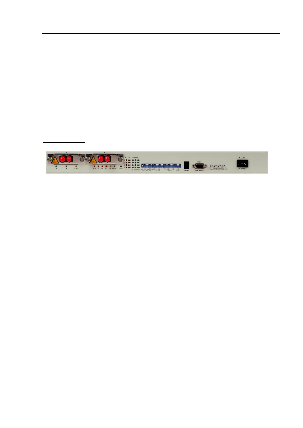
VI. Description about Functions
Front Panel:
§6.1 DIP Switches
There is a 28-bit DIP switch in the middle of the front panel. The default
configuration of the switches is: all dialed up (dialed up to OFF and down to
ON), and the functions of each bit are listed as below from left to right:
The first DIP switch:
The first bit (S/H): Selective switch of software control or panel hardware
(manual) control, all the setups are on the software control when the bit is
dialed down, and all the setups are on the panel hardware control when
dialed up.
The second bit (LA/RA): Selective switch of local/remote alarm indication.
With the hardware control enabled, dial up the bit to indicate local alarm,
down to indicate the remote alarm.
The third bit (LS): Selection for 2M loopback, Dial up to loop back the
local 2M interface, down to loop back the remote 2M interface.
The fourth bit (LL): Enable the loopback of the local optical interface. With
the hardware control enabled, dial the bit down to loop back the local
optical interface.
The fifth bit (ABEN): Enable the manual optical switching. With the
hardware control enabled, dial up the bit to use the default optical switching,
down to enable manual optical switching.

Modular Multi-service Integrated Optical Transmission Multiplexer User Manual
12
The sixth bit (A/B): Mandatorily dial it down to use the optical interface B,
dial it up to use the optical interface A. the bit is invalid in the case of
default optical switching.
The seventh bit (ETH): Configure the mandatory Ethernet functions. Dial
it up to auto-negotiating, down to mandatory; configure all the four Ethernet
interfaces to mandatory state of 100M, the full or half duplex is determined
by the state of the fourth DIP switch.
The eighth bit (PSEN): Enable switch of the downloading program. Dial
down to enable.
The second DIP switch (E1LOOP):
2M loopback operation, corresponding to 1-8 lines of 2M from left to right.
With the hardware control enabled, dial it down to enable the relevant 2M
loopback.
The third DIP switch (E1MASK):
2M mask operation, corresponding to 1-8 lines of 2M from left to right. With
the hardware control enabled, dial it down to enable the relevant 2M mask.
The fourth DIP switch (F/HDX):
The first bit: Mandatorily set the first line Ethernet interface as half duplex
mode, when the connected equipment of the first Ethernet interface is
working in half duplex mode, it is recommended to dial the bit down in
order to achieve better performance.
The second bit: Mandatorily set the second line Ethernet interface as half
duplex mode, when the connected equipment of the second Ethernet
interface is working in half duplex mode, it is recommended to dial the bit
down in order to achieve better performance.
The third bit: Mandatorily set the third line Ethernet interface as half
duplex mode, when the connected equipment of the third Ethernet
interface is working in half duplex mode, it is recommended to dial the bit
down in order to achieve better performance.
The fourth bit: Mandatorily set the fourth line Ethernet interface as half
duplex mode, when the connected equipment of the fourth Ethernet
interface is working in half duplex mode, it is recommended to dial the bit
down in order to achieve better performance.
Note: Every bit of the above-mentioned DIP switches shall be valid
only when the seventh bit (ETH) of the first DIP switch is dialed down.

User Manual Modular Multi-service Integrated Optical Transmission Multiplexer
13
§6.2 Pushbuttons
CALL: Order wire calling key
When calling the opposite terminal, push down the calling and the
opposite terminal will be ringing; when the local terminal is ringing, push
down the calling key to answer. Eject the key after finishing the call and put
it in hold.
MUTE: Configuration switch of Alarm sound.
With the button raised, an alarm will be emitted accompanied with
sound; Push it down, no matter whether there is an alarm signal, the
buzzer will not emit any sound. However, the switch will not impact the
buzzer warning for order wire phone.
RESET: Push it down and it will be raised automatically (unlocked), the
system will be reset. After new data downloaded, the data can be effective
only after resetting the switch. (Particular care shall be taken on the button
because the service will be interrupted when it is pushed down to reset the
system)
NMS/Hyper: Selection button of HyperTerminal network management
(DB9 interface) or 485/232 (RJ45 interface) network management. Raise it
to HyperTerminal network management (DB9 interface), when it does not
receive the network management data from RJ45 interface; Push it down
to 485/232 (RJ45 interface) network management, when it does not
receive the network management data from HyperTerminal network
management.
§6.3 Indication of Indicator Lamps
Functional indication:
Indicators
Description
PWR
Green, ON, referring to power supply in order;
A
Green, ON, referring to use optical interface A;
B
Green, ON, referring to use optical interface B;
MUTE
Yellow, ON, referring to mute state;
CALL
Yellow, ON, referring to an order wire call from the opposite terminal;

Modular Multi-service Integrated Optical Transmission Multiplexer User Manual
14
ALA
Red, always ON, referring to local alarm indication;
Red, Flashing, referring to remote alarm indication;
OPL
Red, ON, referring to optical loss alarm;
SYL
Red, ON, referring to the framing out-of-step of the optical signal;
E3
Red, ON, referring to system error code ≥10-3 alarm;
E6
Yellow, ON, referring to system error code≥10-6 alarm;
Ethernet interface:
Indicators
Description
Function description
Link
Twisted pair connection
and transmission
indicator
On: normal connection of
twisted pair
Off: no twisted pair connected
10/100
Indicator of working
speed
On: 100Mbps
Off: 10Mbps
F/HDX
Indicator for full/half
duplex
On: full duplex
Off: half duplex
(Note: ETH1, ETH2, ETH3, ETH4 are the four Ethernet interfaces)
E1 interface:
Indicators
Description
1
Red, ON, referring to code break alarm of the 1st line of E1;
2
Red, ON, referring to code break alarm of the 2nd line of E1;
3
Red, ON, referring to code break alarm of the 3rd line of E1;
4
Red, ON, referring to code break alarm of the 4th line of E1;
5
Red, ON, referring to code break alarm of the 5th line of E1;
6
Red, ON, referring to code break alarm of the 6th line of E1;
7
Red, ON, referring to code break alarm of the 7th line of E1;
8
Red, ON, referring to code break alarm of the 8th line of E1.
§6.4 Order Wire Interface (PHONE)
The equipment can provide one line of order wire telephone, to
facilitate the contact with the central management equipment room during
maintenance. Push it down to call the opposite terminal and keep it pushed
down during calling; Raise it to hang up or hold on.

User Manual Modular Multi-service Integrated Optical Transmission Multiplexer
15
The pin designation is as follows:
1: VOICE OUT 2: GND
3: VOICE IN 4: GND
§6.5 HyperTerminal Interface (DB9)
Connect the computer serial port with a parallel line of one male DB9
and one female BD9, select baud rate as 19200bps, no parity, data bit 8,
stop bit 1, data stream control NONE. Now the user can manage the
equipment of HyperTerminal.
§6.6 Optical Interface (dual optical interface, optical redundancy as
an optional function)
The “FIBER A” and “FIBER B” marked on the front panel refer to the
optical interface. Please select the plug mating with the type of optical
interface. Refer to the product information label at the outside of package
for the type of optical interface. IN (optical input) refers to the optical signal
input port,and OUT (optical output) refer to the optical signal output port. In
the case of single-fiber laser, signal receiving and transmitting is integrated
and the dual and single fibers can be used as one active and the other
standby. Carefully insert the optical jumper. The fiber connector shall not
be contaminated. Clean the fiber interface by lightly wiping with alcohol
4,3,2,1
Modular Multi-service Integrated Optical Transmission Multiplexer User Manual
16
before application, otherwise, it will bring negative impacts on transmission
quality. The inferior butt-connection of fiber connector may cause
significant power loss, so the optical connector shall be modified according
to the actual situation. Arrange the optic-fiber in the equipment room
rationally, with the fiber curvature radius no less than 50mm.
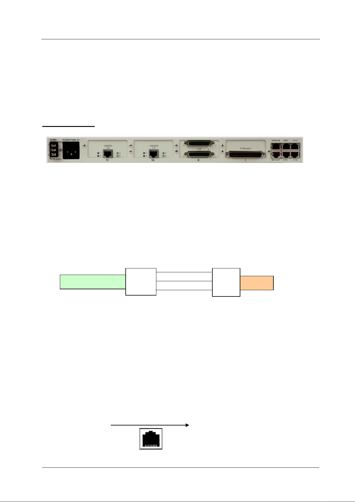
§6.7 Peripheral Interfaces
Rear Panel:
§6.7.1 Monitoring and Auxiliary Data Interfaces
1.DATA/ALM interface: asynchronous data transmitting port and
overhead alarm port
Asynchronous data transmitting port RS232: Definition: 1(TX),
2(RX), 3(GND); Unnecessary to configure, directly available for plug and
play, with the speed auto-negotiable.
Overhead alarm port ALM:
Definition: 7(ALM-A), 8(ALM-B)
When the alarm occurs again, ALM-A and ALM-B will be shorted.
2.NMS PORT: Network management monitoring interface of RS232
and RS422/485
Network management monitoring interface of RS232:
The pin designation is: 1(TX), 2(RX), 3(GND).
1,2,3,4,5,6,7,8
Pin arrangement of RJ45 socket
Optical Multiplexer
1
RJ45 2
3
2
3 DB9
5
PC

User Manual Modular Multi-service Integrated Optical Transmission Multiplexer
17
Monitoring interface of RS422/485: definition: 8(RX+), 7(RX-),
6(TX-), 5(TX+); Connect with the NM module with straight-through line.
Monitoring interface Selection of RS232 / (RS422/485):Use the
DIP switch under the soleplate of network management board to select
RS232 or RS485 interface as the network management interface. In the
case of RS232: 1,2,3,4,5 of DIP switch are dialed to ON, and other to OFF;
in the case of RS485/RS422: 6,7,8 of DIP switch are dialed to ON, and
1,2,3,4,5 to OFF.
3. Overhead alarm output
Alarm output port: Despite the above-mentioned overhead alarm
mode, the fourth bit pin of DATA/ALM port or NMS PORT is an alarm
output terminal, which can be led out if required. The alarm output mode
can be selected to be relay or electrical level mode. In the case of
electrical level, a 5V electrical level alarm signal will be exported; in the
case of relay, once there is an alarm, the relay will be connected, when the
overhead alarm signal is grounded so an alarm will be emitted.
§6.7.2 Ethernet interface
The equipment provides four 10/100Mbps fast Ethernet interfaces.
The UTP cable can adopt cables in class 3, 4 or 5, and the maximum
length of TP cable is 100m.
Note: When using Ethernet, it shall not be allowed that two
equipments are connected by two or more interfaces. When the
equipments at two ends have been connected via optic-fiber, it is not
allowed to add connections with the Ethernet.
Optical Multiplexer
1
RJ45 2
3
2
3 DB9
5
PC

Modular Multi-service Integrated Optical Transmission Multiplexer User Manual
18
Performance of Ethernet interface:
Accord with the standards IEEE802.3/u 10Base-T and
10/100Base-TX/FX
Supporting 802.3x full duplex flow control and Back Pressure half
duplex flow control
Chain alarm function of LinkLoss
Parallel or twisted pairs are mated by auto-negotiation.
§6.7.3 Bottom Board Preset Holes
There is a 4-digit patch switch inside the 4 small rectangular holes on
the bottom board of equipment.
I) When the plug-in interface board is G.703 (4×E1) interface board,
the switch is used as impedance match for E1 interface. The switch is set
up as per ordering instructions at the ex-work time. User can also make
field modification. (Attention: External adapter must be
corresponding!)
1 (The 1st E1)
2 (The 2nd E1)
3 (The 3rd E1)
4 (The 4th E1)
ON
OFF
ON
OFF
ON
OFF
ON
OFF
75Ω
120Ω
75Ω
120Ω
75Ω
120Ω
75Ω
120Ω
II) When the plug-in interface board is 2×V.35, the switch is used as
the clock setup for V.35 interface.
1
2
3
4
ON
ON
2 V.35 clocks in anti-phase
ON
ON
2 V.35 master reference
clocks
ON
OFF
The 1st V.35 clock in
anti-phase
ON
OFF
OFF
ON
2 V.35 external clocks
OFF
ON
The 2nd V.35 clock in
anti-phase
OFF
OFF
Neither of the two V.35
clocks in anti-phase
OFF
OFF
2 V.35 slave clocks
Table of contents
Popular Multiplexer manuals by other brands


PULSE+
PULSE+ O3-4D1L3 U2 manual

PerkinElmer
PerkinElmer M47-104 Maintenance manual

Black Box
Black Box MT14230A-SM-SC manual

Cronyx
Cronyx E1-XL/B-IP Installation and operating manual

American Dynamics
American Dynamics Multivision Quest TMV910Q Specifications

Patton electronics
Patton electronics 1195/4E1 Getting started guide


