DEUTSCHMANN AUTOMATION SPEEDY Series User manual

Instruction manual
Dynamic switching accelerator
SPEEDY
Deutschmann Automation GmbH & Co. KG
www.deutschmann.com | wiki.deutschmann.de

Handbuch Art.-Nr: V3140E

30.1.20 Instruction manual dynamical switching accelerator SPEEDY V. 3.1 3
Deutschmann Automation GmbH & Co. KG
Foreword
This operating manual provides users and OEM customers with all the information necessary for
the installation and operation of the product described in this manual.
All details contained in this manual have been checked carefully, however, they do not represent
an assurance of product characteristics. No liability can be accepted for errors. DEUTSCHMANN
AUTOMATION reserves the right to carry out alterations to the described products in order to
improve the reliability, function or design thereof. DEUTSCHMANN AUTOMATION only accepts
liability to the extent as described in the terms and conditions of sale and delivery.
All rights reserved, including translation. No part of this manual may be reproduced or proces-
sed, copied or distributed in any form whatsoever (print, copy, microfilm or any other process)
without written permission from DEUTSCHMANN AUTOMATION.
Bad Camberg, January 2020

Deutschmann Automation GmbH & Co. KG
4Instruction manual dynamical switching accelerator SPEEDY V. 3.1 30.1.20

30.1.20 Instruction manual dynamical switching accelerator SPEEDY V. 3.1 5
Deutschmann Automation GmbH & Co. KG
1 Introduction . . . . . . . . . . . . . . . . . . . . . . . . . . . . . 7
1.1 On this manual . . . . . . . . . . . . . . . . . . . . . . . . . . . . . . . 7
1.1.1 Symbols . . . . . . . . . . . . . . . . . . . . . . . . . . . . . . . . . . . . 7
1.1.2 Suggestions . . . . . . . . . . . . . . . . . . . . . . . . . . . . . . . . . . 7
2 EMC Directives for products of Deutschmann Automation . . . 8
3 Fields of application . . . . . . . . . . . . . . . . . . . . . . . . 9
4 Installation, connection and display . . . . . . . . . . . . . . . 10
4.1 Dimensions and mounting . . . . . . . . . . . . . . . . . . . . . . . . 10
4.2 Terminal assignment . . . . . . . . . . . . . . . . . . . . . . . . . . . 10
4.2.1 Option X79 - 42V holding level . . . . . . . . . . . . . . . . . . . . . . . .10
4.3 LEDs . . . . . . . . . . . . . . . . . . . . . . . . . . . . . . . . . . . 11
5 SPEEDY switching modes . . . . . . . . . . . . . . . . . . . . 12
5.1 Setting the switching modes . . . . . . . . . . . . . . . . . . . . . . . 12
5.2 Switching mode 1 . . . . . . . . . . . . . . . . . . . . . . . . . . . . . 13
5.3 Switching mode 2 . . . . . . . . . . . . . . . . . . . . . . . . . . . . . 14
5.4 Switching mode 3 . . . . . . . . . . . . . . . . . . . . . . . . . . . . . 15
5.5 Switching mode 4 . . . . . . . . . . . . . . . . . . . . . . . . . . . . . 16
5.6 Switching mode 5 . . . . . . . . . . . . . . . . . . . . . . . . . . . . . 17
6 Commissioning and optimisation of the switching time . . . . 18
6.1 Recovery times of SPEEDY . . . . . . . . . . . . . . . . . . . . . . . . 18
7 Technical data . . . . . . . . . . . . . . . . . . . . . . . . . . . 19
7.1 SPEEDY-100V . . . . . . . . . . . . . . . . . . . . . . . . . . . . . . 19
7.2 SPEEDY-50V . . . . . . . . . . . . . . . . . . . . . . . . . . . . . . . 19
8 Servicing . . . . . . . . . . . . . . . . . . . . . . . . . . . . . . 20
8.1 Returning a unit . . . . . . . . . . . . . . . . . . . . . . . . . . . . . . 20
8.2 Internet . . . . . . . . . . . . . . . . . . . . . . . . . . . . . . . . . . 20

Deutschmann Automation GmbH & Co. KG
6Instruction manual dynamical switching accelerator SPEEDY V. 3.1 30.1.20

30.1.20 Instruction manual dynamic switching accelerator SPEEDY V. 3.1 7
Deutschmann Automation GmbH & Co. KG Introduction
1 Introduction
1.1 On this manual
This manual documents installation, functions and operation of the Deutschmann unit specified
on the cover sheet and in the header.
1.1.1 Symbols
Particularly important text sections can be seen from the adjacent picto-
gram.
You should always follow this information since, otherwise, this could result in
malfunctions or operating errors.
1.1.2 Suggestions
We are always pleased to receive suggestions and wishes etc. and endeavour to allow for these.
It is also helpful if you bring our attention to any errors.

EMC Directives for products of Deutschmann Automation Deutschmann Automation GmbH & Co. KG
8Instruction manual dynamic switching accelerator SPEEDY V. 3.1 30.1.20
2 EMC Directives for products of Deutschmann Automation
The installation of our products has to be carried out considering the relevant EMC directives as
well as our internal instructions.
For more information see ’EMC Directives’ on our homepage at http://www.deutschmann.de.

30.1.20 Instruction manual dynamic switching accelerator SPEEDY V. 3.1 9
Deutschmann Automation GmbH & Co. KG Fields of application
3 Fields of application
When switching on and also switching off magnetic controlled connecting devices delays appear
that consist of two components:
•delay period for building up or reducing the magnetic field
•delay period time lag to overcome the mechanical inertia
To shorten the delay period SPEEDY offers the possibility to achieve an overexcitation of the
magnetic field by an over-voltage impulse of 100V, adjustable from 1ms to 10ms. Therefore the
mechanical inertia can be overcome faster.
When switching off the delay period for the reduction of the magnetic field is considerably
decreased by a negative free wheeling voltage.
The status of the inputs and outputs, also of the supply voltages, is optionally displayed by inte-
grated LEDs.
SPEEDY has different switching modes, which are externally adjustable. They are described in
detail in the following chapters.

Installation, connection and display Deutschmann Automation GmbH & Co. KG
10 Instruction manual dynamic switching accelerator SPEEDY V. 3.1 30.1.20
4 Installation, connection and display
4.1 Dimensions and mounting
SPEEDY is supplied in a plastic housing for snap-mounting onto a commercially available EN
mounting rail.
The dimensions are shown in the drawing below:
Picture 1: Dimensional drawing SPEEDY
4.2 Terminal assignment
SPEEDY is connected via a 10-pin screw-plug connector. The following terminal assignment
applies:
Terminal Function
1 GND (reference for terminal 3-6)
2 GND (reference for terminal 3-6)
3 Input 4 (24V/max. 10mA)
4 Input 3 (24V/max. 10mA)
5 Input 2 (24V/max. 10mA)
6 Input 1 (24V/max. 10mA)
7 Output 2 (max. 1A)
8 Output 1 (max. 1A)
9 GND (reference for terminal 7, 8 and 10)
10 10... 30V (max. 3A)
4.2.1 Option X79 - 42V holding level
For devices with this option the holding level of 42V is supplied through PIN1. In other respects
the device acts as a standard device SPEEDY.

30.1.20 Instruction manual dynamic switching accelerator SPEEDY V. 3.1 11
Deutschmann Automation GmbH & Co. KG Installation, connection and display
The following assignment applies:
Terminal Function
1 Input holding level 42V (max. 50V)
2 GND (reference for terminal 3-6)
3 Input 4 (24V/max. 10mA)
4 Input 3 (24V/max. 10mA)
5 Input 2 (24V/max. 10mA)
6 Input 1 (24V/max. 10mA)
7 Output 2 (max. 1A)
8 Output 1 (max. 1A)
9 GND (reference for terminal 7, 8 and 10)
10 10... 30V (max. 3A)
4.3 LEDs
SPEEDY has 8 LEDs with the following meaning:
LED over terminal Color Meaning
3 Red Input 4
4 Red Input 3
5 Red Input 2
6 Red Input 1
7 Green Output 2
8 Green Output 1
9 Green Internal voltage supply ok
10 Green External voltage supply ok

SPEEDY switching modes Deutschmann Automation GmbH & Co. KG
12 Instruction manual dynamic switching accelerator SPEEDY V. 3.1 30.1.20
5 SPEEDY switching modes
5.1 Setting the switching modes
The switching modes described below are selected via a rotary coding switch.
The following assignment applies:
Rotary-switch indication Switching mode Input interference suppression
0 1 Switched off
1 2 Switched off
2 3 Switched off
3 4 Switched off
4 5 (1ms) Switched off
5 5 (2ms) Switched off
6 5 (5ms) Switched off
7 5 (10ms) Switched off
8 1 Active
9 2 Active
A 3 Active
B 4 Active
C 5 (1ms) Active
D 5 (2ms) Active
E 5 (5ms) Active
F 5 (10ms) Active
Please note that every change of the inputs is evaluated directly in the first 8 switch positions.
This mode is practical if the inputs are connected to the outputs of a control and SPEEDY is
required to provide an immediate response.
If interference suppression is activated, the input signals are filtered which leads to a delay (prop-
agation time input --> output) of approx. 1 ms.
This operating mode is practical if the inputs are switched by a relay or if the input lines are sub-
ject to very strong interference.

30.1.20 Instruction manual dynamic switching accelerator SPEEDY V. 3.1 13
Deutschmann Automation GmbH & Co. KG SPEEDY switching modes
5.2 Switching mode 1
In switching mode 1, input 1 is switched to output 1 and input 2 is switched to output 2. The dura-
tion of the overexcitation pulse is set at the inputs 3 and 4.
Picture 2: Switching mode 1
Input 3 Input 4 Pulse
0 VDC 0 VDC 1 ms
+24 VDC 0 VDC 2 ms
0 VDC +24 VDC 5 ms
+24 VDC +24 VDC 10 ms
SPEEDY switching modes Deutschmann Automation GmbH & Co. KG
14 Instruction manual dynamic switching accelerator SPEEDY V. 3.1 30.1.20
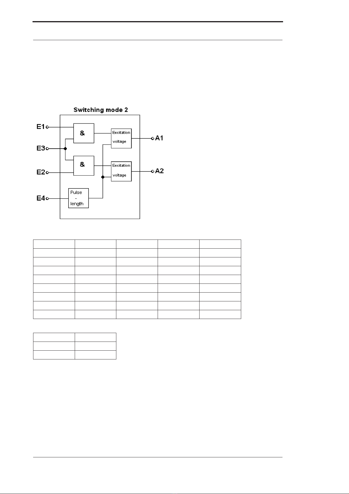
5.3 Switching mode 2
In switching mode 2, input 1 is switched to output 1 and input 2 is switched to output 2. Input 3 is
an Enable input. If there is no signal at input 3, input 1 and input 2 are inoperable. The duration of
the overexcitation pulses is set at input 4.
Picture 3: Switching mode 2
Input 1 Input 2 Input 3 Output 1 Output 2
0 VDC 0 VDC 0 VDC 0 VDC 0 VDC
+24 VDC 0 VDC 0 VDC 0 VDC 0 VDC
0 VDC +24 VDC 0 VDC 0 VDC 0 VDC
+24 VDC +24 VDC 0 VDC 0 VDC 0 VDC
0 VDC 0 VDC +24 VDC 0 VDC 0 VDC
+24 VDC 0 VDC +24 VDC +UB 0 VDC
0 VDC +24 VDC +24 VDC 0V +UB
+24 VDC +24 VDC +24 VDC +UB +UB
Input 4 Pulse
0 VDC 2 ms
+24 VDC 5 ms

30.1.20 Instruction manual dynamic switching accelerator SPEEDY V. 3.1 15
Deutschmann Automation GmbH & Co. KG SPEEDY switching modes
5.4 Switching mode 3
Switching mode 3 was developed specifically for twin solenoids (actuating elements). If input 1
has no signal, output 2 is switched. If input 1 receives a signal, output 2 is deactivated first. After
deactivation, there is a pause **. Output 1 is then activated.
The situation is different if the signal at input 1 is cancelled. Output 1 is deactivated first, followed
by a pause **, after which (not before) output 2 is switched back on. Input 2 determines the dura-
tion of the pause **. The duration of the overexcitation pulse is set at inputs 3 and 4.
Picture 4: Switching mode 3
Input 1 Output 1 Output 2
0 VDC 0 VDC +UB
+24 VDC +UB 0 VDC
Input 3 Input 4 Pulse
0 VDC 0 VDC 1 ms
+24 VDC 0 VDC 2 ms
0 VDC +24 VDC 5 ms
+24 VDC +24 VDC 10 ms
Input 2 Pause **
0 VDC Pulse x 2
+24 VDC Pulse x 1
** Pause: Period between de-energisation of solenoid 1 and energisation of solenoid 2 or vice
versa. It results from the overexcitation time (pulse) multiplied by 2 or 1.

SPEEDY switching modes Deutschmann Automation GmbH & Co. KG
16 Instruction manual dynamic switching accelerator SPEEDY V. 3.1 30.1.20
5.5 Switching mode 4
Switching mode 4 includes an RS flip-flop logic (RESET/SET logic). If 24 V is applied to input 2
(RESET) after power-up, output 2 is switched. If 24 V is also applied to input 1 (SET), output 1 is
switched and output 2 is deactivated. When the signal input 1 (SET) is cancelled again, this state
remains stable at the outputs. If the signal is now cancelled at input 2 (RESET) (0 V DC), output
1 is deactivated and output 2 is activated. This circuit state remains stable even if input 2
receives a signal again (+24 V DC). Input 2 (RESET) has priority over input 1 (SET), i. e. if input
1 has a signal (+24 V DC) and input 2 has no signal (0 V DC), output 2 is switched and output 1
is deactivated. The duration of the overexcitation pulse is set at inputs 3 and 4 (terminals 3 and
4).
Picture 5: Switching mode 4
Input 1 Input 2 Output 1 Output 2
0 VDC 0 VDC 0 VDC +UB
+24 VDC 0 VDC 0 VDC +UB
0 VDC +24 VDC Unchanged Unchanged
+24 VDC +24 VDC +UB 0 VDC
Input 3 Input 4 Pulse
0 VDC 0 VDC 1 ms
+24 VDC 0 VDC 2 ms
0 VDC +24 VDC 5 ms
+24 VDC +24 VDC 10 ms

30.1.20 Instruction manual dynamic switching accelerator SPEEDY V. 3.1 17
Deutschmann Automation GmbH & Co. KG SPEEDY switching modes
5.6 Switching mode 5
Switching mode 5 also includes an RS flip-flop which is set via inputs 1 and 2 and reset via inputs
3 and 4 (cf. description in switching mode 4). The pulse length is set via the rotary coding switch,
with the following assignment:
Picture 6: Switching mode 5
Rotary switch indication Pulse
4 or C (see chapter 5.1) 1ms
5 or D (see chapter 5.1) 2ms
6 or E (see chapter 5.1) 5ms
7 or F (see chapter 5.1) 10ms
Input 1 Input 2 Input 3 Input 4 Output 1 Output 2
0 VDC 0 VDC 0 VDC 0 VDC Unchanged Unchanged
+24 VDC 0 VDC 0 VDC 0 VDC Unchanged Unchanged
0 VDC +24 VDC 0 VDC 0 VDC Unchanged Unchanged
+24 VDC +24 VDC 0 VDC 0 VDC +UB 0 VDC
0 VDC 0 VDC +24 VDC 0 VDC 0 VDC +UB
+24 VDC 0 VDC +24 VDC 0 VDC 0 VDC +UB
0 VDC +24 VDC +24 VDC 0 VDC 0 VDC +UB
+24 VDC +24 VDC +24 VDC 0 VDC 0 VDC +UB
0 VDC 0 VDC 0 VDC +24 VDC Unchanged Unchanged
+24 VDC 0 VDC 0 VDC +24 VDC Unchanged Unchanged
0 VDC +24 VDC 0 VDC +24 VDC Unchanged Unchanged
+24 VDC +24 VDC 0 VDC +24 VDC +UB 0 VDC
0 VDC 0 VDC +24 VDC +24 VDC Unchanged Unchanged
+24 VDC 0 VDC +24 VDC +24 VDC Unchanged Unchanged
0 VDC +24 VDC +24 VDC +24 VDC Unchanged Unchanged
+24 VDC +24 VDC +24 VDC +24 VDC +UB 0 VDC

Commissioning and optimisation of the switching time Deutschmann Automation GmbH & Co. KG
18 Instruction manual dynamic switching accelerator SPEEDY V. 3.1 30.1.20
6 Commissioning and optimisation of the switching time
First, the inputs, outputs and the supply voltage for SPEEDY must be wired. When doing this,
please note that the inputs feature optocouplers and a separate GND input.
Then set the required switching mode with the rotary coding switch. If optimisation has not yet
been carried out, the overexcitation time should be set to the minimum value (1 ms).
When all preparations are complete, you can connect the supply voltage to SPEEDY.
For optimisation, the time of the overvoltage pulse can now be incremented step by step until no
further improvement of the switching time is reached.
ATTENTION:
Increasing the pulse time further does not have any positive effect and
simply unnecessarily loads the switching elements.
Note:
The switch-off delay can be reduced without affecting the switch-on delay by reducing the hol-
ding voltage (e. g. 12V instead of 24V).
6.1 Recovery times of SPEEDY
The overexcitation voltage of 100 V is generated internally by SPEEDY and buffered in a capac-
itor. The capacitor is partially discharged when a pulse is issued and a "recovery time" is required
until the capacitor has fully recharged. This recovery time is specified in the table below:
Current (mA) 1ms-pulse 2ms-pulse 5ms-pulse 10ms-pulse
0 0 ms 0 ms 0 ms 0 ms
100 1 ms 2 ms 6 ms 13 ms
200 2 ms 4 ms 12 ms 26 ms
300 2 ms 5 ms 17 ms 39 ms
400 3 ms 7 ms 23 ms 52 ms
500 3 ms 9 ms 29 ms 65 ms
600 4 ms 11 ms 35 ms 78 ms
700 4 ms 12 ms 41 ms 91 ms
800 5 ms 14 ms 47 ms 104 ms
900 5 ms 15 ms 52 ms 117 ms
1000 6 ms 17 ms 58 ms 130 ms
1500 28 ms 60 ms 117 ms 170 ms
2000 34 ms 70 ms 130 ms 180 ms
3000 50 ms 94 ms 160 ms 200 ms
Please note that the recovery time always applies to both outputs, i. e. if both outputs are
switched simultaneously, the total of the two output currents must be allowed for as the current in
the table.
If both outputs are switched time-delayed, only the time between the switch-off edge of the first
output’s over-current impulse and the switch-on edge of the next output has to be taken into con-
sideration as the recovery time.

30.1.20 Instruction manual dynamic switching accelerator SPEEDY V. 3.1 19
Deutschmann Automation GmbH & Co. KG Technical data
7 Technical data
7.1
SPEEDY-100V-1A SPEEDY-100V-4A
Operating voltage 10... 30V, max 1 W (unloaded) 10... 30V, max 1 W (unloaded)
Current consumption Max. 40mA (idle state)
max. 3A (at switching instant)
Max. 40mA (idle state)
max. 3A (at switching instant)
Inputs 4
Ri > 3.9 k
UL= OV - 3V, UH= 12V - 30V
4
Ri > 3.9 k
UL= OV - 3V, UH= 12V - 3V
Outputs 2
Iout < 1A steady load
Uout-Stat > operating voltage - 1V
Uout-pulse = 88V .. 100V
2
Iout 4A steady load / temporarily 5A (max. 1min.)
Uout-Stat > operating voltage - 1V
Uout-pulse = 88V .. 100V
Programs Can be set via 5 rotary switches
other customized programs on request
Can be set via 5 rotary switches
other customized programs on request
Pulse length Can be set 1 - 10ms Can be set 1 - 10ms
Switching delay < 300 μs (without input interference
suppression)
< 300 μs (without input interference suppression)
Recovery time Max. 150ms at 1A load and 10ms pulse Max. 200ms at 3A load and 10ms pulse
Housing Plastic for EN mounting rail mounting
(can be lined up)
W x H x D: 25 x 79 x 90.5mm
Plastic for EN mounting rail mounting (can be
lined up)
W x H x D: 25 x 79 x 90.5mm
Conductor connection Via plug terminal block up to 2.5mm2Via plug terminal block up to 2.5mm2
Display Optional LED status display of the
inputs, outputs and supply voltages
Optional LED status display of the inputs, outputs
and supply voltages
SPEEDY-100V
7.2 SPEEDY-50V
SPEEDY-50V-1A SPEEDY-50V-4A
Operating voltage 10... 30V, max 1 W (unloaded) 10... 30V, max 1 W (unloaded)
Current consumption Max. 40mA (idle state)
max. 3A (at switching instant)
Max. 40mA (idle state)
max. 3A (at switching instant)
Inputs 4
Ri > 3.9 k
UL= OV - 3V, UH= 12V - 30V
4
Ri > 3.9 k
UL= OV - 3V, UH= 12V - 3V
Outputs 2
Iout < 1A steady load
Uout-Stat > operating voltage - 1V
Uout-pulse = 44V .. 50V
2
Iout 4A steady load / temporarily 5A (max. 1min.)
Uout-Stat > operating voltage - 1V
Uout-pulse = 44V .. 50V
Programs Can be set via 5 rotary switches
other customized programs on request
Can be set via 5 rotary switches
other customized programs on request
Pulse length Can be set 1 - 10ms Can be set 1 - 10ms
Switching delay < 300 μs (without input interference
suppression)
< 300 μs (without input interference suppression)
Recovery time Max. 150ms at 1A load and 10ms pulse Max. 200ms at 3A load and 10ms pulse
Housing Plastic for EN mounting rail mounting
(can be lined up)
W x H x D: 25 x 79 x 90.5mm
Plastic for EN mounting rail mounting (can be
lined up)
W x H x D: 25 x 79 x 90.5mm
Conductor connection Via plug terminal block up to 2.5mm2Via plug terminal block up to 2.5mm2
Display Optional LED status display of the
inputs, outputs and supply voltages
Optional LED status display of the inputs, outputs
and supply voltages

Servicing Deutschmann Automation GmbH & Co. KG
20 Instruction manual dynamic switching accelerator SPEEDY V. 3.1 30.1.20
8 Servicing
Should questions arise that are not covered in this manual you can find further information in our
•FAQ/Wiki area on our homepage www.deutschmann.com or directly in our Wiki on
www.wiki.deutschmann.de
•Corresponding Manual of the used Cam Control
If your questions are still unanswered please contact the responsible sales partner (see
www.deutschmann.com) or contact us directly.
Please note down the following information before calling:
•Device designation
•Serial number (S/N)
•Article number
•Error number and error description
Your request will be recorded in the Support center and will be processed by our Support Team
as quickly as possible (Usually in 1 working day, rarely more than 3 working days.).
Technical Support hours are as follows:
Monday to Thursday from 8 am to midday and from 1 pm to 4 pm, Friday from 8 am to midday
(CET).
Deutschmann Automation GmbH & Co. KG
Carl-Zeiss-Straße 8
D-65520 Bad-Camberg
Germany
Central office and sales department +49 6434 9433-0
Technical Support +49 6434 9433-33
Fax sales department +49 6434 9433-40
Fax Technical Support +49 6434 9433-44
8.1 Returning a unit
If you return a unit to us, we require as comprehensive a description of the error as possible. We
require the following information in particular:
•What error number was displayed?
•How is the unit externally wired (encoders, outputs, ..)? Please state all connections of the unit.
•What is the magnitude of the 24V supply voltage (± 0.5V) with connected SPEEDY?
•What were you last doing on the unit (programming, error on power-up, ...)?
The more precise your information and error description, the more precisely we can check the
possible causes.
This manual suits for next models
4
Table of contents
Popular Switch manuals by other brands

Nortel
Nortel movianVPN quick reference

HITROL
HITROL HTM-20N Series instruction manual

aci
aci A/MCS Installation and operation instructions

HPP Enterprises
HPP Enterprises FlexNetwork 7500 Series Configuration guide

Kramer
Kramer ASPEN-1616UX quick start guide

Allied Telesis
Allied Telesis AT-9424Ts/XP AC datasheet


