ABB EOHU Series Training manual

EOHU364/5/6JK/RK/S/SS
NEMA 12, 3R, 4X / 200 A, 400 A, 600 A
Instruction Bulletin / Boletín de instrucciones / Directives d‘utilisation / 34EOHU364-5-6JRS / A, 1SCC340038M1401

Retain for future use. / Conservar para uso futuro. / À conserver pour usage ultérieur.

EOHU364/5/6JK/RK/S/SS
NEMA 12, 3R, 4X / 200 A, 400 A, 600 A
2
1
3
EOHU Series
Heavy Duty Non-fusible Safety Switches
EOHU Serie
Interruptores de seguridad de servicio pesado
EOHU Série
Interrupteurs de sécurité pour service intensif
200 A, 400 A, 600 A
NEMA 12: EOHU364JK, EOHU365JK, EOHU366JK
NEMA 3R: EOHU364RK, EOHU365RK, EOHU366RK
NEMA 4X: EOHU364S, EOHU364SS, EOHU365S, EOHU365SS,
EOHU366S, EOHU366SS
Instruction Bulletin / Boletín de instrucciones / Directives d‘utilisation, 1SCC340038M1401 / A | EOHU364/5/6JK/RK/S/SS 3
French version is available at later date.

1

1
EOHU Series
Heavy Duty Non-fusible Safety Switches
General safety instructions 1/2
Receiving, handling and storage 1/3
Applications 1/4
Product overview 1/5
EOHU364JK/_RK/_S/_SS, EOHU365JK/_RK/_S/_SS,
EOHU366JK/_RK/_S/_SS 1/5
Ratings 1/6
Heavy duty non-fusible safety switches 1/6
Cabling 1/7
Heavy duty non-fusible safety switches 1/7
Neutral bus and auxiliary contacts 1/8
Installation 1/9
Opening the enclosure 1/9
Knockouts 1/10
Mounting 1/11
Wiring 1/12
Neutral assembly (optional) 1/13
Auxiliary contact (optional) 1/14
Operation 1/15
Operating 1/15
Operating mechanism 1/16
Padlocking handle and door latches 1/18
Dimension drawings 1/19
EOHU364JK/_RK/_S/_SS, EOHU365JK/_RK/_S/_SS, EOHU366JK/_RK/_S/_
SS / NEMA 12, 3R, 4X / 200 A, 400 A, 600 A 1/19
Cable outlets / knockouts for NEMA 12 and 3R types 1/20
Accessories (optional) 1/21
Ordering information 1/21
Maintenance 1/22
Replacement parts, ordering information 1/22
Installation and maintenance log 1/23
Instruction Bulletin EOHU364/5/6JK/RK/S/SS, 1SCC340038M1401 / A | EOHU Series 1/1

1
1/2 General safety instructions | Instruction Bulletin EOHU364/5/6JK/RK/S/SS, 1SCC340038M1401 / A
General safety instructions
HAZARD OF ELECTRIC SHOCK, EXPLOSION, OR ARC FLASH
– Apply appropriate personal protective equipment (PPE) and
follow safe electrical work practices. See NFPA 70E or CSA
Z462.
– This equipment must only be installed and serviced by
qualified electrical personnel.
– Before performing visual inspections, tests, or maintenance
on the equipment, disconnect all sources of electric power.
Assume that all circuits are live unless they are completely
deenergized, tested, grounded, and tagged. Pay particular
attention to the design of the power system. Consider all
sources of power, including the possibility of backfeeding.
– Never operate energized switch with door open.
– Turn off switch before making load side connections.
– Always use a properly rated voltage sensing device at all line
to confirm switch is off.
– Turn off power supplying switch before doing any other work
on or inside switch.
Failure to follow these instructions will result in death or
serious injury.
Read these safety instructions carefully before using this product!
DANGER

1
Instruction Bulletin EOHU364/5/6JK/RK/S/SS, 1SCC340038M1401 / A | Receiving, handling and storage 1/3
Receiving, handling and storage
Receiving and handling
Upon receipt, carefully inspect the switch for damage that may
have occurred during transit. If damage is evident, or there is
visible indication of rough handling, immediately file a damage
claim with the transportation company, and notify your local
ABB sales office.
Do not remove the shipping package until ready to install the
switch.
WARNING
HAZARD OF EQUIPMENT OVERTURNING
When moving with a fork lift, do not remove the shipping package until
the device is in its final location.
Failure to follow this instruction will result in personal injury or
equipment damage.
Storage
If the unit will not be placed into service immediately, store
the switch on its original package in a clean, dry location. To
prevent condensation, maintain a uniform temperature. Store
the unit in a heated building, allowing adequate air circulation
and protection from dirt and moisture. Storing the unit outdoors
could cause harmful condensation inside the switch enclosure.

1
1/4 Applications | Instruction Bulletin EOHU364/5/6JK/RK/S/SS, 1SCC340038M1401 / A
Applications
Heavy duty non-fusible safety switches offer the ability to
manually open and close a circuit. Products can be used as
disconnecting means or on the load side of a branch circuit
protective device and are suitable for use as motor disconnects.
General purpose current ratings: 200 A, 400 A and 600 A
Standards: UL98, UL50, NEMA KS1, CSA
Catalog numbers:
TYPE 12: EOHU364JK, EOHU365JK, EOHU366JK
TYPE 3R: EOHU364RK, EOHU365RK, EOHU366RK
Enclosure material specification: Electrically galvanized steel,
polyester powder coating. Thickness: door and enclosure 0.059
in /1.5 mm (EOH364K/5K) and 0.079 in /2 mm (EOH366K).
Handle: glass reinforced polyamide (PA f1), polycarbonate (PC f1).
Enclosure color: ANSI 61 (light gray).
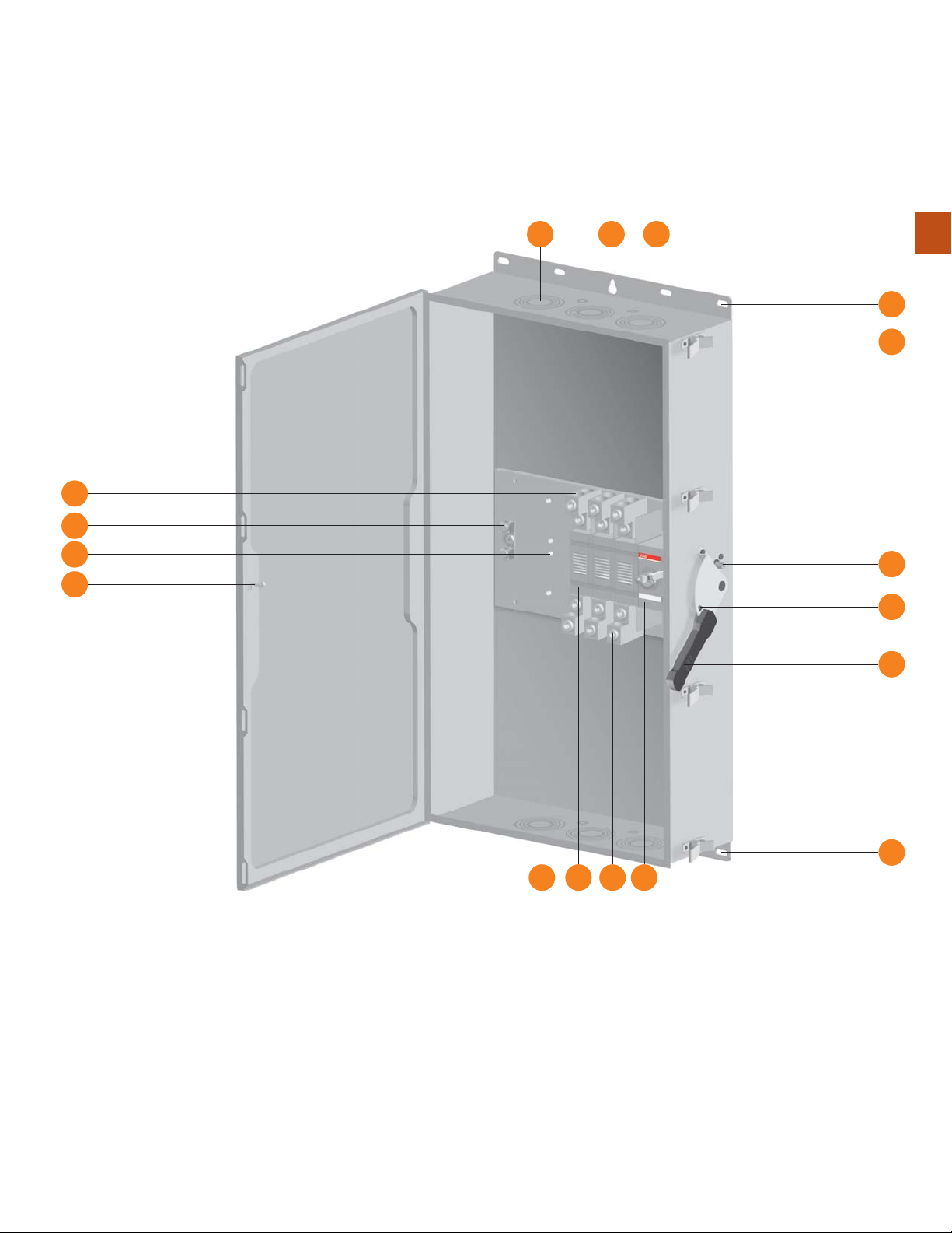
The EOHU series non-fusible safety switches are side-operated,
3 pole, 600V, available in UL environmental ratings TYPE 12 and
TYPE 3R housed in steel sheet enclosures and TYPE 4X housed
in stainless steel sheet enclosures.
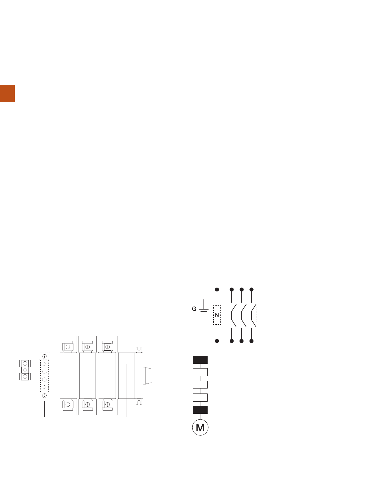
The EOHU364JK/_RK/_S/_SS, EOHU365JK/_RK/_S/_SS, EOHU366JK/_RK/_S/_SS non-fusible safety switches up to 600 VAC, 3-ph with the ground bus
(included) and the neutral link N (optional)
Catalog numbers:
TYPE 4X: EOHU364S, EOHU365S, EOHU366S
Enclosure material specification: Stainless steel sheet, Grade
304: AISI304. Thickness: door and enclosure 0.059 in /1.5 mm
(EOH364K/5K) and 0.079 in /2 mm (EOH366K). Handle: glass
reinforced polyamide (PA f1), polycarbonate (PC f1).
Catalog numbers:
TYPE 4X: EOHU364SS, EOHU365SS, EOHU366SS
Enclosure material specification: Stainless steel sheet, Grade
316: AISI316. Thickness: door and enclosure 0.059 in /1.5 mm
(EOH364K/5K) and 0.079 in /2 mm (EOH366K). Handle: glass
reinforced polyamide (PA f1), polycarbonate (PC f1).
Controller
Disconnecting means
Short circuit protective device
Overload protection
Motor disconnection
Auxiliary contacts
(optional) inside the
mechanism
Ground
bus
Neutral link
(optional)

1
3 4
3 8
2
14
13
7
9
12
15
610
11
5
5
1
Instruction Bulletin EOHU364/5/6JK/RK/S/SS, 1SCC340038M1401 / A | Product overview 1/5
Product overview
EOHU364JK/_RK/_S/_SS, EOHU365JK/_RK/_S/_SS,
EOHU366JK/_RK/_S/_SS
1. Door latches, provision for padlocking
2. Handle
3. Knockouts in catalog numbers EOHU364JK/_RK, EOHU365JK/_RK and
EOHU366JK/_RK (TYPE12 and 3R), blank in catalog numbers
EOHU364S/_SS, EOHU365S/_SS and EOHU366S/_SS (TYPE 4X)
4. Keyslot mounting hole (1 pc / side)
5. Mounting holes (EOHU364JK/_RK/_S/_SS: 2 pcs / side,
EOHU365/6JK/_RK/_S/_SS: 4 pcs / side)
6. 3-pole switch, double breaking contacts with viewing windows
7. Line side terminal lugs
8. Load side terminal lugs
9. Ground bus (2 lugs)
10. Operating mechanism, inside place for auxiliary contacts (optional)
11. Door interlock mechanism
12. Locking hook for door interlock mechanism
13. Door interlock bypass shaft (Only qualified personnel should perform this
procedure)
14. Hole for padlocking the handle (3 padlocks)
15. Place for neutral assembly (optional)

1
1/6 Ratings | Instruction Bulletin EOHU364/5/6JK/RK/S/SS, 1SCC340038M1401 / A
Non-fusible safety switch catalog number EOHU364_ EOHU365_ EOHU366_
AMPS A 200 400 600
General purpose current rating A 200 400 600
Max. horse power rating Three phase 240 V HP 60 125 200
480 V HP 125 250 400
600 V HP 150 350 500
Max. motor FLA current Three phase 240 V A 192 360 480
480 V A 156 302 477
600 V A 144 336 472
Short circuit rating Class R, J or T fuses 480 V kA 200 200 200
Class R fuses 600 V kA 200 100 200
Class J or T fuses 600 V kA 200 200 200
Ground bus
Ground bus catalog number OZXG1 OZXG2 OZXG2
Temperature rating °F 167 167 167
°C 75 75 75
Auxiliary contacts, optional
Suitable auxiliary contacts Function 1NO OA1G10 OA1G10 OA1G10
1NC OA3G01 OA3G01 OA3G01
Nema ratings, AC AC600 AC600 AC600
AC rated voltage VAC 600 600 600
AC rated thermal current A 10 10 10
AC maximum volt-ampere making VA 7200 7200 7200
AC maximum volt-amperage breaking VA 720 720 720
Nema ratings, DC R300 R300 R300
DC rated voltage VDC 300 300 300
DC rated thermal current A 1 1 1
DC maximum make-break VA 28 28 28
Ratings
Heavy duty non-fusible safety switches

1
Instruction Bulletin EOHU364/5/6JK/RK/S/SS, 1SCC340038M1401 / A | Cabling 1/7
Cabling
Heavy duty non-fusible safety switches
Cabling / Non-fusible safety switches
Cable entry/exit locations: Top entry-bottom exit.
Cable entry/exit through top/bottom endwalls maximize the
cable bending area. All cable entry/exit must be in accordance
with the National Electrical Code and all other local codes. Use
3/8 (for 200 A) or 1/2 (for 400 A and 600 A) Hex key / wrench.
See chapter Wiring.
WARNING
To avoid hazard of electric shock, turn off and lock out all power
sources before installing or performing maintenance on this equipment.
Non-fusible safety switch catalog number EOHU364_ EOHU365_ EOHU366_
AMPS 200 400 600
Line side terminal lugs
Terminal lug OZXA-400 OZXA-800 OZXA-800
Torque: wire tightening for Cu and Al cables lbs.in 375 500 500
Nm 41.8 55.7 55.7
Lug mounting torque lbs.in 228 480 480
Nm 25.4 53.5 53.5
Wire range kcmil #2 - 600 (2) #2 - 600 (2) #2 - 600
mm235 - 300 2 × 35 - 300 2 × 35 - 300
Load side terminal lugs
Terminal lug OZXA-400 OZXA-800 OZXA-800
Torque: wire tightening for Cu and Al cables lbs.in 375 500 500
Nm 41.8 55.7 55.7
Lug mounting torque lbs.in 228 480 480
Nm 25.4 53.5 53.5
Wire range kcmil #2 - 600 (2) #2 - 600 (2) #2 - 600
mm235 - 300 2 × 35 - 300 2 × 35 - 300
Ground bus (2 lugs)
Screwdriver Slot 5/16” Hex 5/16” Hex
Ground bus catalog number OZXG1 OZXG2 OZXG2
Torque: wire tightening for Cu and Al cables lbs.in 50 275 275
Nm 5.6 31.1 31.1
Maximum stud mounting torque lbs.in 72 72 72
Nm 8.1 8.1 8.1
Wire range AWG #14 - 2 #6 - 250 kcmil #6 - 250 kcmil
mm22.5 - 35 10 - 120 10 - 120

1
1/8 Cabling | Instruction Bulletin EOHU364/5/6JK/RK/S/SS, 1SCC340038M1401 / A
Cabling
Neutral bus and auxiliary contacts
Cabling / Neutral bus (optional)
Use 5/32 hex key/wrench. See chapter Installation / Neutral assembly (optional).
Non-fusible safety switch catalog number EOHU364_ EOHU365_ EOHU366_
AMPS A 200 400 600
Suitable neutral bus, catalog number EOHXSN4 EOHXSN56 EOHXSN56
Neutral bus / terminal lugs
Terminal lug OZXA-400 OZXA-800 OZXA-800
Torque: wire tightening Copper lbs.in 375 500 500
Nm 41.8 55.7 55.7
Torque: wire tightening Aluminum lbs.in 375 500 500
Nm 41.8 55.7 55.7
Lug mounting torque lbs.in 228 480 480
Nm 25.4 53.5 53.5
Wire range kcmil #2 - 600 (2) #2 - 600 (2) #2 - 600
mm235 - 300 2x35 - 300 2x35 - 300
Cabling / Auxiliary contacts (optional)
Use Pozi-drive #2 or flat blade screwdriver. See chapter
Installation / Auxiliary contacts (optional).
Auxiliary contacts, catalog numbers OA1G10 (1NO), OA3G01 (1NC)
NEMA A600, R300
Wire size 1 - 2 × #18 - 14 AWG
1 - 2 × 0.75 - 2.5 mm2
Torque 7 lbs.in
0.78 Nm

A07399-1
3
A07369-10
2
1
1
Instruction Bulletin EOHU364/5/6JK/RK/S/SS, 1SCC340038M1401 / A | Installation 1/9
Opening of the enclosure
Operate switch to the OFF-position and open the door latches
according to the picture. Open the enclosure.
Installation
Opening the enclosure
CAUTION
HAZARD OF INJURY OR EQUIPMENT DAMAGE
Do not in any circumstances bend or twist the locking hook fixed on
the door. Wrong position of the door hook causes the malfunction of
the locking mechanism that may result in personal injury or equipment
damage.
Failure to follow these instructions can result in injury or equipment damage.
DANGER
HAZARD OF ELECTRIC SHOCK, EXPLOSION, OR ARC FLASH
See general safety instructions on page 1/2 before proceeding.
Failure to follow these instructions will result in death or serious injury.

A07396-2
21
1
1/10 Installation | Instruction Bulletin EOHU364/5/6JK/RK/S/SS, 1SCC340038M1401 / A
Installation
Knockouts
Cable entry/exit, the knockouts for conduit hubs
The concentric knockouts for conduit hubs are provided
in the top and bottom of the enclosure EOHU364JK/_RK,
EOHU365JK/_RK and EOHU366JK/_RK (TYPE12 and 3R).
Choose the size and amount needed. Install the conduit hubs.
In catalog numbers EOHU364S/_SS, EOHU365S/_SS and
EOHU366S/_SS (TYPE 4X) the top and bottom of the enclosure
are blank for own holes. Check all parts for possible metal
shavings. Remove any shavings.
Catalog
number
Cable entry/exit knockouts,
top and bottom in NEMA 12 and 3R types
[ø inch] [ø mm]
EOHU364JK, _RK 3×(ø2.5+ø2+ø1.5+ø1.25+ø0.79)+
ø0.25+ø0.9
3×(ø63.5+ø50.8+ø38.1+ø31.75+
ø20)+ø6.35+ø22.4
EOHU365JK, _RK 3×(ø3.5+ø3+ø2.5+ø2+ø1.57)+
2×(ø0.75+ø0.5)
3×(ø88.9+ø76.2+ø63.5+ø50.8+
ø40)+2×(ø19.05+ø12.7)
EOHU366JK, _RK 4×(ø3.5+ø3+ø2.5+ø2+ø1.57)+
2×(ø0.75+ø0.5)
4×(ø88.9+ø76.2+ø63.5+ø50.8+
ø40)+2×(ø19.05+ø12.7)
CAUTION
The enclosure has to maintain the NEMA classification when installing
cable entry/exit. It is not allowed to do any other extra holes except
cable entry/exit to the enclosure. No responsibility is assumed by ABB
for any consequences arising out of the installing of cable entry/exit or if
any other extra holes done to the enclosure.
CAUTION
HAZARD OF INJURY OR EQUIPMENT DAMAGE
Do not in any circumstances bend or twist the locking hook fixed on
the door. Wrong position of the door hook causes the malfunction of
the locking mechanism that may result in personal injury or equipment
damage.
Failure to follow these instructions can result in injury or equipment damage.
OR

200 A: 6×
400 A, 600 A: 10×
1
A07396-3
2
1
Instruction Bulletin EOHU364/5/6JK/RK/S/SS, 1SCC340038M1401 / A | Installation 1/11
Mounting the safety switch on the wall
or other supporting structure
Mount the safety switch using 3/16” screws (for 200 A: 3 pcs,
for 400 A /600 A: 5 pcs) and 5/16” screws (for 200 A: 3 pcs,
for 400 A /600 A: 5 pcs). Note: Use the keyslot mounting
hole to hang the enclosure while securing the other mounting
screws. Verify that the load-carrying capacity of mounting wall
or supporting structure is sufficient in relation to the weight, size
and way of fixing of safety switch and in accordance with local
requirements.
Anchorage:
– wall-mounted
– mount cabinet on flat surface to avoid distortion
– use shims if necessary
Installation
Mounting
CAUTION
HAZARD OF INJURY OR EQUIPMENT DAMAGE
Do not in any circumstances bend or twist the locking hook fixed on
the door. Wrong position of the door hook causes the malfunction of
the locking mechanism that may result in personal injury or equipment
damage.
Failure to follow these instructions can result in injury or equipment damage.

G
3 2
A07399-4
A07396-6
L
1
1
1/12 Installation | Instruction Bulletin EOHU364/5/6JK/RK/S/SS, 1SCC340038M1401 / A
Installation
Wiring
Wiring
Connect the power wires to the switch terminals and connect
the ground wire to the ground terminal block inside the
enclosure. Reference the National Electric Code and all local
codes for appropriate wire size and grounding requirements.
See chapter Cabling.
All cables must have 167 °F / 75 °C minimum rating.
DANGER
HAZARD OF ELECTRIC SHOCK, EXPLOSION, OR ARC FLASH
See general safety instructions on page 1/2 before proceeding.
Failure to follow these instructions will result in death or serious injury.
Switch terminals are not intended to support the weight of the
cables, so installer must provide adequate cable support. To
avoid placing a strain on the line and load terminals, bend the
cable carefully. Undue strain may cause terminal distortion and
adversely affect the performance of the switch.
Safety
switch
size [A]
Line and load side
terminal lugs Ground bus
Wire range [kcmil / mm2]
200 2 - 600 / 35 - 300 #14 - 2 / 2.5 - 35
400 (2) #2 - 600 / 2 × 35 - 300 #6 - 250 / 10 - 120
600 (2) #2 - 600 / 2 × 35 - 300 #6 - 250 / 10 - 120
Wire strip length L [in / mm]
200 1.10 - 1.18 / 28 - 30 0.39 - 0.47 / 10 - 11.9
400 1.34 - 1.42 / 34 - 36 0.91 - 0.99 / 23 - 25
600 1.34 - 1.42 / 34 - 36 0.91 - 0.99 / 23 - 25
Wire tightening torque
[lbs.in] [Nm] [lbs.in] [Nm]
200 375 41.8 50 5.6
400 500 55.7 275 31.1
600 500 55.7 275 31.1

A07396-11
1
Instruction Bulletin EOHU364/5/6JK/RK/S/SS, 1SCC340038M1401 / A | Installation 1/13
Neutral assembly (optional)
Install the neutral link to the bottom plate of the safety switch
to the existing threaded holes according to the picture. See
chapter Cabling.
Wire ranges:
EOHXSN4: #2 - 600 kcmil / 35 -300 mm2
EOHXSN56: (2) #2 - 600 kcmil / 2 × 35 -300 mm2
Safety
switch
size
[A]
Suitable
neutral bus
Catalog
number
Torque: wire tightening
Copper Aluminium
[lbs.in] [Nm] [lbs-in] [Nm]
200 EOHXSN4 375 41.8 375 41.8
400 EOHXSN56 500 55.7 500 55.7
600 EOHXSN56 500 55.7 500 55.7
DANGER
HAZARD OF ELECTRIC SHOCK, EXPLOSION, OR ARC FLASH
See general safety instructions on page 1/2 before proceeding.
Failure to follow these instructions will result in death or serious injury.
Installation
Neutral assembly (optional)

A07396-6
A07396-10
3
12
4
1
1/14 Installation | Instruction Bulletin EOHU364/5/6JK/RK/S/SS, 1SCC340038M1401 / A
Installation
Auxiliary contact (optional)
Auxiliary contacts OA1G10 and OA3G01 (optional)
Install the auxiliary contacts to the safety switch mechanism
according to the pictures. In the picture 3 the mounting example
is for 200A and 400 A safety switches. In 600 A safety switches,
please, leave the mechanism cover off, when the maximum amount
of auxiliary contacts (3 or 4 pcs) is used. See chapter Cabling.
Wire size: 1 - 2 × 18 - 14 AWG, 1 - 2 × 0.75 – 25 mm2
Torque: 7 lbs.in, 0.78 Nm
DANGER
HAZARD OF ELECTRIC SHOCK, EXPLOSION, OR ARC FLASH
See general safety instructions on page 1/2 before proceeding.
Failure to follow these instructions will result in death or serious injury.
Main contacts
NO-contact
in place A
NO-contact
in place B
NC-contact
in place B
NC-contact
in place A
Ć 306090_
OFF
O
ON
I
Place A
Pl
ace
A
max
2
max
2Place B
Main contact
Test contact
(NO)
Test indication
contact (NO)
Test contact
(NC)
Test indication
contact (NC)
0 Test010
2
Pla
ce
B
Test
contact
Test
indication
contact
max
2
max
2
max
2
max
2
Tes
t
c
on
ta
max
2
max
2
i
n
dica
co
nt
a
max
2
max
2
200 A, 400 A 600 A

1
3
2
A07396-6
1
Instruction Bulletin EOHU364/5/6JK/RK/S/SS, 1SCC340038M1401 / A | Operation 1/15
Operation
Operating
Closing the enclosure and operation to the ON-position
Close the enclosure door and the latches according to the
picture. Operate switch to the ON-position.
NOTE: The door must be closed and fastened securely with
the door latches before the switch is operated.
CAUTION
HAZARD OF INJURY OR EQUIPMENT DAMAGE
Do not force the handle to the ON (I) position with the door open. When
the door is open, the mechanism interlock prevents the switch blades
from closing and the handle from fully rotating.
Failure to follow these instructions can result in injury or equipment damage.
CAUTION
HAZARD OF INJURY OR EQUIPMENT DAMAGE
Do not in any circumstances bend or twist the locking hook fixed on
the door. Wrong position of the door hook causes the malfunction of
the locking mechanism that may result in personal injury or equipment
damage.
Failure to follow these instructions can result in injury or equipment damage.

A07396-8
A07396-7
ON
1
1/16 Operation | Instruction Bulletin EOHU364/5/6JK/RK/S/SS, 1SCC340038M1401 / A
Door interlock mechanism
A door interlock prevents opening the enclosure door if the
switch is in ON-position. It also works in conjunction with
the mechanism interlock, which prevents the operation to
ON-position if the enclosure door is open.
The door interlock:
A. Prevents the enclosure door from opening when the switch is
in the ON (I) position unless the interlock bypass screw is rotated
clockwise defeating the door interlock, see next page.
B. Permits opening the enclosure door with the switch in the
OFF (O) position without turning the interlock bypass screw.
C. The door will close completely but will not latch with the
switch in the OFF (O) position.
D. The door will close completely and will be held closed by the
door interlock when the switch is in the ON (I) position.
E. With the door closed completely, the mechanism interlock will
engage the door interlock when the switch is thrown from the
OFF (O) to the ON (I) position.
Operation
Operating mechanism
DANGER
HAZARD OF ELECTRIC SHOCK, EXPLOSION, OR ARC FLASH
See general safety instructions on page 1/2 before proceeding.
Failure to follow these instructions will result in death or serious injury.
This manual suits for next models
12
Table of contents
Languages:
Other ABB Switch manuals

ABB
ABB NE820 User manual

ABB
ABB 3292U-A00003 User manual

ABB
ABB SACE Tmax XT2 User manual

ABB
ABB FIP1011 User manual

ABB
ABB E 232 E-8/230N User manual

ABB
ABB FAP 1001 User manual

ABB
ABB UniGear ZS3.2 User manual

ABB
ABB EDS500 Series User manual

ABB
ABB ST-E Series User manual

ABB
ABB Sense 7 Series User manual
Popular Switch manuals by other brands

MCD Elektronik
MCD Elektronik 153780 manual

StarTech.com
StarTech.com ST7300U3M instruction manual

IDK
IDK MSD-804FD Series user guide

Southern States
Southern States ES-1 Installation instructions manual

H3C
H3C S3610series Operation manual

Moxa Technologies
Moxa Technologies PT-7528 Hardware installation guide