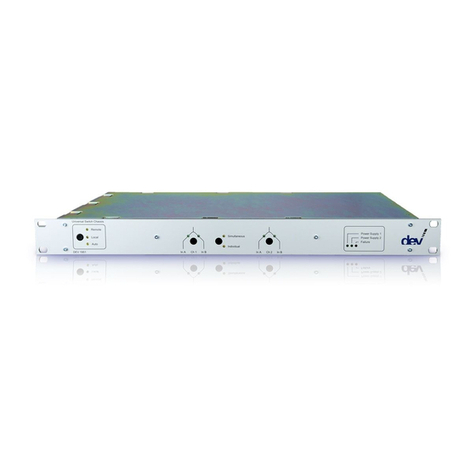
DEV 1953 User manual

User Manual
DEV 1953
Universal Switch Chassis 3 RU
DEV Systemtechnik GmbH
Grüner Weg 4A
61169 Friedberg
GERMANY
Tel: +49 6031 6975 100
Fax: +49 6031 6975 114
support@dev-systemtechnik.com
www.dev-systemtechnik.com
Revision: 2017-09-25
DEV 91-0120-B

User Manual DEV 1953
2 Copyright DEV Systemtechnik GmbH 2015-2017
Table of Contents
1Revision History----------------------------------------------------------- 7
2Introduction---------------------------------------------------------------- 8
2.1 Warranty---------------------------------------------------------------------------------- 8
2.2 Limitation of Warranty---------------------------------------------------------------- 8
2.3 Warnings---------------------------------------------------------------------------------- 8
3Product Description -----------------------------------------------------10
3.1 Features and Options---------------------------------------------------------------- 10
3.1.1 Device Panel---------------------------------------------------------------------------- 10
3.1.2 Communication Features ----------------------------------------------------------- 11
3.1.3 Autonomous Switching and Options --------------------------------------------- 12
3.1.4 Digital Interface Options ------------------------------------------------------------ 12
3.1.5 TRAC Option---------------------------------------------------------------------------- 12
3.1.6 Other Options-------------------------------------------------------------------------- 13
3.2 Modules Description ---------------------------------------------------------------- 13
3.2.1 DEV 11–0014--------------------------------------------------------------------------- 14
3.2.2 DEV 11-0026 --------------------------------------------------------------------------- 14
3.2.3 DEV 11-0031 --------------------------------------------------------------------------- 15
3.2.4 DEV 11-0034 --------------------------------------------------------------------------- 15
3.2.5 DEV 11-0051 --------------------------------------------------------------------------- 16
3.2.6 DEV 11-0097 --------------------------------------------------------------------------- 16
3.2.7 DEV 11-0102 --------------------------------------------------------------------------- 17
3.2.8 DEV 11-0105 --------------------------------------------------------------------------- 17
3.2.9 DEV 11-0110 --------------------------------------------------------------------------- 18
3.2.10 DEV 13-0033 --------------------------------------------------------------------------- 18
3.2.11 DEV 13-0063 --------------------------------------------------------------------------- 19
3.2.12 DEV 13-0235 --------------------------------------------------------------------------- 19
3.2.13 DEV 13-0321 --------------------------------------------------------------------------- 20
3.2.14 DEV 14-0052 --------------------------------------------------------------------------- 20
3.2.15 DEV 14-0089 --------------------------------------------------------------------------- 21
3.2.16 DEV 14-0090 --------------------------------------------------------------------------- 21
3.2.17 DEV 14-0092 --------------------------------------------------------------------------- 22
3.2.18 DEV 14-0094 --------------------------------------------------------------------------- 22
3.2.19 DEV 14-0096 --------------------------------------------------------------------------- 23
3.2.20 DEV 14-0103 --------------------------------------------------------------------------- 23
3.2.21 DEV 14-0111 --------------------------------------------------------------------------- 24
3.2.22 DEV 7462-------------------------------------------------------------------------------- 24
3.2.23 DEV 7463-------------------------------------------------------------------------------- 25
3.2.24 CPU Module ---------------------------------------------------------------------------- 25
3.2.25 Power Supply Modules -------------------------------------------------------------- 26
3.2.26 Digital Interface Modules ----------------------------------------------------------- 26

User Manual DEV 1953
Copyright DEV Systemtechnik GmbH 2015-2017 3
3.3 Product Drawings--------------------------------------------------------------------- 27
3.3.1 Front Side DEV 1953 ----------------------------------------------------------------- 27
3.3.2 Rear Side DEV 1953 with 5 Modules (Demo Application) ------------------- 28
3.3.3 Rear Side DEV 1953 with 12 Modules (RF Switching Application)--------- 28
3.3.4 Rear Side DEV 1953 with 16 Modules (Digital Switching Application)---- 29
4Installation Instructions------------------------------------------------29
4.1 Scope of Delivery --------------------------------------------------------------------- 29
4.2 Installation of the Product --------------------------------------------------------- 29
4.2.1 Mechanical Assembly ---------------------------------------------------------------- 29
4.2.2 Grounding, Data Cables, and Power Connection ------------------------------ 29
4.2.3 Connection of Optical Signal Cables ---------------------------------------------- 31
4.2.4 Connection of RF Signal Cables ---------------------------------------------------- 31
4.2.5 Installation and Exchange of Modules ------------------------------------------- 32
4.2.5.1 Exchange of the Micro-SD Card and Backup of the Configuration Data -----------33
4.2.6 Reset of the Device and the Restore of Factory Defaults ------------------- 33
4.3 Device Factory Settings ------------------------------------------------------------- 34
4.3.1 Factory Settings for Sensing Switch Modules ---------------------------------- 34
4.3.2 Factory Communication Protocol Configuration ------------------------------ 34
4.3.3 Factory Network Settings ----------------------------------------------------------- 34
4.3.4 Factory SNMP Settings--------------------------------------------------------------- 35
4.3.5 Factory Sandar Prosan Protocol Settings---------------------------------------- 35
4.3.6 Factory Leitch Protocol Settings --------------------------------------------------- 35
4.3.7 Factory QEC Protocol Settings ----------------------------------------------------- 35
4.4 Communication Interface Configuration --------------------------------------- 35
4.4.1 Serial Interface------------------------------------------------------------------------- 35
4.4.1.1 Standard Serial Interface Configuration ---------------------------------------------------36
4.4.1.2 Sandar Prosan Protocol Serial Interface Configuration --------------------------------36
4.4.2 Ethernet Interface -------------------------------------------------------------------- 36
4.4.2.1 Ethernet Connection----------------------------------------------------------------------------36
4.4.2.2 Network Setup via the Serial Interface-----------------------------------------------------37
4.4.2.2.1 Start and Termination of the Configuration Program ----------------------------------------------37
4.4.2.2.2 1 set IP address -----------------------------------------------------------------------------------------------39
4.4.2.2.3 2 set netmask -------------------------------------------------------------------------------------------------39
4.4.2.2.4 3 set gateway--------------------------------------------------------------------------------------------------39
4.5 Maintenance of the Product------------------------------------------------------- 39
5Operation of the Product ----------------------------------------------40
5.1 Modes of Operation ----------------------------------------------------------------- 40
5.1.1 Local Mode ----------------------------------------------------------------------------- 40
5.1.2 Remote Mode ------------------------------------------------------------------------- 40
5.1.3 Auto Mode ----------------------------------------------------------------------------- 41
5.1.3.1 Autonomous Switching Functionality ------------------------------------------------------41
5.1.4 Individual/Simultaneous Switching Mode -------------------------------------- 44

User Manual DEV 1953
4 Copyright DEV Systemtechnik GmbH 2015-2017
5.2 Initialization of the Device --------------------------------------------------------- 45
5.3 Operation via the Device Panel --------------------------------------------------- 45
5.4 Control via the Digital Interface Options --------------------------------------- 46
5.5 Operation via Web Interface ------------------------------------------------------ 46
5.5.1 Start of the Web Interface---------------------------------------------------------- 47
5.5.2 The Main Window and Common Features of the Main Tabs--------------- 49
5.5.3 Status Tab------------------------------------------------------------------------------- 50
5.5.4 Control Tab ----------------------------------------------------------------------------- 51
5.5.4.1 Group-----------------------------------------------------------------------------------------------53
5.5.4.2 Switch ----------------------------------------------------------------------------------------------56
5.5.4.3 Distribution Amplifier --------------------------------------------------------------------------59
5.5.5 Events Tab ------------------------------------------------------------------------------ 60
5.5.6 Recording Tab-------------------------------------------------------------------------- 61
5.5.7 Setup Tab ------------------------------------------------------------------------------- 65
5.5.7.1 User Setup-----------------------------------------------------------------------------------------66
5.5.7.1.1 Password and Language------------------------------------------------------------------------------------66
5.5.7.1.2 User Management -------------------------------------------------------------------------------------------66
5.5.7.2 System Setup -------------------------------------------------------------------------------------68
5.5.7.2.1 Network---------------------------------------------------------------------------------------------------------68
5.5.7.2.2 SNMP ------------------------------------------------------------------------------------------------------------69
5.5.7.2.3 CPH---------------------------------------------------------------------------------------------------------------70
5.5.7.3 Feature Setup-------------------------------------------------------------------------------------72
5.5.7.3.1 Recording-------------------------------------------------------------------------------------------------------72
5.5.7.3.2 Auto Mode -----------------------------------------------------------------------------------------------------73
5.5.7.3.3 Group Assignment -------------------------------------------------------------------------------------------75
5.5.7.3.4 Time Based Switching ---------------------------------------------------------------------------------------76
5.5.7.3.5 TRAC -------------------------------------------------------------------------------------------------------------79
5.5.7.3.5.1 TRAC Setup-----------------------------------------------------------------------------------------------------80
5.5.7.3.5.2 IP Monitor------------------------------------------------------------------------------------------------------84
5.5.7.3.5.3 Trap Log---------------------------------------------------------------------------------------------------------85
5.5.7.3.6 Actions ----------------------------------------------------------------------------------------------------------86
5.5.7.3.6.1 Switching Actions --------------------------------------------------------------------------------------------86
5.5.7.3.6.2 Action Log ------------------------------------------------------------------------------------------------------88
5.5.7.4 Software Service ---------------------------------------------------------------------------------89
5.5.7.4.1 Restore Factory Defaults -----------------------------------------------------------------------------------89
5.5.7.4.2 Data Backup ---------------------------------------------------------------------------------------------------89
5.5.7.4.3 Firmware Update---------------------------------------------------------------------------------------------93
5.5.8 Info Tab---------------------------------------------------------------------------------- 94
5.6 Control via Remote Interface: Sandar Prosan Protocol--------------------- 95
5.6.1 Sandar Prosan Protocol Overview ------------------------------------------------ 95
5.6.2 Sandar Prosan Protocol Communication Structure --------------------------- 95
5.6.3 Sandar Prosan Commands ---------------------------------------------------------- 96
5.6.3.1 Status Query (Q) ---------------------------------------------------------------------------------96
5.6.3.2 Query Alarm Messages (AM or AMA) ------------------------------------------------------96
5.6.3.3 System Identification (XR)---------------------------------------------------------------------97
5.6.3.4 Read Status of Signal Path (S or SA)---------------------------------------------------------97
5.6.3.5 Set Signal Path (M) ------------------------------------------------------------------------------98
5.6.3.6 Select Remote Control Mode (PMCI/PMCE)----------------------------------------------98

User Manual DEV 1953
Copyright DEV Systemtechnik GmbH 2015-2017 5
5.6.3.7 Select Echo in Local Mode (PME0/PME1)-------------------------------------------------98
5.6.3.8 Select Switching Operation Mode (PMOI/PMOS) ---------------------------------------99
5.6.3.9 Select Power Supply Monitoring Mode (PMP0/PMP1) --------------------------------99
5.7 Control via Remote Interface: Leitch Protocol -------------------------------100
5.7.1 Leitch Protocol Overview ----------------------------------------------------------100
5.7.2 Leitch Protocol Communication Structure -------------------------------------101
5.7.3 Leitch Telnet Authentication ------------------------------------------------------102
5.7.4 Leitch Commands --------------------------------------------------------------------102
5.7.4.1 Enable Reporting (?) -------------------------------------------------------------------------- 102
5.7.4.2 Alarms Request (Q?)-------------------------------------------------------------------------- 102
5.7.4.3 Device Description Request (I?A)---------------------------------------------------------- 103
5.7.4.4 Device Version Request (I?V)--------------------------------------------------------------- 103
5.7.4.5 Request Crosspoint Status (S?{Lvl}) ------------------------------------------------------- 104
5.7.4.5.1 Individual Switching Mode with Individual Switch Level Assignment Enabled ------------ 104
5.7.4.5.2 Individual Switch Level Assignment Disabled------------------------------------------------------- 104
5.7.4.6 Direct Crosspoint Take (X:)------------------------------------------------------------------ 105
5.7.4.6.1 Individual Switching Mode with Individual Switch Level Assignment Enabled ------------ 106
5.7.4.6.2 Individual Switch Level Assignment Disabled------------------------------------------------------- 106
5.8Control via Remote Interface: QEC Protocol ---------------------------------107
5.8.1 QEC Protocol Overview -------------------------------------------------------------107
5.8.2 QEC Protocol Communication Structure ---------------------------------------107
5.8.3 QEC Commands ----------------------------------------------------------------------109
5.8.3.1 Check Change Flag / Unit Status (C)------------------------------------------------------- 109
5.8.3.2 Check Queue (Q)------------------------------------------------------------------------------- 110
5.8.3.3 Firmware Version / Unit ID (F) ------------------------------------------------------------- 111
5.8.3.4 Query Output Channel (O) ------------------------------------------------------------------ 111
5.8.3.5 Set Crosspoint (S)------------------------------------------------------------------------------ 112
5.9 Control via Remote Interface: SNMP-------------------------------------------113
5.9.1 SNMP Overview ----------------------------------------------------------------------113
5.9.2 Private Enterprise Number, Device Index Number --------------------------113
5.9.3 The Switch MIB Tree ----------------------------------------------------------------114
5.9.4 MIB Objects ---------------------------------------------------------------------------114
5.9.4.1 .devSwitchTraps ------------------------------------------------------------------------------- 115
5.9.4.1.1 .devSwitchTraps.trapAlarmText------------------------------------------------------------------------ 115
5.9.4.1.2 .devSwitchTraps.trapAlarm------------------------------------------------------------------------------ 115
5.9.4.1.3 .devSwitchTraps.trapModeChange-------------------------------------------------------------------- 115
5.9.4.2 .instrument-------------------------------------------------------------------------------------- 116
5.9.4.2.1 .instrument.controllerMac ------------------------------------------------------------------------------ 116
5.9.4.2.2 .instrument.firmwareRevision -------------------------------------------------------------------------- 116
5.9.4.2.3 .instrument.instrumentType ---------------------------------------------------------------------------- 116
5.9.4.2.4 .instrument.antennaControllerType ------------------------------------------------------------------ 116
5.9.4.3 .application-------------------------------------------------------------------------------------- 117
5.9.4.3.1 .application.controlMode-------------------------------------------------------------------------------- 117
5.9.4.3.2 .application.switchingControl--------------------------------------------------------------------------- 117
5.9.4.3.3 .application.simultaneousMode ----------------------------------------------------------------------- 118
5.9.4.3.4 .application.numberOfSwitchGroups----------------------------------------------------------------- 118
5.9.4.3.5 .application.switchGroupTable ------------------------------------------------------------------------- 118
5.9.4.3.5.1 .application.switchGroupTable.switchGroupEntry.swGroupIndex --------------------------- 118

User Manual DEV 1953
6 Copyright DEV Systemtechnik GmbH 2015-2017
5.9.4.3.5.2 .application.switchGroupTable.switchGroupEntry.swGroupMembers---------------------- 119
5.9.4.3.5.3 .application.switchGroupTable.switchGroupEntry.swMainRfStatus ------------------------- 119
5.9.4.3.5.4 .application.switchGroupTable.switchGroupEntry.swRedundancyRfStatus --------------- 120
5.9.4.3.6 .application.numberOfSwitchUnits-------------------------------------------------------------------- 120
5.9.4.3.7 .application.switchUnitTable---------------------------------------------------------------------------- 120
5.9.4.3.7.1 .application.switchUnitTable.switchUnitEntry.swIndex ----------------------------------------- 120
5.9.4.3.7.2 .application.switchUnitTable.switchUnitEntry.swSize-------------------------------------------- 121
5.9.4.3.7.3 .application.switchUnitTable.switchUnitEntry.swMembers------------------------------------ 121
5.9.4.3.7.4 .application.switchUnitTable.switchUnitEntry.swPosition-------------------------------------- 121
5.9.4.3.8 .application.numberOfPorts----------------------------------------------------------------------------- 122
5.9.4.3.9 .application.portTable ------------------------------------------------------------------------------------ 122
5.9.4.3.9.1 .application.portTable.portEntry.portIndex -------------------------------------------------------- 123
5.9.4.3.9.2 .application.portTable.portEntry.poEnable --------------------------------------------------------- 123
5.9.4.3.9.3 .application.portTable.portEntry.poType------------------------------------------------------------ 123
5.9.4.3.9.4 .application.portTable.portEntry.poHasRfSense--------------------------------------------------- 124
5.9.4.3.9.5 .application.portTable.portEntry.poRfSense-------------------------------------------------------- 124
5.9.4.3.9.6 .application.portTable.portEntry.poRfLimit--------------------------------------------------------- 124
5.9.4.3.9.7 .application.portTable.portEntry.poHasBias-------------------------------------------------------- 124
5.9.4.3.9.8 .application.portTable.portEntry.poBiasOnOff----------------------------------------------------- 124
5.9.4.3.9.9 .application.portTable.portEntry.poBiasCurrent -------------------------------------------------- 124
5.9.4.3.9.10 .application.portTable.portEntry.poBiasLimitLo--------------------------------------------------- 125
5.9.4.3.9.11 .application.portTable.portEntry.poBiasLimitHi --------------------------------------------------- 125
5.9.4.3.9.12 .application.portTable.portEntry.poHasGain ------------------------------------------------------- 125
5.9.4.3.9.13 .application.portTable.portEntry.poGain ------------------------------------------------------------ 125
5.9.4.3.9.14 .application.portTable.portEntry.poHasTilt --------------------------------------------------------- 125
5.9.4.3.9.15 .application.portTable.portEntry.poTilt -------------------------------------------------------------- 125
5.9.4.3.9.16 .application.portTable.portEntry.poCardType ----------------------------------------------------- 126
5.9.4.3.9.17 .application.portTable.portEntry.poSlot ------------------------------------------------------------- 126
5.9.4.3.9.18 .application.portTable.portEntry.poRfSenseStatus ----------------------------------------------- 126
5.9.4.3.9.19 .application.portTable.portEntry.poBiasStatus ---------------------------------------------------- 126
5.9.4.3.9.20 .application.portTable.portEntry.poLightStatus --------------------------------------------------- 126
5.9.4.3.9.21 .application.portTable.portEntry.poCardStatus --------------------------------------------------- 127
5.9.4.3.10 .application.antennaStatus------------------------------------------------------------------------------ 127
5.9.4.3.11 .application.antennaPosition --------------------------------------------------------------------------- 127
5.9.4.4 .surveillance------------------------------------------------------------------------------------- 128
5.9.4.4.1 .surveillance.trapEnableMask--------------------------------------------------------------------------- 129
5.9.4.4.2 .surveillance.errorEnableMask ------------------------------------------------------------------------- 129
5.9.4.4.3 .surveillance.numberOfErrors -------------------------------------------------------------------------- 130
5.9.4.4.4 .surveillance.errorTable ---------------------------------------------------------------------------------- 130
5.9.4.4.4.1 .surveillance.errorTable.errorEntry.errorIndex ---------------------------------------------------- 130
5.9.4.4.4.2 .surveillance.errorTable.errorEntry.errorNr -------------------------------------------------------- 130
5.9.4.4.4.3 .surveillance.errorTable.errorEntry.errorCount---------------------------------------------------- 130
5.9.4.4.4.4 .surveillance.errorTable.errorEntry.errorDateTime----------------------------------------------- 131
5.9.4.4.4.5 .surveillance.errorTable.errorEntry.errorPending------------------------------------------------- 131
5.9.4.4.4.6 .surveillance.errorTable.errorEntry.errorAcknowledge------------------------------------------ 131
5.9.4.4.5 .surveillance.numberOfPowerLines ------------------------------------------------------------------- 131
5.9.4.4.6 .surveillance.powerLineTable --------------------------------------------------------------------------- 131
5.9.4.4.6.1 .surveillance.powerLineTable.powerLineEntry.powerLineIndex ------------------------------ 131
5.9.4.4.6.2 .surveillance.powerLineTable.powerLineEntry.powerLineStatus ----------------------------- 131
5.9.4.4.7 .surveillance.numberOfPowerSupplies--------------------------------------------------------------- 132
5.9.4.4.8 .surveillance.powerSupplyTable ----------------------------------------------------------------------- 132
5.9.4.4.8.1 .surveillance.powerSupplyTable.powerSupplyEntry.powerSupplyIndex-------------------- 132
5.9.4.4.8.2 .surveillance.powerSupplyTable.powerSupplyEntry.powerSupplyStatus------------------- 132
5.9.4.4.9 .surveillance.numberOfFans ---------------------------------------------------------------------------- 132

User Manual DEV 1953
Copyright DEV Systemtechnik GmbH 2015-2017 7
5.9.4.4.10 .surveillance.fanTable------------------------------------------------------------------------------------- 132
5.9.4.4.10.1 .surveillance.fanTable.fanEntry.fanIndex------------------------------------------------------------ 133
5.9.4.4.10.2 .surveillance.fanTable.fanEntry.fanStatus----------------------------------------------------------- 133
5.9.4.4.11 .surveillance.internalDeviceStatus--------------------------------------------------------------------- 133
5.9.4.4.12 .surveillance.externalDeviceStatus -------------------------------------------------------------------- 133
5.9.4.4.13 .surveillance.supportHardwareStatus ---------------------------------------------------------------- 133
5.9.4.4.14 .surveillance.errorDescription -------------------------------------------------------------------------- 133
6Event Indication -------------------------------------------------------- 134
6.1 Software Event Indication---------------------------------------------------------134
6.1.1 Power Events--------------------------------------------------------------------------134
6.1.2 Switch Module Events --------------------------------------------------------------134
6.1.3 Input Module Events ----------------------------------------------------------------134
6.1.4 Digital Interface Events -------------------------------------------------------------135
6.1.5 RF Level Monitoring Events--------------------------------------------------------135
6.1.6 Digital Signal Quality Events-------------------------------------------------------135
6.1.7 Other Events --------------------------------------------------------------------------135
7Connectors -------------------------------------------------------------- 136
8Technical Data and Options ----------------------------------------- 138
9Spare Parts -------------------------------------------------------------- 138
10 Conformance Declarations ------------------------------------------ 138
10.1 Certificate of Conformance -------------------------------------------------------138
10.2 EU Declaration of Conformity ----------------------------------------------------141
11 Glossary ------------------------------------------------------------------ 142
12 Notes---------------------------------------------------------------------- 143
1Revision History
Revision (Date)
Author
Short Description
A (12-Nov-2015)
WP
Initial version
B (25-Sep-2017)
WP
Complete rework to new document format

User Manual DEV 1953
8 Copyright DEV Systemtechnik GmbH 2015-2017
2Introduction
Thank you for purchasing a DEV 1953 Universal Switch Chassis. This user manual is
intended to familiarize you with the installation and operation of the product.
The DEV 1953 chassis for professional use can be equipped with modules with the
same or with different functionalities, to realize a switching solution for up to
16 channels. There is a large selection of switch modules for different applications;
in addition, there are available some modules without switching functionality that
can be applied to the DEV 1953 chassis as well.
DEV Systemtechnik GmbH declares that this equipment meets all relevant
standards and rules. The unit carries a CE mark.
Please read all instructions before installation or usage of the product!
2.1 Warranty
The product has a warranty against defects in material and workmanship for a
period of two years from the date of shipment.
During the warranty period DEV Systemtechnik will, at its option, either repair or
replace the product if it turns out to be defective.
For warranty, service, or repair, the product must be returned to DEV System-
technik. The customer has to pay shipping charges to DEV Systemtechnik and
DEV Systemtechnik will pay shipping charges to return the product to the customer.
However, the customer is obliged to pay all duties, all taxes, and all other additional
costs arising from the shipment of the product.
DEV Systemtechnik warrants that the software and firmware designated by
DEV Systemtechnik for use with the product will execute its programming
instructions if installed properly. DEV Systemtechnik does not warrant that the
operation of the product, software, or firmware will be uninterrupted or error-free.
2.2 Limitation of Warranty
The preceding warranty does not apply to defects resulting from:
improper site preparation or site maintenance;
improper or inadequate interfacing of the product;
unauthorized modification or misuse of the product;
the application of software supplied by the customer;
improper or inadequate maintenance of the product;
operation beyond the environmental conditions specified for the product.
2.3 Warnings
The following safety measures must be observed during all phases of operation,
service, and repair of the device. Failure to comply with the safety precautions or
warnings in this document violates safety standards of design, manufacturing, and
intended use of the device and may affect the built-in protections. DEV System-
technik shall not be liable for the user's failure to comply with these requirements.
Disconnect the device from any external power line before opening of the housing.
In any case, the device is to be opened by trained service staff, only.

User Manual DEV 1953
Copyright DEV Systemtechnik GmbH 2015-2017 9
Environmental Conditions
The device is designed for indoor use and for an ambient temperature range.
Mechanical Integration
It is not permitted to fix the chassis on the rack mount flanges, only. Balanced
weight distribution of the chassis has to be ensured by placing it on a solid surface
or by using rack rails.
Sufficient airflow through the chassis must be ensured to achieve best cooling
results. Do not block or obstruct the airflow through the chassis at the front and at
the rear side, e.g. by placing large components close to the rear side.
Grounding, AC Connection, Cables
To minimize shock hazard the device must be connected to an electrical ground via
a ground wire, please refer to chapter 4.2.2.
For the AC connection, the device must be connected to the AC power supply
mains through two power cables with three conductors and with the ground wire
firmly connected to an electrical ground (safety ground) at the power outlet. Any
interruption of the protective ground conductor will cause a potential shock hazard
that might cause personal injury.
Risk of electrical shock and energy hazard:
Disconnecting a single power supply line only does not interrupt the AC supply
(with Option 14: DC supply) of the device. To isolate the device completely,
disconnect both power supply lines.
Do not connect the device to AC mains supply exceeding the specifications for input
voltage and frequency. The recommended AC cables to be applied are standard
high temperature power cables with type IEC 60320-C13 appliance plug appro-
priately rated to the conditions of the country where the device is operated.
With applied Option 14, the device is supplied with DC voltage instead of AC mains.
In this case, do not connect the device to DC mains supply exceeding the
specifications for input voltage. For the DC supply wiring use cables with an
appropriate wire size. The pin assignment of the DC supply connector is stated in
chapter 7.
Laser Safety (applies if equipped with Optical Switch Modules DEV 7462, DEV 7463)
Safety of Laser Products
DEV Systemtechnik recommends following the governing standard of the
country where the product is operated to assure regulatory compliance and to
provide the necessary safety programs to protect the operators and other
persons who get in contact with the product.
It is recommended to power down the product while working on the optical
fiber wiring.
The optical modules installed in the product operate with light at a non-visible
wavelength. Highest caution has to be taken, since the modules may carry laser
light that is capable to harm the human eye!
If no optical fiber is (to be) connected to an optical module, the optical con-
nector(s) have to be equipped with the appropriate protection cover(s).
Direct exposure to the beam is to be avoided, i.e. do not look into
unterminated optical ports or at fibers that connect to unknown sources.

User Manual DEV 1953
10 Copyright DEV Systemtechnik GmbH 2015-2017
3Product Description
With the DEV 1953, DEV Systemtechnik has developed a modular design principle
for a universal switch chassis. A variety of different switch modules is available that
can be installed easily in the 16 slots of the device. A selection of passive splitter
modules and of distribution amplifier modules for ASI/SDI signals is available as
well. Please refer to chapter 3.2 for the description of the single modules.
A device panel (chapter 3.1.1) permits the monitoring and the local control of the
DEV 1953. Some other methods for the control and for the surveillance of the
device are provided (chapter 3.1.2). The application of sensing switch modules and
of digital signal switch modules enables additional autonomous switching
capabilities of the DEV 1953 (chapter 3.1.3) as well as the application of the TRAC
(stands for "Trap Receiver Action Controller") option (chapter 3.1.5).
3.1 Features and Options
3.1.1 Device Panel
Aside from the device panel -which is explained in the following- the product
provides the "Reset" push button on the CPU module (please refer to chapter 3.2.24)
for restarting the device, and the two LEDs on each power supply module
(chapter 3.2.25).
The device panel occupies most of the space at the front side of the chassis:
3
1 2 4 5 6 78 9 10 11 12 13 14 15 16
Sim ultaneous
Rem ote
Individual
Local Auto
In A
In B
Universal Switch C hassis
DEV 1953
34 5 678
The mode push button (3) permits the change of the operation mode (chapter 5.1)
at the device. By pressing and holding the push button for ~3 seconds the status of
the LEDs advances, i.e. always only one of the operation mode LEDs "Remote" (4),
"Local" (5), or "Auto" (6) is on.
The second functionality of the mode push button is the event acknowledgment:
If there are pending and not acknowledged event(s), this is indicated via continuous
alternate blinking of all channel LEDs. To acknowledge the event(s) (i.e. to stop the
blinking of the LEDs) at the device, the mode push button is to be operated. Thus,
three scenarios for the behavior of the mode push button are to be considered:
1. There are no pending and not acknowledged event(s):
In this case, the operation mode can be altered as described above.
2. There are pending and not acknowledged event(s) in Local Mode:
A short operation of the mode push button acknowledges the event(s) (stops
the blinking of the LEDs). After that, the operation mode can be altered as
described above.

User Manual DEV 1953
Copyright DEV Systemtechnik GmbH 2015-2017 11
3. Pending and not acknowledged event(s) in Remote Mode (or Auto Mode):
A short operation of the mode push button acknowledges the event(s) (stops
the blinking of the LEDs) and switches the device to Local Mode. After that, the
operation mode can be altered as described above.
Note:
Usually the type of event causing the event indication via device panel can be
identified via Web Interface or via remote interface, only.
If event(s) are not acknowledged yet, the alternate blinking of all channel LEDs
is performed synchronously but according to the switching status of the device.
If an event is not acknowledged and if the event disappears (e.g. a detected
missing AC line is working again), the event indication via device panel will stop
automatically (if it is the sole event).
The event indication via device panel cannot be stopped if no switch (or
distribution amplifier) module is installed or detected within the device.
With the sixteen channel push buttons (indicated by 7in the figure above) labeled
"1"…"16", one of the two (input) ports (primary (input) port "In A" or secondary
(input) port "In B") of a switch module can be switched to the common (output) port
in Local Mode (!). The (input) port that is currently active is indicated via the related
green channel LED.
The switching mode push button and the yellow LEDs labeled "Simultaneous" and
"Individual" (indicated by 8in the figure above) are for the Simultaneous/Individual
switching mode functionality of the device, which is described in chapter 5.1.4.
To alter the routing of a single switch module via the related channel push button
make sure that the device is in Local Mode and that the "Individual" LED is lit. After
the operation of the desired channel push button, the LED display will indicate the
altered switching position as a receipt.
If the "Simultaneous" LED is lit (for the preconditions to activate Simultaneous
switching mode please refer to chapter 5.1.4), any of the channel push buttons of a
group can be operated to initiate the switching of the switch modules being
member of the group.
Note:
The channel push buttons (7) and the switching mode push button (8) are
enabled in Local Mode, only.
The related channel push button (7) is not functional (i.e. the LED always
indicates position "In A") if a slot is not equipped with a switch module.
3.1.2 Communication Features
In addition to the device panel there are provided some options for the monitoring
and control of the product:
The Web Interface (please refer to chapter 5.5) provides features for checking the
health status and for changing the setup of the device; it enables full control in
terms of switching and in terms of setting up specific parameters. Additionally, the
features Time Based Switching and TRAC (if installed), and -for devices with
installed sensing switch modules- the recording functionality are accessible.
The implementation of SNMP (Simple Network Management Protocol) via the
Ethernet interface is intended to serve as the standard for remote monitoring and
control of the device (chapter 5.9).

User Manual DEV 1953
12 Copyright DEV Systemtechnik GmbH 2015-2017
In addition, a Communication Protocol Handler (CPH) is implemented which
enables the use of one of the following remote protocols with different monitoring
and control capabilities:
Sandar Prosan protocol via serial interface (chapter 5.6);
Leitch protocol via serial interface and via Ethernet interface (chapter 5.7); and
QEC protocol via serial interface and via Ethernet interface (chapter 5.8).
The installation of sensing switch modules and of digital signal switch modules
enables the autonomous switching capability (chapter 3.1.3) of the device based on
the signal quality. Moreover, the TRAC option (chapter 3.1.5) permits a remote
device to control the switching of the DEV 1953.
Finally, the digital interface options (chapter 3.1.4) feature basic remote switching
functionality permitting the control of the device.
3.1.3 Autonomous Switching and Options
Among the broad choice of other switch modules, the DEV 1953 can be equipped
with sensing switch modules and/or with digital signal switch modules.
The sensing switch modules (and the digital signal switch modules) are special since
they permit the device to switch autonomously (please refer to chapter 5.1.3)
based on the RF level information (and on the digital signal quality information,
respectively) at both input ports of the module.
By default, the DEV 1953 provides autonomous switching capability from the
primary to the secondary input port(s).
With Option 22, the DEV 1953 is delivered with the main backup swap feature, i.e.
the autonomous switching works in both directions instead of switching from the
primary to the secondary input port(s), only.
With Option 28 the DEV 1953 is delivered with the automatic switch back feature
which permits the autonomous switching in both directions as well, but with an
adjustable hysteresis (for sensing switch modules) or with an adjustable delay (for
digital signal switch modules) when switching back from the secondary to the
primary input port(s).
The Web Interface enables the adjustment of the RF threshold levels for each input
port of a sensing switch module and enables the modification of settings for the
automatic switch back option.
3.1.4 Digital Interface Options
As an option (Option 56 for 24 V and Option 57 for 12 V) the product is equipped
with a digital interface module (please refer to chapter 3.2.26), e.g. to be
connected to a PLC (Programmable Logic Control).
With this interface, it is possible to switch up to 16 channels of the device and to
obtain switching status information for each channel.
3.1.5 TRAC Option
The DEV 1953 can be equipped with the TRAC (stands for Trap Receiver Action
Controller) option (Option 37), which permits the remote controlled switching of
the product based on SNMP traps, or based on the availability or on the absence of
a remote device (IP Monitoring). For more details, please refer to chapter 5.5.7.3.5.

User Manual DEV 1953
Copyright DEV Systemtechnik GmbH 2015-2017 13
3.1.6 Other Options
By default, the DEV 1953 is delivered with two redundant wide range AC power
supplies that are connected to separate AC lines. Option 14 permits a redundant
DC supply of the device supplied by two different lines with -36...-75 V DC input
voltage (or with +36...+75 V DC by inverting the polarity).
A single license for the Web Interface (please refer to chapter 5.5) is included in the
delivery of the product, additional licenses can be ordered initially via Option 78.
Note that it is possible to purchase additional license keys at any time, please
contact DEV Systemtechnik.
3.2 Modules Description
This paragraph points out the functionality of the modules that were designed for
the DEV 1953. There are available electrical and optical switch modules, passive
splitter modules, and distribution amplifier modules for ASI/SDI signals.
The modules described in the following can be removed, installed, and/or ex-
changed even during the operation of the device. Knurled head screws are pro-
vided on each module, which can be operated easily.
A short listing of the available DEV 1953 modules is provided here for reference:
3.2.1 DEV 11-0014 - DPST Sensing Switch Module; DC, 950…2150 MHz; 50 Ohm, SMA (f)
3.2.2 DEV 11–0026 - DPST Sensing Switch Module; DC, 950…2150 MHz; 75 Ohm, F (f)
3.2.3 DEV 11–0031 - DPST Switch Module with Monitor Port; 47...1006 MHz; 75 Ohm, BNC (f)
3.2.4 DEV 11–0034 - DPST Sensing Switch Module; DC, 47...1006 MHz; 75 Ohm, F (f)
3.2.5 DEV 11–0051 - DPST Switch Module; DC…2500 MHz; 50 Ohm, SMA (f)
3.2.6 DEV 11–0097 - DPST Switch Module without Monitor Port; 47...1500 MHz; 75 Ohm, BNC (f)
3.2.7 DEV 11–0102 - DPST High Power Sensing Switch Module; DC, 950…2150 MHz; 75 Ohm, F (f)
3.2.8 DEV 11–0105 - DPST High Power Sensing Switch Module; DC, 47…1006 MHz; 75 Ohm, F (f)
3.2.9 DEV 11–0110 - DPST Switch Module; DC, 47…2500 MHz; 75 Ohm, F (f)
3.2.10 DEV 13–0033 - 1:2/2:1 Splitter/Combiner Module, Passive; 950…2150 MHz; 75 Ohm, F (f)
3.2.11 DEV 13–0063 - 1:4/4:1 Splitter/Combiner Module, Passive; 950…2150 MHz; 75 Ohm, F (f)
3.2.12 DEV 13–0235 - 1:4/4:1 Splitter/Combiner Module, Passive; 47…1006 MHz; 75 Ohm, F (f)
3.2.13 DEV 13–0321 - 1:4/4:1 Splitter/Combiner Module, Passive; 47…1006 MHz; 75 Ohm, F (f)
3.2.14 DEV 14–0052 - Ethernet 2:1/1:2 Switch Module
3.2.15 DEV 14–0089 - DPST Switch Module with DA 1:3; ASI; 75 Ohm, BNC (f)
3.2.16 DEV 14–0090 - DPST Switch Module with DA 1:3; ASI / HD-SDI; 75 Ohm, BNC (f)
3.2.17 DEV 14–0092 - Distribution Amplifier 1:3; ASI; 75 Ohm, BNC (f)
3.2.18 DEV 14–0094 - DPST Switch Module with DA 1:3; ASI / 3G-SDI; 75 Ohm, BNC (f)
3.2.19 DEV 14–0096 - Distribution Amplifier 1:3; ASI / 3G-SDI; 75 Ohm, BNC (f)
3.2.20 DEV 14–0103 - Distribution Amplifier 1:3; ASI / HD-SDI; 75 Ohm, BNC (f)
3.2.21 DEV 14–0111 - DPST Switch Module with DA 1:3; E1/T1; 75 Ohm, BNC (f)
3.2.22 DEV 7462 - 1:2 Optribution® Switch; 1260…1360 nm & 1510…1610 nm; SC/APC
3.2.23 DEV 7463 - 1:2 Optribution® Switch 1:2; 1260…1610 nm; SC/APC
Finally, there are the descriptions for the DEV 1953 modules that are installed by
default or that can be installed as an option:
3.2.24 CPU Module
3.2.25 Power Supply Modules
3.2.26 Digital Interface Modules

User Manual DEV 1953
14 Copyright DEV Systemtechnik GmbH 2015-2017
3.2.1 DEV 11–0014
DPST Sensing Switch Module; DC, 950…2150 MHz; 50 Ohm, SMA (f)
Out
In A
In B
Logic External
Controller
2
3
1
In A
Out
In B
DEV 11-0014
Two input ports ("In A", "In B") can be switched to one output port ("Out"). The
unused input port is terminated internally. The module is able to pass an external
10 MHz reference signal.
The module provides RF level monitoring, i.e. the RF level of both input ports is
measured and is compared with (adjustable) RF threshold levels. This enables the
event indication functionality with respect to the present input signal levels, and/or
permits the DEV 1953 to control the switching autonomously.
3.2.2 DEV 11-0026
DPST Sensing Switch Module; DC, 950…2150 MHz; 75 Ohm, F (f)
Out
In A
In B
Logic External
Controller
2
3
1
In A
Out
In B
DEV 11-0026
The functionality of the module DEV 11-0026 is identical with the module
DEV 11-0014 (please refer to chapter 3.2.1), but the module is designed for 75 Ohm
with F connectors (instead of 50 Ohm with SMA connectors).

User Manual DEV 1953
Copyright DEV Systemtechnik GmbH 2015-2017 15
3.2.3 DEV 11-0031
DPST Switch Module with Monitor Port; 47...1006 MHz; 75 Ohm, BNC (f)
Monitor
In A
In B
Out
1
4
3
2
In B
Monitor
Out
In A
DEV 11-0031
The output port ("Out") can be switched to one of two input ports ("In A", "In B"). The
unused input port is terminated internally. The transmission is DC blocked. Failsafe
relays are used for switching. In the case of power loss, the primary input port
("In A") is routed to the output port. For measurement purposes, the monitoring
output port ("Monitor") is available.
3.2.4 DEV 11-0034
DPST Sensing Switch Module; DC, 47...1006 MHz; 75 Ohm, F (f)
Out
In A
In B
Logic External
Controller
2
3
1
In A
Out
In B
DEV 11-0034
The functionality of the module DEV 11-0034 is identical with the module
DEV 11-0014 (please refer to chapter 3.2.1), but the module is designed for a
different frequency range and for 75 Ohm with F connectors (instead of 50 Ohm
with SMA connectors).

User Manual DEV 1953
16 Copyright DEV Systemtechnik GmbH 2015-2017
3.2.5 DEV 11-0051
DPST Switch Module; DC…2500 MHz; 50 Ohm, SMA (f)
In A
In B
Out
1
3
2
In A
Out
In B
DEV 11-0051
The common port ("Out") can be switched to one of two input/output ports ("In A",
"In B"). The unused input/output port is terminated internally. Latching relays are
used for switching.
3.2.6 DEV 11-0097
DPST Switch Module without Monitor Port; 47...1500 MHz; 75 Ohm, BNC (f)
In A
In B
Out
1
3
2
In B
Out
In A
DEV 11-0097
The functionality of the module DEV 11-0097 is identical with the module
DEV 11-0031 (please refer to chapter 3.2.3), but without a monitor port thus
enabling an extended frequency range.

User Manual DEV 1953
Copyright DEV Systemtechnik GmbH 2015-2017 17
3.2.7 DEV 11-0102
DPST High Power Sensing Switch Module; DC, 950…2150 MHz; 75 Ohm, F (f)
Out
In A
In B
Logic External
Controller
2
3
1
In A
Out
In B
DEV 11-0102
The functionality of the module DEV 11-0102 is identical with the module
DEV 11-0014 (please refer to chapter 3.2.1), but the module is designed for high
power signals and for 75 Ohm with F connectors (instead of 50 Ohm with SMA
connectors).
3.2.8 DEV 11-0105
DPST High Power Sensing Switch Module; DC, 47…1006 MHz; 75 Ohm, F (f)
Out
In A
In B
Logic External
Controller
2
3
1
In A
Out
In B
DEV 11-0105
The functionality of the module DEV 11-0105 is identical with the module
DEV 11-0014 (please refer to chapter 3.2.1), but the module is designed for high
power signals, for a different frequency range, and for 75 Ohm with F connectors
(instead of 50 Ohm with SMA connectors).

User Manual DEV 1953
18 Copyright DEV Systemtechnik GmbH 2015-2017
3.2.9 DEV 11-0110
DPST Switch Module; DC, 47…2500 MHz; 75 Ohm, F (f)
In A
In B
Out
2
3
1
In A
Out
In B
DEV 11-0110
The common port ("Out") can be switched to one of two input/output ports ("In A",
"In B"). The unused input/output port is terminated internally. The module is able to
pass an external 10 MHz reference signal.
3.2.10 DEV 13-0033
1:2/2:1 Splitter/Combiner Module, Passive; 950…2150 MHz; 75 Ohm, F (f)
1
3
2
In Out 1
Out 2
In
Out 1
Out 2
DEV 13-0033
This passive module for splitting or for combining RF signals can be installed in a
DEV 1953 as a supplemental module.

User Manual DEV 1953
Copyright DEV Systemtechnik GmbH 2015-2017 19
3.2.11 DEV 13-0063
1:4/4:1 Splitter/Combiner Module, Passive; 950…2150 MHz; 75 Ohm, F (f)
1
5
4
In
Out 1
Out 2
Out 3
Out 4
3
2
DEV 13-0063
Out 1
Out 2
In
Out 3
Out 4
This passive module for splitting or for combining RF signals can be installed in a
DEV 1953 as a supplemental module.
3.2.12 DEV 13-0235
1:4/4:1 Splitter/Combiner Module, Passive; 47…1006 MHz; 75 Ohm, F (f)
1
5
4
In
Out 1
Out 2
Out 3
Out 4
3
2
DEV 13-0235
Out 1
Out 2
In
Out 3
Out 4
This passive module for splitting or for combining RF signals can be installed in a
DEV 1953 as a supplemental module.

User Manual DEV 1953
20 Copyright DEV Systemtechnik GmbH 2015-2017
3.2.13 DEV 13-0321
1:4/4:1 Splitter/Combiner Module, Passive; 950…2150 MHz; 50 Ohm, SMA (f)
1
5
4
In
Out 1
Out 2
Out 3
Out 4
3
2
Out 1
Out 2
In
Out 3
Out 4
DEV 13-0321
This passive module for splitting or for combining RF signals can be installed in a
DEV 1953 as a supplemental module.
3.2.14 DEV 14-0052
Ethernet 2:1/1:2 Switch Module
1:1 Patch Cable
1
8
LAN 1
LAN 2
WAN
1:1 Patch Cable
1:1 Patch Cable
1
8
1
8
8
1
8
1
8
1
1
2
3
DEV 14-0052
LAN 1
WAN
LAN 2
The module is designed for Ethernet switching applications and is equipped with
three RJ-45 Ethernet connectors in order to select physically one of two routes.
Table of contents
Other DEV Chassis manuals
Popular Chassis manuals by other brands

ATX
ATX MAXNET II Platinum Series Installation & operation manual

Overland Storage
Overland Storage NEO 200S Replacement instructions
Optical Systems Design
Optical Systems Design OSD350B Operation manual
Fortinet
Fortinet FortiGate-5000 Backplane communications guide
National Instruments
National Instruments CompactDAQ cDAQ-9185 user manual

Cisco
Cisco ONS 15454 DWDM Installation and operation guide

Agilent Technologies
Agilent Technologies U2781A quick start guide
NI
NI PXIe-1082DC user manual
Thermaltake
Thermaltake V4 Black VM3000 Series user manual
Intel
Intel C50277-001 user guide
IEI Technology
IEI Technology ECA-200 Quick installation guide

Changhong Electric
Changhong Electric LS18 Maintenance manual
