Keysight ixia XGS12 User manual

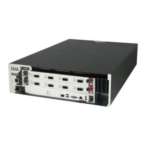
XGS12 Chassis Platform
Assembly Guide
Version 1.0
Release 8.40 EA,
November 2017

Copyright and Disclaimer
Copyright © 2017 Ixia. All rights reserved.
This publication may not be copied, in whole or in part, without Ixia's consent.
Ixia, the Ixia logo, and all Ixia brand names and product names in this document are
either trademarks or registered trademarks of Ixia in the United States and/or other coun-
tries. All other trademarks belong to their respective owners.
The information herein is furnished for informational use only, is subject to change by Ixia
without notice, and should not be construed as a commitment by Ixia. Ixia assumes no
responsibility or liability for any errors or inaccuracies contained in this publication.
RESTRICTED RIGHTS NOTICE
As prescribed by FAR 27.409(b)(4) and in accordance with FAR 52.227-14, please take
notice of the following.
(a) This proprietary computer software and/or software technical data is submitted with
restricted rights. It may not be used, reproduced, or disclosed by the Government
except as provided in paragraph (b) of this notice or as otherwise expressly stated in
the applicable contract.
(b) This computer software and/or software technical data may be—
(1) Used or copied for use with the computer(s) for which it was acquired, including
use at any Government installation to which the computer(s) may be transferred;
(2) Used or copied for use with a backup computer if any computer for which it was
acquired is inoperative;
(3) Reproduced for safekeeping (archives) or backup purposes;
(4) Modified, adapted, or combined with other computer software, provided that the
modified, adapted, or combined portions of the derivative software incorporating
any of the delivered, restricted computer software shall be subject to the same
restricted rights;
(5) Disclosed to and reproduced for use by support service Contractors or their sub-
contractors in accordance with paragraphs (b)(1) through (4) of this notice; and
(6) Used or copied for use with a replacement computer.
(c) Notwithstanding the foregoing, if this computer software and/or software technical
data is copyrighted computer software and/or software technical data, it is licensed to
the Government with the minimum rights set forth in paragraph (b) of this notice.
(d) Any other rights or limitations regarding the use, duplication, or disclosure of this
computer software and/or software technical data are to be expressly stated in, or
incorporated in, the applicable contract.
(e) This notice shall be marked on any reproduction of this computer software, in whole
or in part.
(End of notice)
ii XGS12 Chassis Platform Assembly Guide, Release 8.40 EA
Contacting Ixia
Contacting Ixia
Corporate
Headquarters
Ixia Worldwide Headquarters
26601 W. Agoura Rd.
Calabasas, CA 91302
USA
+1 877 FOR IXIA (877 367 4942)
+1 818 871 1800 (International)
(FAX) +1 818 871 1805
sales@ixiacom.com
Web site: www.ixiacom.com
General: info@ixiacom.com
Investor Relations: ir@ixiacom.com
Training: training@ixiacom.com
Support: support@ixiacom.com
+1 818 595 2599
EMEA Ixia Europe Limited
Part 2nd floor,
Clarion House, Norreys Drive
Maidenhead, UK SL6 4FL
+44 (1628) 408750
FAX +44 (1628) 639916
salesemea@ixiacom.com
Support: support-emea@ixiacom.com
+40 21 301 5699
Asia Pacific Ixia Pte Ltd
210 Middle Road
#08-01 IOI Plaza
Singapore 188994
Support: support-asiapac@ixi-
acom.com
+91 80 4939 6410
Japan Ixia KK
Nishi-Shinjuku Mitsui Bldg 11F
6-24-1, Nishi-Shinjuku, Shinjuku-ku
Tokyo 160-0023
Japan
Support: support-japan@ixiacom.com
+81 3 5326 1980
India Ixia Technologies Pvt Ltd
Tower 1, 7th Floor, UMIYA Business Bay
Cessna Business Park
Survey No. 10/1A, 10/2, 11 & 13/2
Outer Ring Road, Varthur Hobli
Kadubeesanahalli Village
Bangalore East Taluk
Bangalore-560 037, Karnataka, India
+91 80 42862600
Support: support-india@ixiacom.com
+91 80 4939 6410
China Ixia Technologies (Shanghai) Company Ltd
Unit 3, 11th Floor, Raffles City, Beijing
Beijing, 100007 P.R.C.
Support: support-china@ixiacom.com
400 898 0598 (Greater China Region)
+86 10 5732 3932 (Hong Kong)
C h a n g e : 4150211, D a t e : S e p t e m b e r 2 4 , 2 0 1 3
XGS12 Chassis Platform Assembly Guide, Release 8.40 EA iii

[This page intentionally left blank]

XGS12 Chassis Platform Assembly Guide, Release 8.40 EA v
Contents
Contents
Contacting Ixia iii
Introduction 1
XGS12 Chassis Modules 3
Install XGS12 Chassis 5
XGS12 Chassis Installation Precautions 5
Un-pack and Mount the Chassis 6
Remove and Insert Processor Module 7
Remove and Insert Power Supply Module 8
Remove and Insert Fan Module 11
Log on to XGS12 Chassis 13

[This page intentionally left blank]

Introduction
This document describes how to install the XGS12 chassis and its various modules.
The XGS12 Chassis is the next generation high performance platform capable of supporting
all XM form factor load modules, including full chassis configurations of the Xcellon load
modules. It is a 12-slot chassis with high speed backplane (160 Gbps between each adja-
cent two cards) designed for aggregation across load modules.
XGS12 supports both IxLoad and BreakingPoint software applications. The chassis archi-
tecture supports easy setup and management of high scale, multiuser system. It has a
pluggable system controller for chassis management. Additional applications and load mod-
ules will be supported in future software releases.
Figure: XGS12 Chassis
XGS12 Chassis Platform Assembly Guide, Release 8.40 EA 1

[This page intentionally left blank]

XGS12 Chassis Modules
The modules that make up the chassis are as follows:
lChassis Frame Module
lChassis Fan Module
lChassis Power Supply Module
lChassis Processor Module
The Processor Module is plugged into the front of the chassis, in slot 0. The power supplies
and fans are accessible from the rear of the chassis. Each of the modular components is
capable of being removed in the field and replaced with minimum downtime.
Figure: XGS12 Chassis Back View
XGS12 Chassis Platform Assembly Guide, Release 8.40 EA 3

[This page intentionally left blank]

Install XGS12 Chassis
The following sections describe the installation procedure:
lUn-pack and Mount the Chassis
lRemove and Insert Processor Module
lRemove and Insert Power Supply Module
lRemove and Insert Fan Module
XGS12 Chassis Installation Precautions
The following precautions should be followed while installing the XGS12 chassis:
lA two person lift is recommended when installing the chassis into the rack.
lEnsure that each person is properly grounded during installation of either the chassis
(onto the rack) or load modules (into the chassis) to prevent an ESD event.
lInstall the chassis in the rack before installing the power supply module, fan module
and load modules, thereby reducing the weight of the chassis.
lUse the two lower bolts meant for securing the chassis to a rack, to hold the chassis
frame in place while securing all of the other bolts.
lSecure the chassis to rack face with all six bolts. Fully depress power supply clamps
when installing power supply module.
lSecure the power supply module thumb bolt when installing power supply module.
lInstall the rear power supply cover before applying AC power. After removing or
installing this cover, ensure that the thumbscrews are tightened down with a 'Flat
Blade' screwdriver. Exercise caution when tightening to prevent cross threading of
the screws to the chassis.
lEnsure that the rack where the XG(S)12 Chassis is installed provides 200-240 VAC.
lDo not use AC power other than 200-240 VAC. The chassis is designed to be operated
using all three 200-240 VAC power supplies.
lDo not use the chassis without installing the Fan module.
lDo not use the chassis without installing the Processor module.
lDo not leave unused slots open. Use the filler panels to cover the un-used slots.
lDo not block the front air intake.
lA minimum air flow clearance of 12 inches is required. 24 inches of air flow clearance
is preferred at the rear of the chassis.
lRemove all external plastic protective film prior to chassis operation.
lOperator intervention may be required to power cycle the XGS12 chassis or restart a
software program in the event the XGS12 chassis operation is upset or stopped by
electrostatic discharge.
XGS12 Chassis Platform Assembly Guide, Release 8.40 EA 5
Install XGS12 Chassis
Figure : XGS12 Rack Screw Mount Locations
Un-pack and Mount the Chassis
1. Cut tape and open the carton.
2. Remove accessories box, top foam inserts, and side packing inserts.
3. Lift chassis out of the carton.
4. Remove power supply cover and keep it aside.
5. Remove the plastic wrapping.
6. Insert the lowermost screws on the rack.
7. Slide the chassis into the rack so that the lower screw notches of the chassis rests on
the screws on the rack.
8. Insert the other screws and secure the chassis to the rack by tightening the screws.
9. Remove any and all plastic protective film from the chassis external surfaces.
6 XGS12 Chassis Platform Assembly Guide, Release 8.40 EA
Install XGS12 Chassis
Figure: XGS12 Mounted on Rack
The weight of the chassis components are as follows:
lEmpty chassis with air baffles = 70 lbs
lEmpty chassis without air baffles = 48 lbs
l3 power cords = 6 lbs
lPower supply assembly = 29 lbs
lFan Assembly = 10 lbs
lCPU card = 10 lbs
Do not attempt to lift the fully assembled chassis.
lThe chassis windows wallpaper is not displayed. So the credentials are
required to log on.
lThe chassis is CE marked and ULTM certified when using the 200-240 VAC
power cords supplied with the chassis. However, these certifications for
the chassis safety approvals are only valid when the unit is operating from
all three 200-240 VAC main power supplies.
Refer to the Ixia Platform Reference Guide at: https://www.ixi-
acom.com/profile/index.php for more details.
Remove and Insert Processor Module
To remove the processor module:
1. Unfasten the screws.
2. Pinch the clips and then pull outwards.
XGS12 Chassis Platform Assembly Guide, Release 8.40 EA 7

Install XGS12 Chassis
Figure: XGS12 Chassis removing processor module
To insert the processor module:
1. Slide the module into the slot.
2. Pinch on the clips and push them in.
3. Fasten the screws.
Figure : XGS12 Chassis inserting processor module
Remove and Insert Power Supply Module
The power supply module is accessible after removing the rear cover. For details see Fig-
ure: XGS12 Chassis Back View.
To remove the rear cover, unfasten the four screws around the cover and pull out the
cover.
To remove the power supply module:
8 XGS12 Chassis Platform Assembly Guide, Release 8.40 EA
Install XGS12 Chassis
1. Loosen the thumbscrew in the upper left corner of the power supply module.
2. Pull the power clamp handles.
3. Hold the two handles provided on the power supply module and pull them.
To remove the individual power supplies,
1. Hold the handle on the power supply
2. Pull the clip inwards and then pull the handle out.
Figure : Individual Power Supply Removal
To insert the individual power supplies, slide the power supply in until you hear the clicking
sound of the clip.
To insert the power supply module:
1. Place the power supply module on the bottom chassis rails. See Figure : Inserting
Power Supply Module.
Figure : Inserting Power Supply Module
2. Push the power supply module inwards.
XGS12 Chassis Platform Assembly Guide, Release 8.40 EA 9
Install XGS12 Chassis
Figure : Inserting Power Supply Module
3. Push the power clamp handles in to lock the busbars in place.
Figure : Inserting Power Supply Module
4. Tighten the thumbscrew at the upper left corner of the power supply module.
Figure : Inserting Power Supply Module
5. Replace the rear cover and fasten it with the screws.
10 XGS12 Chassis Platform Assembly Guide, Release 8.40 EA
Install XGS12 Chassis
Figure :Inserting Power Supply Module
Remove and Insert Fan Module
The fan module is located on the rear side of the chassis. For details see Figure : XGS12
Chassis Back View.
To remove the fan module:
1. Unfasten the four screws that are present on the edges of the fan module.
2. Pull the module outwards.
Figure :Removing Fan Module
To install the fan module:
1. Push the rubber grommets over the metal standoff on the chassis.
2. Fasten the four screws tightly.
XGS12 Chassis Platform Assembly Guide, Release 8.40 EA 11
[This page intentionally left blank]

Log on to XGS12 Chassis
The Username for an XGS12 (Windows 7) remote desktop session is ixia and the password
is the CPU module serial number found on the sticker located in front of the CPU module.
The chassis windows wallpaper is not displayed. So the credentials are required
to log on.
XGS12 Chassis Platform Assembly Guide, Release 8.40 EA 13
Table of contents
Other Keysight Chassis manuals

Keysight
Keysight PXIe Series Use and care manual

Keysight
Keysight M9018A User manual

Keysight
Keysight M9018A User guide

Keysight
Keysight E8401A Troubleshooting guide

Keysight
Keysight M9502A User manual

Keysight
Keysight Ixia XGS2 User manual

Keysight
Keysight M9506A User manual

Keysight
Keysight PXIe M9010A User guide

Keysight
Keysight PXIe M9018B User guide

Keysight
Keysight Ixia XG12 User manual