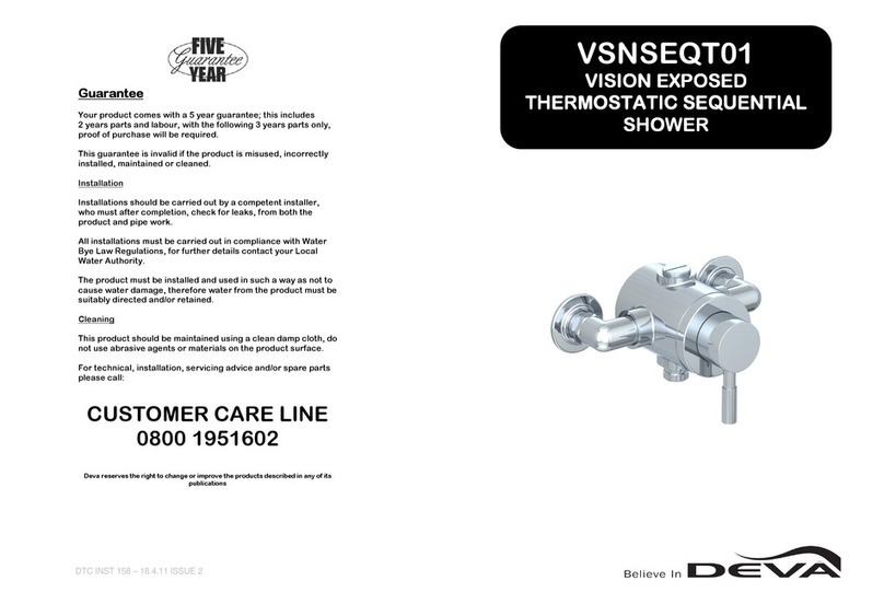
DEVA DLT TSM106 Instruction Manual

DTC INST 145 issue 2 – 16.11.07
Please retain this document for future use and
reference.
DLT TSM106
INSTALLATION AND MAINTENANCE
Guarantee
Your product comes with a 5 year guarantee; this includes
2 years parts and labour, with the following 3 years parts only, proof of
purchase will be required.
This guarantee is invalid if the product is misused, incorrectly installed,
maintained or cleaned.
Installation
Installations should be carried out by a competent installer, who must
after completion, check for leaks, from both the product and pipe work.
All installations must be carried out in compliance with Water Bye Law
Regulations, for further details contact your Local Water Authority.
The product must be installed and used in such a way as not to cause
water damage, therefore water from the product must be suitably
directed and/or retained.
Cleaning
This product should be maintained using a clean damp cloth, do not use
abrasive agents or materials on the product surface.
For technical, installation, servicing advice and/or spare parts please
call:
CUSTOMER CARE LINE
0800 1951602
Deva reserves the right to change or improve the products described in any of its
publications

DTC INST 145 issue 2 – 16.11.07
Operating Conditions of Use
Prior to installation the operating conditions of use must be checked. The table
shown (Table 1) contains details of the necessary conditions of operation.
NOTE: If your water system cannot meet these conditions then the valve cannot
be guaranteed to operate as a Type 2 valve. This valve is suitable for use
with Low Pressure (BSEN1287) operating conditions.
Please note valves must always be operated within the range for BS EN1287.
Operating pressures above 5 bar will require installation of a pressure reducing
valve (not supplied)
TABLE 1
(Valve designation of use for this product: LP Tub BS EN1287)
BS EN1287
MAXIMUM STATIC PRESSURE 10 BAR
FLOW PRESSURE 0.1 – 1 BAR
(Note; Minimum 0.2 bar required for this product to meet LP Tub application)
HOT SUPPLY (°C) 55-65
COLD SUPPLY (°C) MAX 25
MAX MIXED TEMP (°C) MAX 46
Note:
46°C is the maximum mixed water temperature from the bath tap. The
maximum temperature takes account of the allowable temperature
tolerances inherent in thermostatic mixing valves and temperature losses
in metal baths.
It is not a safe bathing temperature for adults or children.
The British Burns Association recommends 37 to 37.5°C as a comfortable
bathing temperature for children. In premises covered by the Care
Standards Act 2000, the maximum mixed water outlet temperature is 43°C
Temperature Adjustment
This should be carried out by a competent person and only when absolutely
necessary.
Turn the handle anti-clockwise to fully hot.
Turn on the tap handles to allow water flow from the spout, let this run for
1 minute.
Check the temperature using a thermometer, this should read 46 °c, if not leave
the temperature handle in the fully hot position and remove the central
temperature control cap, by using a thin blade screwdriver, push this through
the hole to the rear of the central handle and force off the cap, remove the
centre screw in the handle, you do not need to remove the handle,.
This will expose the cartridge adjustment grub screw, insert an allen key into the
hole of the handle and locate into the grub screw and turn anti-clockwise to
increase the temperature or clockwise to decrease.
Ensure that you do not exceed the 46 °c.
Then re-fit the components to the mixer.

DTC INST 145 issue 2 – 16.11.07
Operating Conditions of Use (CONTINUED)
The mixer is designed to allow a maximum pre-set temperature of 46°c in line
with the TMV2 approval.
The mixer works within the parameters set out within the requirements of TMV2
at low pressure and is guaranteed to have the anti-scald facility up to 46°c,
which is the maximum limit stated in the standard.
In cases were the mixer is fitted to high pressure systems or systems with
mixed pressures, it become necessary to fit flow restrictors (supplied) in the
following scheme:
You will receive a kit composed of;
Yellow valve / pink insert x 1 – this is a flow restrictor and check valve
Yellow valve / white insert x 2 – these are flow restrictors and check valves
Brass housings x 2 – these hold the above
White valves x 2 – these are check valves only
SYSTEM COLD INLET HOT INLET
GRAVITY BOTH SIDES CHECK VALVE CHECK VALVE
MAINS COLD/GRAVITY HOT PINK CHECK VALVE
UNVENTED BOTH SIDES WHITE WHITE
PUMPED BOTH SIDES CHECK VALVE CHECK VALVE
GAS INSTANTANEOUS HEATER WHITE WHITE
MAINS COLD/PUMPED HOT WHITE WHITE
GRAVITY COLD/PUMPED HOT CHECK VALVE WHITE
(PINK RATE – 15 L/MIN ------ WHITE RATE - 8 L/MIN)
Commissioning and Testing
It is a requirement that all TMV2 approved valves shall be verified
against the original set temperature results once a year. When
commissioning/testing is due the following performance checks shall
be carried out.
NOTE: The mixed water temperature at the terminal fitting must never exceed
46°c
After installation the product and the pipe work must be checked for water
tightness, to ensure no leaks are present.
Once this has been carried out a cold water failure test should be completed
to check the shut off is operating correctly.
If the product has been installed in compliance with the operating specification
indicated this should operate correctly.
The product should be tested thereafter at intervals agreed by the
contractor/installer, but should never exceed 12 months.
The testing will only require a standard thermometer with a scale of more than
65°c. The temperature sensitive element of the ther mometer should be fully
inserted into the water flow of the mixer.
Measure the mixed water temperature.
Carry out a cold water failure test by using the isolation valve to shut off the
cold supply.
Wait for 5 seconds if the water is still flowing check the water temperature is
below 46°c. The flow should stop or reduce to a tri ckle.
Open the cold water isolation valve and measure the mixed water
temperature
If there is no significant change from the original settings and the shut off is
functioning correctly, no further action is required.
If the outlet temperature has drifted by more then 2°c, or the shut off does not
work correctly, a full service or re-commissioning is required.

DTC INST 145 issue 2 – 16.11.07
Valve Installation Criteria
The mixer must be installed in accordance with the following installation
guide.
The mixer has been supplied with filters which must be fitted, see section
“Product Installation”
The mixer is supplied with check valves which must be fitted, so that the
product is protected against cross flow due to unbalanced water pressures
as required by the Water Supply Regulations 1999.
Hot supply to be on the left and cold supply to be on the right.
The mixer must be installed in such a position that maintenance of the TMV
and its valves and the commissioning and testing of the TMV can be
undertaken.
The fitting of isolation valves (not included) is required as close as is
practicable to the water supply inlets of the mixer
The mixed water temperature from the terminal fitting should never exceed
46°c
Mixer Installation
Before installation flush the system thoroughly to remove any debris as this
will affect the performance of the product.
Once flushed turn off the water supply either at the stopcock or at the
isolation valves.
Place the gasket washer onto the top surface of the bath in line with the
bath holes.
Then place the mixer onto the bath with the cold feed on the right and hot
feed on the left.
Push the mixer tail through the bath holes.
From the underside, push on back nut washer and push to underside of
bath, then connect the back nuts and screw up to underside of bath and
tighten to secure mixer (do not over tighten as this may damage the bath)
Then connect the water supplies to the mixer tails, ensuring to use an
adequate sealing method.
Check that the mixer is in bath fill mode and turn on water supply and check
for leaks.
Finally secure the wall bracket to the wall using the screw provided,
ensuring that hose is not under tension when fitted to the wall bracket and
mixer.
Connect the hose to the handset using the coned end and fit washer, then
connect opposite end to mixer outlet again fitting washer.

DTC INST 145 issue 2 – 16.11.07
Installation of Check Valves and Restrictors
Before installation you must determine whether or not the flow restrictors
supplied are required.
The white restrictors x 2 will be fitted to the brass housings, the pink
restrictor x 1 will be separate.
Please note that the flow restrictors also include built in check valves and
therefore the large white plastic checks valves would not be required if
flow restrictors are fitted to both sides, if no flow restrictors are fitted
ensure to fit the check valves.
To change the flow restrictors, simply push out the restrictor (1) which is
fitted to the brass housing (2), then push in fully the required restrictor,
ensuring that the restrictor is uppermost with the check valve at the
bottom as shown.(O ring at the bottom)
To install the check valve/flow restrictor or check valve to the mixer, push
the components into the mixer tail as far as it will insert, with ‘o ring to the
bottom.
Then push in the filter disc to the underside of the check valve, followed
by the retaining clip, ensure that this clip sits inside the groove on the
inside of the tail.
Product Operation
To operate the mixer in bath mode ensure that diverter is in the up position,
then open both handles to allow water flow into the bath from the spout, to
control the temperature only turn the central temperature control, to control
the flow turn the outside handles.
To operate the shower mode turn on the mixer by opening the outside
handles allow water to flow, then push down on the diverter located beneath
the hose, this will allow water to flow form the handset, control temperature
and flow as stated above.
Under normal use at 0.2 bar and above, when the mixer is turned off the
diverter will automatically return to bath mode, so the next time the mixer is
used the product will be in bath mode not shower.
At pressure of below 0.2 bar, the manual override may be required, to
operate this, push down on the diverter and turn, this will lock the diverter
into position.
NOTE, WHEN USING THE MANUAL OVERRIDE IT IS RECOMMENDED
TO DIVERT BACK TO BATH MODE AFTER USE TO PREVENT WATER
DISCHARGE ON THE BATHER WHEN NEXT USED.
Table of contents
Other DEVA Bathroom Fixture manuals
Popular Bathroom Fixture manuals by other brands

Zline
Zline BLISS Series Installation and user manual
HAFA
HAFA IglooPro R manual
Hans Grohe
Hans Grohe Raindance Select Showerpipe EcoSmart 240 Instructions for use/assembly instructions

BEMMA
BEMMA TERRA VT-TR48 instructions

WESTBRASS
WESTBRASS WAS00X-07 quick start guide
Vicenza Designs
Vicenza Designs TP9000S Instructions for installation

Kohler
Kohler K-419 installation guide
Glacier bay
Glacier bay HD873X-4501 Installation and care guide

Kohler
Kohler K-8247 Homeowner's guide
Akw
Akw TF75 Installation and user care instructions

KRHÜNER
KRHÜNER 36608 instruction manual
rba
rba Raffaello RBA4601 Series Installation, operation and maintenance instructions
