Develco ZHOT101 User manual

1
Technical Manual for
ZHOT101 - ZigBee Occupancy, Temperature &
Light Sensor

2
Copyright © Develco Products A/S
All rights reserved.
Develco Products assumes no responsibility for any errors, which may appear in this manual.
Furthermore, Develco Products reserves the right to alter the hardware, software, and/or
specifications detailed herein at any time without notice, and Develco Products does not make any
commitment to update the information contained herein.
All the trademarks listed herein are owned by their respective owners.
RoHS

3
Contents
1Cautionary Notes ................................................................................ 4
2Features ............................................................................................ 5
2.1 ZHOT101 - ZigBee Occupancy, Temperature & Light Sensor......................... 5
2.2 Key features..................................................................................... 5
3Endpoints........................................................................................... 6
3.1 ZigBee Device Object (ZDO) .............................................................. 6
3.2 Occupancy Sensor ............................................................................ 6
3.3 Temperatur Sensor ........................................................................... 6
3.4 Light Sensor..................................................................................... 6
3.5 Develco Utility.................................................................................. 6
4Supported Clusters.............................................................................. 7
4.1 Common clusters for each end point ................................................... 7
4.2 Occupancy Sensor Device – EP 0x22, EP 0x28 and 0x29........................ 8
4.3 Temperature Sensor Device – EP 0x26 ...............................................11
4.4 Light Sensor Device – EP 0x27 ..........................................................12
5MMI user guide..................................................................................13
5.1 Push Button Menu: ..........................................................................13
5.2 Action upon Push Button Release.......................................................13
5.3 Action on Power On..........................................................................14
5.4 Join Device on a Network..................................................................14
5.5 Toggle Identify Mode........................................................................14
6General network behaviour .................................................................15
6.1 Installation......................................................................................15
6.2 Normal – Keep alive.........................................................................
15
6.3 Low battery.....................................................................................16
7ZigBee Home Automation Commissioning .............................................17
8Specifications ....................................................................................18
8.1 Common.........................................................................................18
8.2 Occupancy:.....................................................................................18
8.3 Light:.............................................................................................18
8.4 Temperature:..................................................................................18
9Contact Information ...........................................................................19
10 About Develco Products A/S................................................................20

4
1Cautionary Notes
Develco Products A/S reserves the right to make changes to any product to improve reliability without
further notice. Develco Products A/S does not assume any liability arising out of the application or use
of any product or circuit described herein; neither does it convey any license under patent rights or
the rights of third parties.

5
2Features
2.1 ZHOT101 - ZigBee Occupancy, Temperature & Light Sensor
The multi sensor enables you to detect movement and light as well as measuring temperature.
The sensor is battery powered and can be mounted in four different ways: flat on the wall, flat on the
ceiling, in the corner (using a 45° bracket), or standing (on a shelf, table, or similar).
The sensor has 3 ZigBee end points, one for each sensor. The Occupancy end point contains 2 logic
modules that combines’ Occupancy with temperature and light sensor. Each end point can be used
separately. Standard ZigBee ZCL “Configure Reporting” on change and on time is supported.
2.1.1 Occupancy
The occupancy sensor is PIR based, sensing moving objects up to 6 meters from the sensor. The off-
time is adjustable remotely via ZigBee. The end point is configured as Home Automation profile
„Occupancy Sensor“.
2.1.2 Light
The light sensor is a low-accuracy sensor reporting light level. The end point is configured as Home
Automation profile „Light Sensor“.
2.1.3 Temperature
The temperature sensor measures temperature with a resolution of 0.1°C. The end point is configured
as the Home Automation profile „Temperature Sensor“.
2.2 Key features
Key features are:
•Temperature sensor
•Occupancy sensor
•Light sensor
•Certified ZigBee Home Automation application profile
•ZigBee PRO is supported
•Communication based on DevCom07 ZigBee Module.
•RoHS compliant according to the EU Directive 2002/95/EC.
•Standard ZigBee Home Automation security and stack settings are used.

6
3Endpoints
The device implements the following standard HA devices on different end points.
3.1 ZigBee Device Object (ZDO)
•End point number 0x00
•Application profile Id 0x0000
•Application device Id 0x0000
•Supports all mandatory clusters
3.2 Occupancy Sensor
•End point number 0x22, 0x28 and 0x29
•Application profile Id 0x0104 (Home Automation)
•Application device Id 0x0107
Each end point contains a logic module that can be configured to control the occupancy sensor signal
base on the user defined settings for the temperature sensor input or the user defined settings for the
light sensor input.
3.3 Temperatur Sensor
•End point number 0x26
•Application profile Id 0x0104 (Home Automation)
•Application device Id 0x0302
3.4 Light Sensor
•End point number 0x27
•Application profile Id 0x0104 (Home Automation)
•Application device Id 0x0106
3.5 Develco Utility
•Application profile Id 0xC0C9 (Develco Products private profile)
•Application device Id 0x0001
•Private profile for internal Develco Products use only.
The DevUtil end point support a Develco products specified bootloader.
New firmware can be downloaded to the device using the SmartAMM server + SmartAMM client tool.
REFERENCE DOCUMENTS
053474r18ZB_CSG-ZigBee-Specification.pdf
075123r03ZB_AFG-ZigBee_Cluster_Library_Specification.pdf
053520r27ZB_HA_PTG-Home-Automation-Profile.pdf
075356r15ZB_ZSE-ZSE-AMI_Profile_Specification.pdf
They can all be downloaded from :
http://www.zigbee.org/Products/DownloadZigBeeTechnicalDocuments.aspx

7
4Supported Clusters
4.1 Common clusters for each end point
The ZCL “General Function Domain” clusters in this section are implemented as server clusters. Refer
to ZigBee Cluster Library Specification. http://www.zigbee.org/Specifications.aspx
4.1.1 Basic – Cluster id 0x0000
Only the first set has mandatory attributes, also the optional attributes that can be relevant to a
Develco device are all in set 0x000
4.1.1.1 Attribute
Id# Name type range Man
/Opt
Relevance and ref.
0x0
ZCLVersion
Uint8
Type range
M
0x4
ManufacturerName
String
0-32 byte
O
4.1.1.1.1
0x5
ModelIdentifier
String
0-32 byte
O
4.1.1.1.2
0x7 PowerSource 8 bit
enum
Type range M
4.1.1.1.1 ManufacturerName
“Develco Products A/S”
4.1.1.1.2 ModelIdentifier
“ZHOT101 - ZigBee Occupancy, Temperature & Light Sensor”
4.1.2 Identify – Cluster id 0x0003
4.1.2.1 Attribute
Id#
Name
type
range
Man
/Opt
Relevance and ref.
0x0000
IdentifyTime
Uint16
Type range
M
4.1.2.2 Commands
The identify cluster has 2 commands as server.
Id# Name Payload Man
/Opt
Relevance and ref.
0x00
Identify
Uint16 - Identify Time (seconds)
M
0x01
Identify Query
none
M
The identify cluster has 1 command as client.
Id# Name Payload Man
/Opt
Relevance and ref.
0x00 Identify Query
Response Uint16 - Identify Time (seconds) M
4.1.3 Power Configuration - Cluster id 0x0001
The power configuration cluster is described in ZigBee Cluster Library Specification section 4.8
4.1.3.1 Attribute
Id#
Name
type
range
Man
/Opt
Relevance and ref.
0x0020
BatteryVoltage
Uint8
0x00 - 0xFF
O

8
4.2 Occupancy Sensor Device – EP 0x22, EP 0x28 and 0x29
Each end point contains a logic module that can be configured to control the occupancy sensor signal
base on the user defined settings for the temperature sensor input or the user defined settings for the
light sensor input.
The manufacture specific attributes in section 4.2.1.2 is used to configure the logic module.
The ZCL “Measurement and Sensing” cluster in this section is implemented as a server cluster. Refer
to ZigBee Cluster Library Specification.
4.2.1 Occupancy sensing - Cluster id 0x0406
The occupancy sensing cluster is described in ZigBee Cluster Library Specification section 4.8
4.2.1.1 Attribute
Id# Name type range Man
/Opt
Relevance and ref.
0x0000
Occupancy
8-bit Bitmap
0000000x
M
Reporting is supported
0x0001 Occupancy Sensor Type
8-bit
Enumeration
0x00 – 0xfe M Hard coded to PIR
sensor
0x0010
PIROccupiedTo
UnoccupiedDelay
Uint16
Type range O The time delay, in
seconds, before the PIR
sensor changes to its
unoccupied.
0x0011
PIRUnoccupiedTo
OccupiedDelay
Uint16
Type range O The time delay, in
seconds, before the PIR
sensor changes to its
occupied
0x0012
PIRUnoccupiedTo
OccupiedThreshold
Uint8
Type range O
Specifies the number of
movement detection
events that must occur
before the PIR sensor
changes to its occupied
state.
Note: Default value for PIR occupied to unoccupied is 4 minutes
4.2.1.2 Manufacture Specific Attribute
Id# Name type range Man
/Opt
Relevance and ref.
0xFC00 ArmThreshold_
MinTemperature
Sint16 0x954d –
0x7ffe
M Write/read is supported
0xFC01 ArmThreshold_
MaxTemperature
Sint16 0x954d –
0x7ffe
M Write/read is supported
0xFC02 TargetLevel Uint16 0x0002 –
0xfffd
M Write/read is supported

9
4.2.2 Occupancy Sensor using temperature sensor input
End point 0x22, 0x28 and 0x29 can be configured as a logic module that controls the occupancy
sensor signal base on the user defined settings for the temperature sensor input.
Logic module
If
(Temperature > ArmThreshold_MaxTemperature )
or
(Temperature < ArmThreshold_MinTemperature )
Temperature measure value
Cluster ID 0x0402
Attribute ID 0x0000 Occupancy state
Occupancy state
Use case – Energy savings in an office building
The device is installed to obtain energy savings in an office with an air condition. A ZigBee relay is
installed to turn on the air condition when the occupancy sensor detects movements in the room. This
functionality can be obtained by using the standard occupancy sensor functionality – Standard ZCL
attributes.
Using the manufacture specific attributes in section 4.2.1.2 provide the user with an extra check
before the air condition is turned on.
The installer can configure the ArmThreshold_MaxTemperature attribute to 25 degrees and when
movements are detected in the room the relay only turns on the air condition when the temperature is
above the MaxTemperature Setting (25 degrees).
The ArmThreshold_MinTemperature attribute can be used in winter season where the air condition
shall warm up the room. The MinTemperature attribute is configured to 20 degrees and when
movements are detected in the room and the temperature is below MinTemperature the air condition
is turned on heating the room.
20 degrees
MinTemperature 25 degrees
MaxTemperature
Air Condition
OFF
Air Condition
ON
Cooling
Air Condition
ON
Heating
Temperature
10
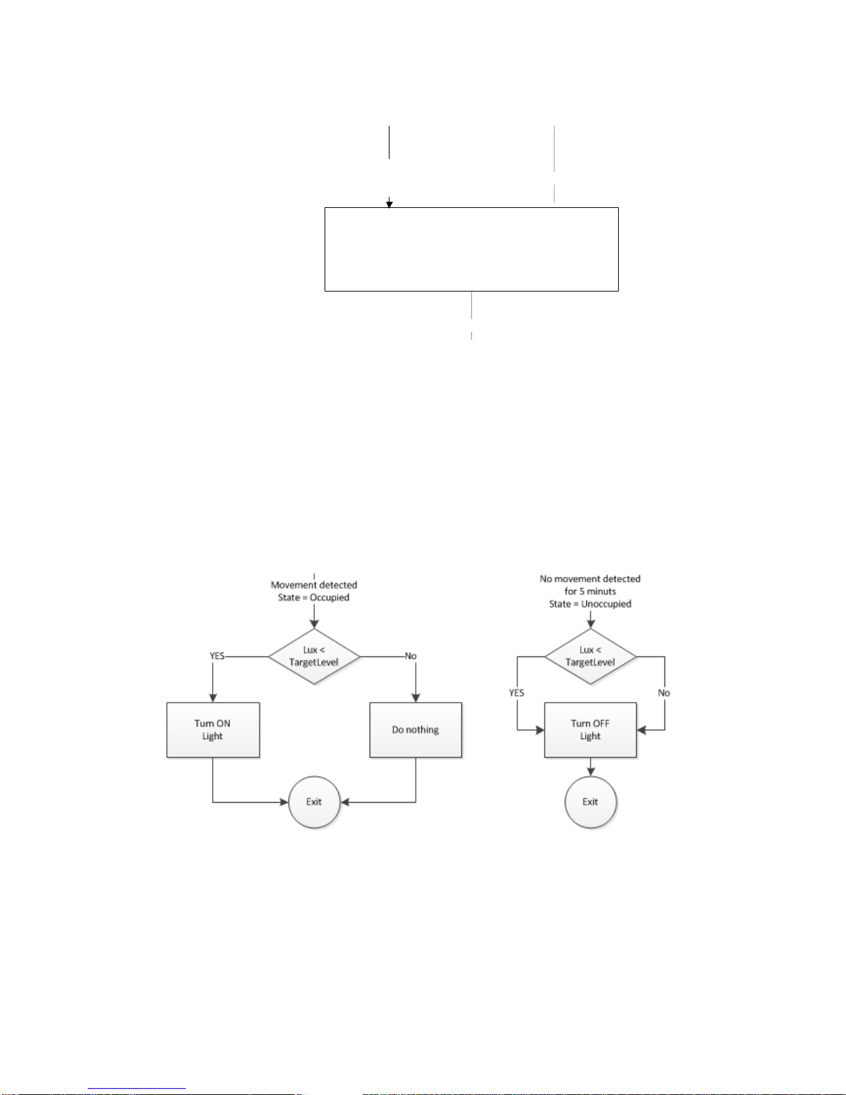
4.2.3 Occupancy Sensor using illumination sensor input
End point 0x22, 0x28 and 0x29 can be configured as a logic module that controls the occupancy
sensor signal base on the user defined settings for the illumination sensor input.
Logic module
If Illumination is
X < TargetLevel
Illuminance measure value
Cluster ID 0x0400
Attribute ID 0x0000 Occupancy state
Occupancy state
Use case – Energy savings in an office building
The device is installed to obtain energy savings in an office controlling the light. A ZigBee relay is
installed to turn on the light when the occupancy sensor detects movements in the room. This
functionality can be obtained by using the standard occupancy sensor Standard functionality - ZCL
attributes.
Using the manufacture specific attributes in section 4.2.1.2 provide the user with an extra check
before the air light is turned on.
The installer can configure the TargetLevel attribute to a user defined Lux level. When movements are
detected in the room and the Lux level is below the TargetLevel the relay turns on the light.

11
4.2.4 Binary Input Basic - Cluster id 0x000F
Each occupancy sensor end points support a binary input basic cluster with is used for tamper
indication and acknowledge of the tamper. The basic cluster is mapped to the same internal values for
each end point.
The binary input basic cluster is described in ZigBee Cluster Library Specification section 3.14.4
4.2.4.1 Attributes
Id#
Name
type
Range
Man
/Opt
Relevance and ref.
0x0051
OutOfService
Boolean
True/False
M
0x0055
PresentValue
Boolean
True/False
M
0x006F StatusFlags 8-bitmap 0x00 –
0xff
M
4.2.4.1.1 OutOfService
When a tamper event is send the OutOfService attribute is set to TRUE. The back end system has to
send an acknowledged to clear the current tamper event. When the OutOfService attribute is set to
FALSE the tamper event is stopped.
4.2.4.1.2 PressentValue
This attribute is reported when a tamper event is trigger (On state changes). The attribute is sent
every 2 minute until the OutOfService attribute is set to FALSE.
Note: A ZCL binding has to be established before the tamper event can be send.
4.3 Temperature Sensor Device – EP 0x26
The ZCL “Measurement and Sensing” cluster in this section is implemented as a server cluster. Refer
to ZigBee Cluster Library Specification.
4.3.1 Temperature Measurement – Cluster id 0x0402
The temperature measurement cluster is described in ZigBee Cluster Library Specification section 4.4
4.3.1.1 Attribute
Id# Name type Range Man
/Opt
Relevance and ref.
0x0000 MeasuredValue Sint16 MinValue to
MaxValue
M ZCL Reporting is hard
coded to every 2 minutes
0x0001 MinMeasuredValue Sint16 0x954d –
0x7ffe
M
0x0002 MaxMeasuredValue Sint16 0x954d –
0x7ffe
M
4.3.1.1.1 MinMeasuredValue
The temperature sensor is NOT supporting temperature measurements below 0 degrees Celsius
4.3.1.1.2 MaxMeasuredValue
The temperature sensor is NOT supporting temperature measurements above 50 degrees Celsius

12
4.4 Light Sensor Device – EP 0x27
The ZCL “Measurement and Sensing” cluster in this section is implemented as a server cluster. Refer
to ZigBee Cluster Library Specification.
4.4.1 Illuminance Measurement - Cluster id 0x0400
The illuminance measurement cluster is described in ZigBee Cluster Library Specification section 4.2
4.4.1.1 Attribute
Id#
Name
type
range
Man
/Opt
Relevance and ref.
0x0000 MeasuredValue Uint16 MinValue to
MaxValue
M ZCL Reporting is hard
coded to every 2 minutes
0x0001 MinMeasuredValue Uint16 0x0002 –
0xfffd
M
0x0002 MaxMeasuredValue Uint16 0x0001 –
0xfffe
M
0x0004 LightSensorType 8-bit
Enumeration
0x00 – 0xff O
4.4.1.1.1 MinMeasuredValue
The minimum Lux value supported by the device is 3 Lux. Converting 3 Lux into min measured value:
=10000*LOG(3)+1 = 4772
Min measured value in Hex = 0x1274
4.4.1.1.2 MaxMeasuredValue
The maximum Lux value supported by the device is 70.000 Lux. Converting 70.000 Lux into max
measured value: =10000*LOG(70000)+1 = 48452
Max measured value in Hex = 0xBD43
13
5MMI user guide
5.1 Push Button Menu:
Pushing the button on a device provides the user with several possibilities.
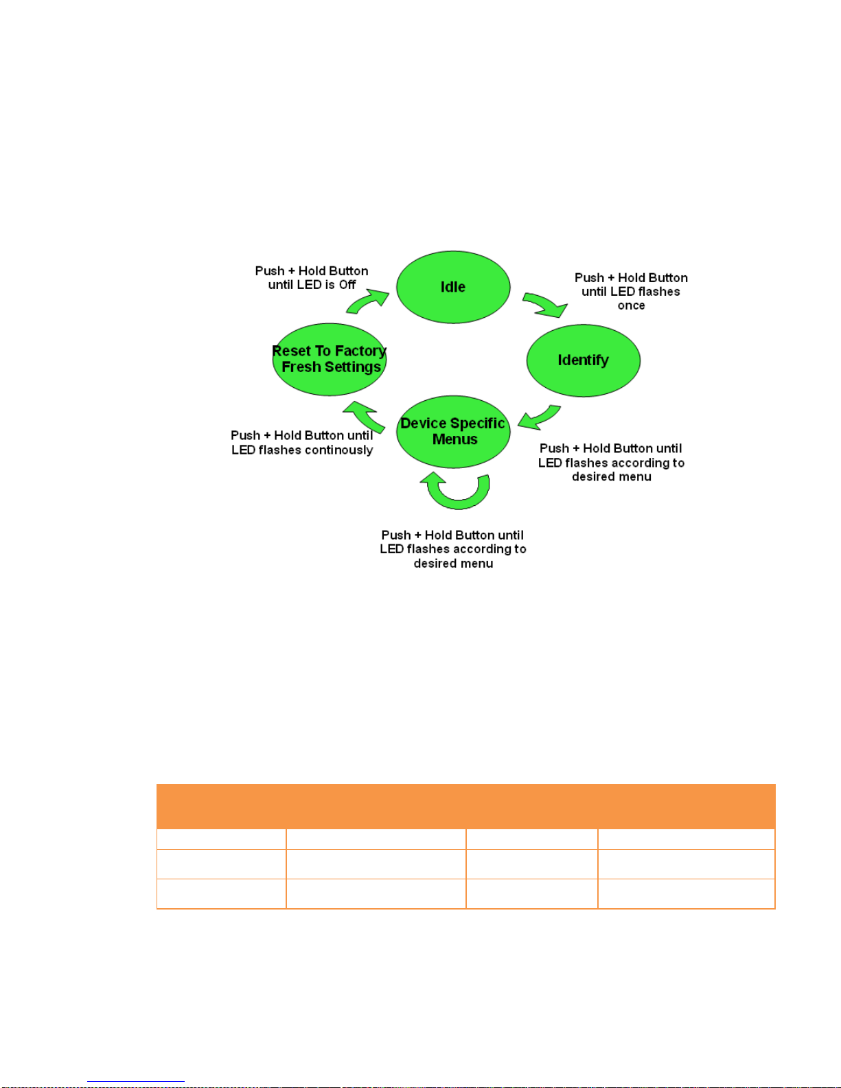
A single short push has a specific meaning for the given device, for this sensor a single short push will
toggle the occupancy status (occupied/unoccupied.). Pushing the button for longer (push, hold for a
few seconds, and release) allows the user to set the device into a desired mode. A mode change
happens at 5 second interval. Below, these modes are illustrated in a state chart.
When cycling through the menu modes, the state is indicated by a number of 100ms blinks on the
LED. As illustrated in the figure, the menu system allows for device specific modes (e.g. Pair Devices
for Devices such as relays and occupancy sensors).
5.2 Action upon Push Button Release
The number of blinks associated with a given mode entry is shown in the below table along with the
associated action performed upon user button release. As indicated, if the user holds the button past
the Reset to Factory Fresh Settings no action will result from the push button and the device stays in
the idle state.
Mode
Number of flashes on mode
menu entry
Availability
Action Taken upon Button
Release
Idle
None
All devices
None
Identify
1
All devices
Toggle Identify Mode
(On/Off)
Reset To Factory
Fresh Settings
Continuous flash (>8)
All Devices
Reset device to factory
fresh settings

14
5.3 Action on Power On
As a general rule, all end devices and routers that have not previously joined a network (or have been
reset to factory default) will start up and search for a coordinator on the channels enabled for that
device. In this mode, the LED will flash once every second.
Once a device has joined a network, the device will be in Identify Mode for 15 minutes indicated by a
flash of the LED once every three seconds.
If a device has joined a network and is powered down, it will attempt to rejoin this network upon
power up. For the first 30 seconds hereafter, the device will be in Identify Mode.
5.4 Join Device on a Network
To allow a device to join a network, one either has to power up a device that has not previously joined
a network or push the button until the Reset To Factory default mode is indicated – and subsequently
release the button. This will cause the device to reset to its factory default state and scan for a
suitable coordinator.
5.5 Toggle Identify Mode
To enter Identify Mode, the user may push and hold the button until the Identify Mode menu is
indicated. If the device was not already in Identify Mode, the mode will be entered. Vice versa, if the
device was already in Identify Mode, the mode will be disabled by the same action.
15
6General network behaviour
6.1 Installation
When the device is virgin and powered for the first time it will start looking for a ZigBee PAN
Coordinator or router to join. The device will scan each ZigBee channel starting from 11 to 24. The
LED will flash once every second until it joins a device.
#Scan mode - 1
Scan all 16
ZigBee channel
until join network
or 15 minutes
#Sleep mode
MCU is in sleep
mode (Radio off)
15 minutes
#Scan mode - 2
Scan all 16
ZigBee ch x 4 or
until join network
~ 2 minutes
#Sleep mode
MCU is in sleep
mode (Radio off)
15 minutes
#Scan mode - 2
Scan all 16
ZigBee ch x 4 or
until join network
~ 2 minutes
The device will start up using scan mode 1. To increase battery lifetime when the device is joining a
network for the first time a scan mode 2 will be used after scan mode 1 has expired. Scan mode 1 it
will only be executed one time when the devise is powered.
In section 5 “MMI” it is explained how to put the device into a join or leave network mode.
Network settings are stored in NV-memory are after a power cycle the device re-join the same
network.
If the device has to join a new PAN coordinator the MMI menu supports a “Reset To Factory Fresh
Settings” mode. This will erase all current network information.
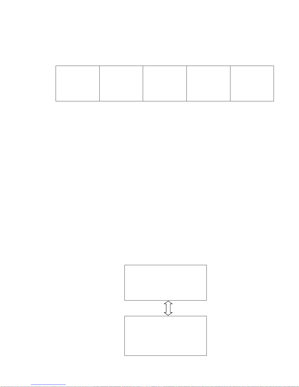
6.2 Normal – Keep alive
The device is sending a “keep alive” message to the PAN coordinator every 15 minute to verify that
the device is still connected to the network.
6.2.1 Network lost
If no “keep alive” responses are received 5 times in a row (Worst case 1h15m), the devices will start
scanning every ZigBee channel for the PAN coordinator and try to re-join it. After scanning all 16
channels 4 times in a row the device will enter sleep mode. The device will toggle between each mode
until a re-join occur.
When the device is in scan mode the LED will flash once every second until it re-joins the network.
According to the ZigBee specification TX is NOT allowed to be enabled all the time and a TX silent
period has to be defined.
#Scan Mode
Scan all 16 ZigBee channel x 4
~ 2 minutes
LED is flashing once every 1 sec
#Sleep mode
MCU is in sleep mode (Radio off)
15 minutes
LED = OFF

16
6.3 Low battery
The current battery voltage can be read from the power configuration cluster described in section
4.3.1. The attribute “BatteryVoltage” is measuring the battery voltage, in units of 100mV.
There is no led indication for low battery on the PIR sensor itself.

17
7ZigBee Home Automation Commissioning
ZigBee Home Automation specifies a common language which all ZigBee Home Automation devices
must use to document commissioning of the device.
Below is a table outlining the Develco ZigBee HA device MMI using this common language.
ZigBee Action
Availability
What To Do To Device To Perform Action
Join Network Routers and End Devices Press and hold button until Reset To Factory
Fresh Settings menu is reached (continuous
flash of LED) and then release button.
Form Network
-
Not Supported
Allow Others To Join
Network
- Not Supported
Restore Factory Fresh
Settings All devices Press and hold button until Reset To Factory
Fresh Settings menu is reached (continuous
flash of LED) and then release button.
Pair Devices
Routers and End Devices
Press and hold button until Pair Devices menu
is reached (LED flashes twice) and then
release button.
Enable/Disable Identify
Mode
All devices
Press and hold button until Enable Identify
Mode menu is reached (LED flashes once) and
then release button.
Create Scene
-
Not Supported

18
8Specifications
8.1 Common
• Dimensions: 106 x 61 x 54 mm
• Colour: White
• Battery: CR123, exchangeable
• Battery life: up to 5 years, hourly reporting
• Operation temperature: 0 to +50°C
• Sensitivity: -94 dBm
• Output power: +3 dBm
• Alive telegram using ZigBee ZDP “IEEE_addr_req” messages
8.2 Occupancy:
• Range: 6m
• View angle: 45° up/down, left/right
• Off-time: configurable 2 s - 65,000 s
8.3 Light:
• Resolution: 3 to 70.000 Lux
Common light source illuminance (lux) table
Street Light 20
Dusk 1 to 100
Living Room 50 to 200
Office 200 to 600
Operating Room 5 k to 10 k
Cloudy 2 k to 10 k
hazy 25 k to 50 k
Bright Sun 50 k to 100
• Tolerance: < 10,000 lux: ± 5% of the measurement and ± 5 Lux.
> 10,000 lux: ± 10% of the measurement and ± 5 Lux.
• Reporting: configurable
8.4 Temperature:
• Range: 0 to +50°C
• Resolution: 0.1°C
• Accuracy: Typically ±0.5°C and Max ±1°C
• Reporting: configurable

19
9Contact Information
Technical support: Please contact Develco Products for support.
products@develcoproducts.com
Sales: Please contact Develco Products for information on prices, availability,
and lead time.
info@develcoproducts.com

20
10 About Develco Products A/S
Energy efficiency, Savings & Comfort
Develco Products provides communication systems for AMR, AMI and Smart Metering. Develco
Products presents a complete solution facilitating the remote control of appliances via intelligent
electricity meters or gateways also capable of communicating with other meters.
SmartAMM
SmartAMM is a modular concept securing a flexible and forward-looking Smart House solution.
SmartAMM makes it possible to monitor and control your home’s electrical appliances and energy
consumption via smart meters. SmartAMM combines automated meter reading with home automation,
and includes:
•AMR (Automated Meter Management) for existing metering solutions
•AMR for meter manufacturers
•Communication modules for integration in meters or appliances (ZigBee, Z-Wave, PLC, GPRS,
GSM and others)
•Data concentrators with back-office communication (GPRS, SMS, Internet, Fiber, PLC)
•Home Automation
BENEFITS
•Cheap and reliable metering
•Reduced energy consumption
•Optimized energy consumption (peak level out)
•Avoidance of blackouts
•Sale of extra services:
oReadout of several meters by diverse manufacturers and types (water, heating, gas,
electricity)
oSurveillance
oAlarms
Selected cases
•DONG Energy Gas (AMR of gas meters via GPRS data concentrator)
•Dong Energy Power (control and alarm via SmartRead power meter)
•EnergiMidt (SmartAMM concept covering metering (water & heating) and energy display via
power meters as well as home automation.
Everything integrated into one module and installed in the Echelon PLC power meter).
Table of contents
Other Develco Accessories manuals

Popular Accessories manuals by other brands

Honeywell
Honeywell NOTIFIER SMART 2 NFX-SMT2 Installation and maintenance instructions

Monacor
Monacor JTS MA-HPF operating instructions

VOLTCRAFT
VOLTCRAFT PB-17C operating instructions

Masimo
Masimo RD SET manual

Echo
Echo 99944100025 instructions

Vertiv
Vertiv GEIST SwitchAir SA2-003 Quick installation guide


