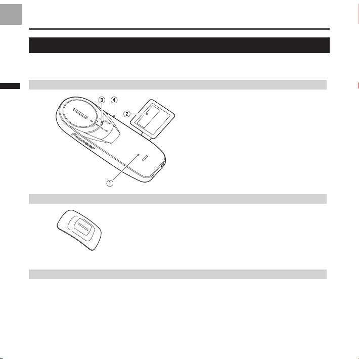
Pioneer SGY-PM930H User manual

EN
DE
FR
NE
IT
ES
EN
DE
FR
NL
IT
ES
JP
Please read the "Important Information for the User" in the product box
for product warnings and other important safety information.
User's Manual
Pedaling Monitor Sensor
SGY-PM930H
SGY-PM930HL
SGY-PM930HR
取扱説明書

2
EN
Introduction
Table of Contents
Introduction
Features..................................................................................... 4
Compatibility .............................................................................. 7
Getting Started
Product Conguration................................................................ 8
Installing and Removing the Batteries......................................13
Switching to the pedaling monitor mode..................................16
Switch to dual power meter mode............................................... 20
Switch to single power meter mode ........................................ 24
Pairing /Calibration
Pairing with the Cyclocomputer............................................... 25
Calibrating the sensors (zero point calibration)....................... 27
Specifications and support
Troubleshooting ....................................................................... 29
Specications .......................................................................... 32
Care, Maintenance, and Storage ............................................ 33
Introduction

3
EN
Introduction
This product is ANT+™ certied.
Visit http://www.thisisant.com/directory/
for a list of compatible products and apps.
The
Bluetooth
®word mark and logos are registered
trademarks owned by Bluetooth SIG, Inc. and any
use of such marks by PIONEER CORPORATION
is under license. Other trademarks and trade
names are those of their respective owners.

4
EN Features
This product is a sensor system that analyzes the pedaling of a bicycle in real
time. It calculates the direction and intensity of the force acting on the pedals
and calculates pedaling efciency.
Description of components
• Strain gauge unit :
Detects the strain on the crank and calculates the direction and intensity of the
force on the crank.
• Magnet:
Used to detect the angle of rotation.
• Transmitters:
Send information from the strain gauge unit and the magnet to the
Cyclocomputer.
Product mode
• When using SGX-CA600, the rmware version is required to be the latest version.
• Pedaling monitor mode:
When paired with Cyclocomputer SGX-CA600, the pedaling efciency and
cadence and other such properties can be measured. You can make maximum
use of the functions of this product.
• Dual power meter mode:
Left and right sensors are required. The actual power values of the left and right
sensors can be totaled and displayed and the cadence can be measured. Can be
used with SGX-CA600 or with a Cyclocomputer that supports ANT+ from another
manufacturer.
• Single power meter mode:
The power value of the left or right sensors can be doubled and displayed quickly
and the cadence can be measured. Can be used with SGX-CA600 or with a
Cyclocomputer that supports ANT+ from another manufacturer.

5
EN
Introduction
Switching modes
• When using SGX-CA600, the rmware version is required to be the latest version.
• Pedaling monitor mode (Page 16)
Can be switched with SGX-CA600. Cannot be switched with cyclocomputers from
other manufacturers. When the mode is switched to pedaling mode, the LEDs on the
sensors light green for 10 seconds.
Current mode Method 1
(Right sensor push switch)
Method 2
(SGX-CA600)
LED
lighting
method
Dual power meter Cannot be switched ○The LEDs light
green for 10
seconds
Single power meter Cannot be switched ○
• Dual power meter mode (Page 20)
The mode can be switched on SGX-CA600 or by operating the right sensor push
switch. When using with another manufacturer’s Cyclocomputer, switch using
method 1. When the mode is switched to powermeter mode, the LEDs light orange
for 10 seconds.
Current mode Method 1
(Right sensor push switch)
Method 2
(SGX-CA600)
LED
lighting
method
Pedaling monitor Cannot be switched ○The LEDs light
orange for 10
seconds
Single power meter ○ ○

6
EN
Introduction
• Single power meter mode (Page 24)
SGX-CA600 is required to switch from pedaling monitor mode. Cannot be switched
with cyclocomputers from other manufacturers. To switch from the dual power meter
mode, use SGX-CA600 or press the push switch of the right sensor. When the mode
is switched, the LEDs on the sensors blink orange for 10 seconds.
Current mode Method 1
(Right sensor push switch)
Method 2
(SGX-CA600)
LED
lighting
method
Pedaling monitor Cannot be switched ○The LEDs blink
orange for 10
seconds
Dual power meter ○ ○
Manuals
The product’s manuals consist of this User’s Manual, Support Pages, and
Important Information for the User.
• User’s Manual (this document)
Explains how to switch the modes of the product, and how to pair the product
with the Cyclocomputer and calibrate the sensors.
• Support pages (WEB site)
http://pioneer-cyclesports.com/us-en/support/products/
Explains details about handling methods. How to detach the product (for
dealers) is also described in the references.
• Important Information for the User
Important Information for the User provides detailed information related to
safety.

7
EN
Introduction
Compatibility
Crank set
This product supports the following crank sets.
Crank set Remarks
SHIMANO FC-R9100
Supports 165 / 167.5 / 170 / 172.5 / 175 / 177.5 / 180 mm crank length,
and 50-34T / 52-36T / 53-39T / 54-42T / 55-42T crank sets.
*
SHIMANO FC-R8000
Supports 165 / 170 / 172.5 / 175 mm crank length and 50-34T / 52-36T /
53-39T crank sets.
*
* This manual explains the crank set of 170 mm length with examples.
• When replacing the chain ring, be careful not to disconnect the junction cable of the right
pedaling monitor sensor. See the video on how to remove the chain ring rst on
http://pioneer-cyclesports.com/us-en/support/products/ to conrm the procedure.
Special skills and tools are needed for the installation and calibration of the
product. To install and calibrate, always ask the shop from where you bought the
product to do it.
Since the product is attached to the crank set with an adhesive, it cannot be
removed without destroying the sensor.

8
EN
Getting Started
SGY-PM930H
This product contains the following parts.
Pedaling monitor sensor (left side)
Pedaling monitor sensor (right side)
Product Conguration
①Left transmitter
②Strain gauge unit
③LED
④Device Number
(Described on the back)
Pedaling monitor sensor part (left side)
①Right transmitter
②Junction cable
③Strain gauge unit
④Junction box
⑤Device Number
(Described on the back)
Pedaling monitor sensor part (right side)

9
EN
Getting Started
Product Conguration
Magnet
Patch type x 2
Others
• User’s Manual (this document)
• Warranty Card
• Batteries (CR2032) x 2 (preinstalled in the sensors)
• Hex screws (M2.6 x 8 mm) x 3 (for the right transmitter x 3)
• Hex screws (M2.6 x 5 mm) x 3 (spare for the right transmitter cover x 3)
• Patch type magnet base × 2
• Tape for installing the chain ring adapter
For FC-R9100 Chain ring Adapter
For FC-R8000
Strain gauge unit cover x 1
for each type

10
EN
Getting Started
Product Conguration
SGY-PM930HL
This product contains the following parts.
Pedaling monitor sensor (left side)
Magnet
Patch type
Others
• User’s Manual (this document)
• Warranty Card
• Batteries (CR2032) (preinstalled in the sensor)
• Patch type magnet base
①Left transmitter
②Strain gauge unit
③LED
④Device Number
(Described on the back)
Pedaling monitor sensor part (left side)

11
EN
Getting Started
Product Conguration
SGY-PM930HR
This product contains the following parts.
Pedaling monitor sensor (right side)
For FC-R9100 For FC-R8000
Strain gauge unit cover x 1
for each type
Chain ring Adapter
①Right transmitter
②Junction cable
③Strain gauge unit
④Junction box
⑤Device Number
(Described on the back)
Pedaling monitor sensor part (right side)

12
EN
Getting Started
Product Conguration
Magnet
Patch type
Others
• User’s Manual (this document)
• Warranty Card
• Batteries (CR2032) (preinstalled in the sensor)
• Hex screws (M2.6 x 8 mm) x 3 (for the right transmitter x 3)
• Hex screws (M2.6 x 5 mm) x 3 (spare for the right transmitter cover x 3)
• Patch type magnet base
• Tape for installing the chain ring adapter

13
EN
Getting Started
Installing and Removing the Batteries
The batteries are pre-installed to this product. If the batteries are almost
empty (see Page 29 for how to conrm), replace the batteries with new ones
by the following procedure.
• Replace the batteries of both the left and right sensors at the same time.
1. Remove the cover.
• Be careful not to drop or lose the
battery when removing the cover.
• Right transmitter (screws: 3 x)
Use a hex wrench (2 mm) to loosen
the screw and remove the cover.
• Be careful not to lose the removed
screw.
• Do not lose the water-proof packing.
• Left transmitter
Turn the cover to the left so the
triangular arrow points to [OPEN]
and remove it.

14
EN
Getting Started
Installing and Removing the Batteries
2. Remove the old battery.
• Right transmitter
• Left transmitter
3. Install the new battery
(CR2032).
• Right transmitter
• Left transmitter
After installing the battery, place
the cover with the triangular arrow
pointing to [OPEN], and turn it with
coin to [CLOSE].
• Be careful not to drop or lose the
battery when installing it.
• Do not lose the water-proof packing.
• Do not use batteries other than
CR2032. It can cause malfunction.
• Install the cover rmly to ensure
water resistant performance.
• Use a dry cotton swab to wipe the
battery terminal in the transmitter
taking care not to deform the
terminal. Clean the terminal
regularly to ensure that the
transmitter operates steadily.

15
EN
Getting Started
Installing and Removing the Batteries
4. Check the LED display.
The transmitter starts when the
batteries are installed. The LEDs
of the transmitters light as follows
depending on the actual sensor mode.
• When it is in pedaling monitor
mode:
The LEDs light green for 10
seconds
• When it is in dual power meter
mode:
The LEDs light orange for 10
seconds
• When it is in single power meter
mode:
The LEDs blink orange for 10
seconds
Push switch
LED
Water-proof
packing
• If the LEDs do not light for more
than 5 seconds after installing the
batteries, remove the batteries
once, and after more than 1 minute,
install them again. If the LEDs still
do not light, the battery may be
almost empty. Replace the battery
with a new one. Dispose of useless
batteries as instructed by the local
government.
5. Install the right transmitter
cover and tighten the screws
to x it in place.
While tightening the screws, do not
use excessive force or over-tighten
them. The plastic cover can crack
if you do so. Use a tool that can
measure the torque to tighten the
screws.
• Tightening torque: 30 cN·m
• Install the transmitter cover and
screw the screws in rmly to ensure
water resistant performance.

16
EN
Getting Started
Switching to the pedaling monitor mode
• Cyclocomputer SGX-CA600 is required to switch to the pedaling monitor mode. The
mode cannot be switched with cyclocomputers from other manufacturers.
• The rmware version of SGX-CA600 needs to be the latest version. If it is an older
version, update the rmware. Refer to the User's Guide (For WEB) of SGX-CA600
regarding how to update or any other operation method.
http://pioneer-cyclesports.com/us-en/support/products/
• The product mode can be set by using the Cyclo-Sphere Control App.
Refer to the following Website in detail.
https://cyclo-sphere.com/app/
you want to use. If it is the same, the
input operation is not required.
If the device number is different from
the sensor you want to use, enter the
new number.
Remove the check from the sensors
whose mode is not to be switched.
3. Select the device number
display part.
The sensor device number input
screen opens.
1. Press the [Menu] button on
the data eld screen of SGX-
CA600.
2. Select [Bike] - [Tools] -
[Pedaling settings] - [Mode
Switch] in this order.
The mode switching screen opens.
If the device number is already
displayed, conrm that it is the same
as the device number of the sensor

17
EN
Getting Started
Switching to the pedaling monitor mode
4. Enter the device number.
The device numbers are printed on
the right junction box and on the side
of the left sensor. (Page 8)
5. Rotate the bicycle’s crank
set more than three rotations
to start the left and right
transmitters.
• Pair with the Cyclocomputer within
5 minutes after the transmitters are
activated.
6. Select [Pedaling Monitor].
The search for the sensor starts. A
[Please wait.] message appears.
• It may take more than 1 minute to to
pair with the sensor.
The mode switching completion
screen opens. Select OK if you want
to add in the sensor list.

18
EN
Getting Started
Switching to the pedaling monitor mode
product on the data eld screen and
select [Bike] - [Sensors]. The display
on the mode switching completion
screen is as follows depending on the
status.
• [Success]
Mode is switched.
• [Timeout]
Sensor is not found.
• [Cancel]
Cancel is pressed.
• [Low Battery]
The battery is almost empty.
• Timeout: Communication status is
likely to be poor. Sensor information
cannot be received properly. Make
sure that the sensor you are pairing
is activated, then bring the SGX-
CA600 closer to the sensor and
perform the pairing operation again.
Pairing with the sensor may not be
possible due to interference in the
same frequency band. If “Timeout”
is displayed even by operating
after moving SGX-CA600 closer to
the sensor and pairing with it, try
again someplace where there is no
interference from microwaves, radio
waves, or wireless equipment.
• Low Battery: The battery is almost
empty. Remove the battery and
replace with a new one. For how
to install/remove batteries, refer to
Page 13.
If you do not add the sensor in the
sensor list, the SGX-CA600 will not
pair with the sensor.
You can add the sensor in the sensor
list later, using the [Sensors] menu.
When the mode is switched, the
LEDs of the sensors light green for 10
seconds.
Add in the sensor list of SGX-
CA600
When it is added in the sensor list,
it pairs with SGX-CA600. Hereafter,
whenever the sensor is started, it will
automatically pair with SGX-CA600.
To conrm the sensor list, press
the [Menu] button on the left of the

19
EN
Getting Started
Switching to the pedaling monitor mode
Copy pedal
Copy pedal is enabled only in pedaling
monitor mode.
If only the sensor on one side is
operating, you can copy the data on
the other side also to display it for
both sides on the Cyclocomputer
and record it in the log data. You can
select copy pedal of the current bike
and set the balance.
1. Press the [Menu] button on
the data eld screen.
2. Select [Bike] - [Tools] - [Ped-
aling settings] - [Pedaling
Copy] in this order.
3. Select [Copy Method] and
select the method that you
wish to copy by.
4. To change the balance, se-
lect [L:R Balance].
5. Change the value by using
the [←] / [Conrm] / [→]
buttons on the top panel of
the product.
• If you set left and right incorrectly,
note that the correct power will not
be displayed.

20
EN
Getting Started
Switch to dual power meter mode
• Both the left and right sensors are required in this mode. Cyclocomputer SGX-CA600 is
required when the sensor changes to the pedaling monitor mode. It cannot be switched
by using cyclocomputers from other manufacturers.
• The rmware version of SGX-CA600 needs to be the latest version. If it is an older
version, update the rmware. Refer to the User's Guide (For WEB) of SGX-CA600
regarding how to update.
http://pioneer-cyclesports.com/us-en/support/products/
The mode can be switched in two ways.
To switch from the pedaling monitor mode to the dual power meter mode, be sure to
use SGX-CA600 and switch with “Method 2” which will be described later. Pedaling
monitor mode cannot be switched to dual power meter mode with “Method 1.”
[Method 1] Switch by pushing the
push switch in the right transmitter
• When using a Cyclocomputer from
another manufacturer, switch with
this method.
1. Loosen the screws on the
right transmitter cover and
remove the cover.
Refer to Page 13 to remove the right
transmitter cover.
2. Replacing the batteries of the
left and right transmitters.
Refer to Page 13 regarding how to
install/remove batteries.
• The operation is enabled for 5
minutes after the batteries are
installed. Switch within 5 minutes.
If more than 5 minutes elapse, re-
install the batteries of the left and
right sensors.
3. Conrmation of the actual
sensor mode.
When the batteries are installed, the
LEDs on the left and right transmitters
light as follows depending on the
actual sensor mode.
• When it is in pedaling monitor mode:
The LEDs light green for 10
seconds
• When it is in dual power meter mode:
The LEDs light orange for 10
seconds
• When it is in single power meter mode:
The LEDs blink orange for 10
seconds
Other manuals for SGY-PM930H
1
This manual suits for next models
2
Table of contents
Other Pioneer Accessories manuals

Pioneer
Pioneer SGY-PM900H79 L Operating manual

Pioneer
Pioneer CNSD-130FM Quick start guide

Pioneer
Pioneer SGY-PM910H2 User manual

Pioneer
Pioneer ND-PS1 User manual

Pioneer
Pioneer ND-PS1 User manual

Pioneer
Pioneer ND-PS1 User manual

Pioneer
Pioneer SGY-PM910H L Operating manual

Pioneer
Pioneer CP-2EX User manual

Pioneer
Pioneer CNDV-80MT Installation and operating instructions

Pioneer
Pioneer CD-VC1 - Voice Commander User manual