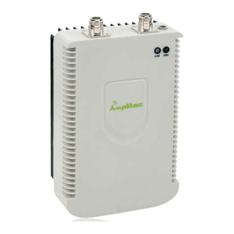
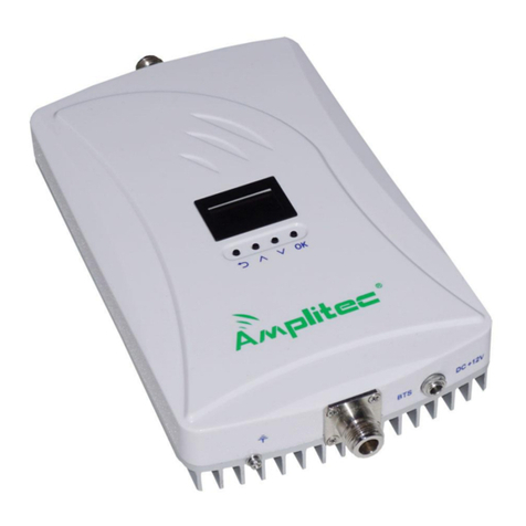
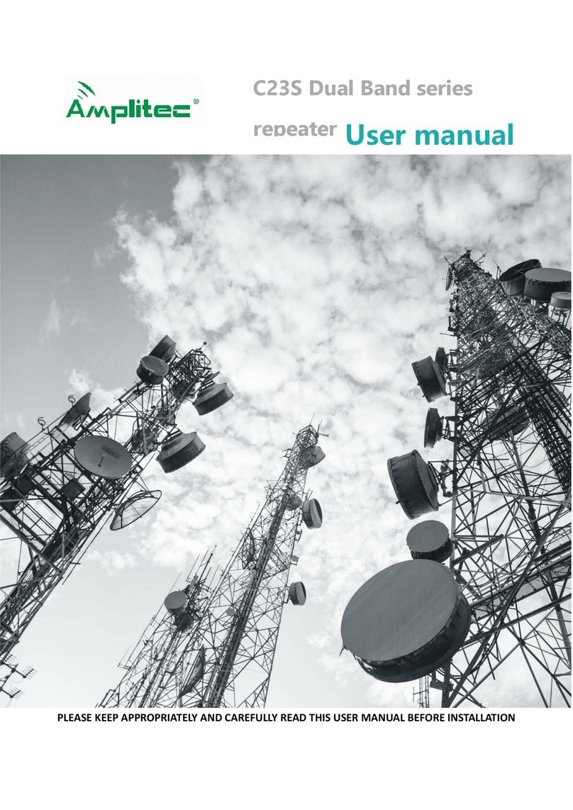
Amplitec C23S Series User manual

PLEASE KEEP APPROPRIATELY AND CAREFULLY READ THIS USER MANUAL BEFORE INSTALLATION
C23S Series Signal Repeater
User Manual

1
Content
PACKAGE CONTENTS..........................................................................................................2
PRODUCT DESCRIPTION.................................................................................................... 2
PRODUCT FEATURES.......................................................................................................... 2
CONNECTOR DESCRIPTION...............................................................................................2
OPERATION AND DISPLAY DESCRIPTION....................................................................3
TECHNICAL SPECIFICATION..............................................................................................8
INSTALLATION GUIDES....................................................................................................... 9
Installation Requirements........................................................................................................................9
Installation tools.........................................................................................................................................9
Installation Steps....................................................................................................................................... 9
Antenna Connection............................................................................................................................... 10
Starting....................................................................................................................................................... 11
MAINTENANCE..................................................................................................................... 11
Operation and maintenance..................................................................................................................11
Notes........................................................................................................................................................... 11
The power supply voltage of the repeater
should meet the standards of security
requirements.
Ensure of grounding, waterproof and
lightning protection when installing the
repeater.
The repeater should be installed and
initiated by professionals.
The user had better not dismantle the
repeater to maintain or replace the
components by himself/herself.
Keep the repeater away from heat source
and do not install it in a confined space.

2
Package Contents
C23S repeater, 1pc 5V2A power adapter, 1pc Installation screws, 1bag U-shape back holder
Product Description
Amplitec C23S dual band series repeater adopts anti-interference, digital ALC, baseband
synch and GPS synch technologies, supporting built-in or external antenna.
This model is equipped with LCD screen, to clearly display parameters and working status like
the working frequency, gain, output power, ISO and ALC alarms. It is with compact size, elegant
design, weight less than 1.1KG, which help to easy installation and maintenance.
Product Features
Display shows all parameters clearly and the button function are more intuitively and faster
Support dual band network for 2G 3G and 4G
Low power consumption, low interference
Digital ALC technology, could limit the output power to ensure stable coverage
Anti-interference, auto isolation detection after start-up and auto self-oscillation elimination
technologies can avoid self-oscillation, which cause interference to the base station
Manual gain attenuation, with 1dB step to attenuate the gain among 1-31dB range
Connector Description
A
B
C
D

3
G
H
F
I
A:Donor antenna port (N-female)
B:Service antenna port(N-female)
C:12V DC power supply port
D:Grounding screw
E:Display screen
F:Return button
G:Upward button
H:Downward button
I:Select and confirm button
Operation and Display Description
a. Functions on Control Panel:
Return button: Return to upper-level page
Up button: Go upward to select
Down button: Go downward to select
OK button: to select and confirm
b. Screen display
After power-on and starting running, the device will display working frequency on the main
menu(The frequency below is just for reference. The actual working frequency of the device will be
E

4
customized as clients require.). It will scroll the working frequency, downlink input and output signal,
gain and alarm on the screen. (As Figure 1)
Figure 1
c. View the Working Frequency Bands
Press UP or DOWN button to move the cursor to the first line(as Figure 2). Then press OK
button to check the working frequency(Figure 3). After that, press RETURN button to go to the
home page.
Figure 2 Figure 3
d. View the Output Power
Move the cursor the second line with the UP and Down button(as Figure 4), press OK button to
check the real-time downlink input and output power(as Figure 5). After that, press RETURN button
to go to the home page.
Figure 4 Figure 5

5
e. View the Gain
Move the cursor to the third line “ GAIN” with UP or DOWN button (as Figure 6) from the home
page, and press OK button to view the real-time gain (as Figure 7). Press the RETURN button back
to the home page.
Figure 6 Figure 7
f. ATT Setting
The default is in Smart Mode, so it will automatically adjust the ATT and manual operation is
not allowed; if you want to set ATT manually, please change it to Manual Mode by moving the
cursor with UP or DOWN button to the forth line “STATUS”, then press OK (as Figure 8), then
navigate the cursor to “MODE” (as Figure 9).
Figure 8 Figure 9
Press OK to enter, “SMART” is on the left side and “MANUAL” is on the right, select “MANUAL”
with UP or DOWN button and press OK to confirm the setting (as Figure 10).
Figure 10

6
Then move the cursor to the third line “Gain ” with UP or DOWN button (as Figure 11), press
OK to enter the ATT setting interface, then select one system, press OK button(as Figure 12).
Figure 11 Figure 12
To increase or decrease the gain value, please press the UP or DOWN button (as Figure 13
and 14); Max. adjustment range is 31dB and the system’s uplink and downlink gain will be adjusted
simultaneously. After adjustment, press the RETURN button back to the home page.
Figure 13 Figure 14
g. Alarm Check
Move the cursor to the forth line “STATUS” from home page, then press OK button to enter (as
Figure 15), then navigate the cursor to “ALARM ITEMS” with UP or DOWN button (as Figure 16).
Figure 15 Figure 16

7
Then press OK to view, select AGC (as Figure17), press OK to view AGC alarm (as Figure18).
Figure 17 Figure 18
Select DL OUTPUT (as Figure 19), press OK button to view DL OUTPUT alarm (as Figure 20).
Figure 19 Figure 20
To remove alarm, if it is in smart mode, the device will make adjustment automatically after
re-powering; if it is in manual mode, you should adjust the outdoor antenna and the gain manually,
until the alarm is eliminated. If all is in OK status, that means it works normally. Press the RETURN
button back to home page after adjustment.
h. Restore Factory Default
Move the cursor to the forth line “STATUS”with UP or DOWN button (as Figure 21), then press
OK button to enter, then navigate the cursor to“DEFAULTS” (as Figure 22), press OK button to
confirm restoring factory default; factory default is under Smart Mode.
Figure 21 Figure 22

8
After factory default, it will detect isolation automatically. To view ISO, move the cursor to the
forth line “STATUS”, press OK button, and select “ISOLATION” (as Figure 23), then press OK
button to view ISO (as Figure 24). After that, press the RETURN button back to home page.
Figure 23 Figure 24
Technical Specification
Items
Uplink
Downlink
Frequency
Band 8
880 ~ 915 MHz
925 ~ 960 MHz
Band 1
1920 ~ 1980 MHz
2110 ~ 2170 MHz
Output Power
Band 8
23±2dBm
23±2dBm
Band 1
23±2dBm
23±2dBm
Gain
Band 8
73±2dB
73±2dB
Band 1
73±2dB
73±2dB
Ripple in Band
Band 8
≤15dB
≤15dB
Band 1
≤10dB
≤10dB
VSWR
Band 8
≤2
≤2
Band 1
≤2
≤2
ATT step of 1dB
(Band 8)
1 ~ 10dB
∣△∣≤1dB
∣△∣≤1dB
10 ~ 20dB
∣△∣≤1.5dB
∣△∣≤1.5dB
20 ~ 25dB
∣△∣≤2dB
∣△∣≤2dB
ATT step of 1dB
(Band 1)
1 ~ 10dB
∣△∣≤1dB
∣△∣≤1dB
10 ~ 20dB
∣△∣≤1.5dB
∣△∣≤1.5dB
20 ~ 25dB
∣△∣≤2dB
∣△∣≤2dB
ALC Active 10dB
∣△∣≤2dB
∣△∣≤2dB
Intermodulation
Products
Band 8(CW)
≤ -36dBc
≤ -36dBc
Band 1(CW)
≤ -36dBc
≤ -36dBc
Spurious
Emission
9KHz~1GHz
≤ -36dBm
≤ -36dBm
1GHz~12.75GHz
≤ -30dBm
≤ -30dBm
Noise Figure
Band 8
≤8dB
≤8dB
Band 1
≤8dB
≤8dB
Time Delay
Band 8
≤0.5μs
≤0.5μs
Band 1
≤0.5μs
≤0.5μs
Power Supply
DC: +12V/2A
Power Consumption
<20W

9
Installation Guides
Installation Requirements
1) With Stable and independent power supply.
2) The repeater should be installed in the space without corrosive gas, smokes and leaky liquids.
3) The repeater should be installed on the wall that is ventilated, waterproof, lightning-proof and
without sunshine.
4) The height of the installation site should be safe and easy for cabling, maintaining, dissipating
heat.
Installation tools
No.
Items
Q’ty
Remarks
1
Impact drill
1
Drill holes on wall, self-provided
2
Wrench
1
Reinforce the interface connection, self-provided
3
U-shape holder, expansion
pipe and screws
4
Fix the device, included in the package
4
Mobile phone for testing
1
Test installation effectiveness, self-provided
5
Multimeter
1
Test voltage and wiring connection, self-provided
6
Screwdriver
1
Tighten or fasten the device, self-provided
7
Waterproof tape
A few
Prevent liquid from leaking into the feeder
interface, self-provided
Installation Steps
This repeater should be installed on a hard, firm and flat surface, its installation steps are as
follows:
1) Select a proper installation site according to the size and installation requirements of the
repeater.
2) Estimate and mark the sites of U-shaped back holder installation holes. Drill holes with the
impact drill. Sizes of the holes are 7mm. The expected sites are as follow: (unit: mm)

10
3) Put the expansion plug(size: 8mm) into the 4 drilled holes.
4) As shown in the figure, align the fixing holes of the U-shaped back holder with corresponding
holes on the wall. Then drive 4 pcs of M6*40 screws into the expand plugs with screwdriver. Finally,
hang the repeater firmly on the U-shaped back holder.
Antenna Connection
Choose suitable outdoor and indoor antennas according to the characteristic of the coverage
area. Installation and connection of the antennas should follow the requirements as following:
1) The outdoor antenna should be installed at the place with the strongest signal and aiming
towards BTS.
2) The length of the cable, which connects the outdoor antenna and the repeater, should be less
than 20 meters.
3) Wrap the waterproof tape around the connection part of the outdoor antenna and outdoor
cable, keeping it away from water oxidation and corrosion.
4) The height difference between the indoor and outdoor antennas should be over 5m, and the
transmit direction of indoor antenna should not aim at the outdoor antenna.
5) It will be better if there is a wall between outdoor and indoor antennas.
6) Outdoor antenna should connect to BTS port of the repeater, while indoor antenna to the MS
port.

11
Starting
1) If possible, please wire up the grounding screw of the repeater to the ground wire of the power
line.
2) Make sure the feeder cables between repeater and antennas are firmly connected.
3) Connect the DC plug of the 5V/2A power adapter to the DC+5V port of the repeater. Then put
AC plug connecting to the nearby 220V power outlet.
4) Check if the repeater can work normally or not, by checking the operation parameters on the
screen, according to the guides of the previous “Operation and Display Description”part.
5) Test the signal intensity and call quality with a mobile phone in the coverage area.
Maintenance
Operation and maintenance
Power supply
Please make sure the voltage and frequency of AC power is in conformity with that of the repeater.
Component replacement
Please do not maintain or replace the components by yourself, in case you may get an electric
shock. Only authorized personnel can maintain or replace the components.
Waterproof and moisture-proof
Please don’t turn on the equipment in a humid environment.
Notes
Power-off is recommended in the following situations:
Power supply is abnormal.
Liquid flows into the device.
Working conditions are abnormal such as overheating, strange smell or foreign matters
Performance is decreased
Too close to the fire

1
Manufacturer: Foshan Amplitec Tech Development Co.,Ltd
Addr: 4th Floor, 4th Building, No. 60 of Langbao West Rd, Zhangcha Foshan, China,528000
Tel:0757-83308238,Fax:0757-83123923
Email:[email protected], Website:www.amplitec.net
Other manuals for C23S Series
1
Table of contents
Other Amplitec Repeater manuals

Amplitec
Amplitec C20W Series User manual

Amplitec
Amplitec C15-WCDMA User manual

Amplitec
Amplitec W20-GSM User manual

Amplitec
Amplitec C23S Series User manual

Amplitec
Amplitec C10 Series User manual

Amplitec
Amplitec C20M-5B Series User manual

Amplitec
Amplitec C10 Series User manual

Amplitec
Amplitec C23S-EGSM User manual