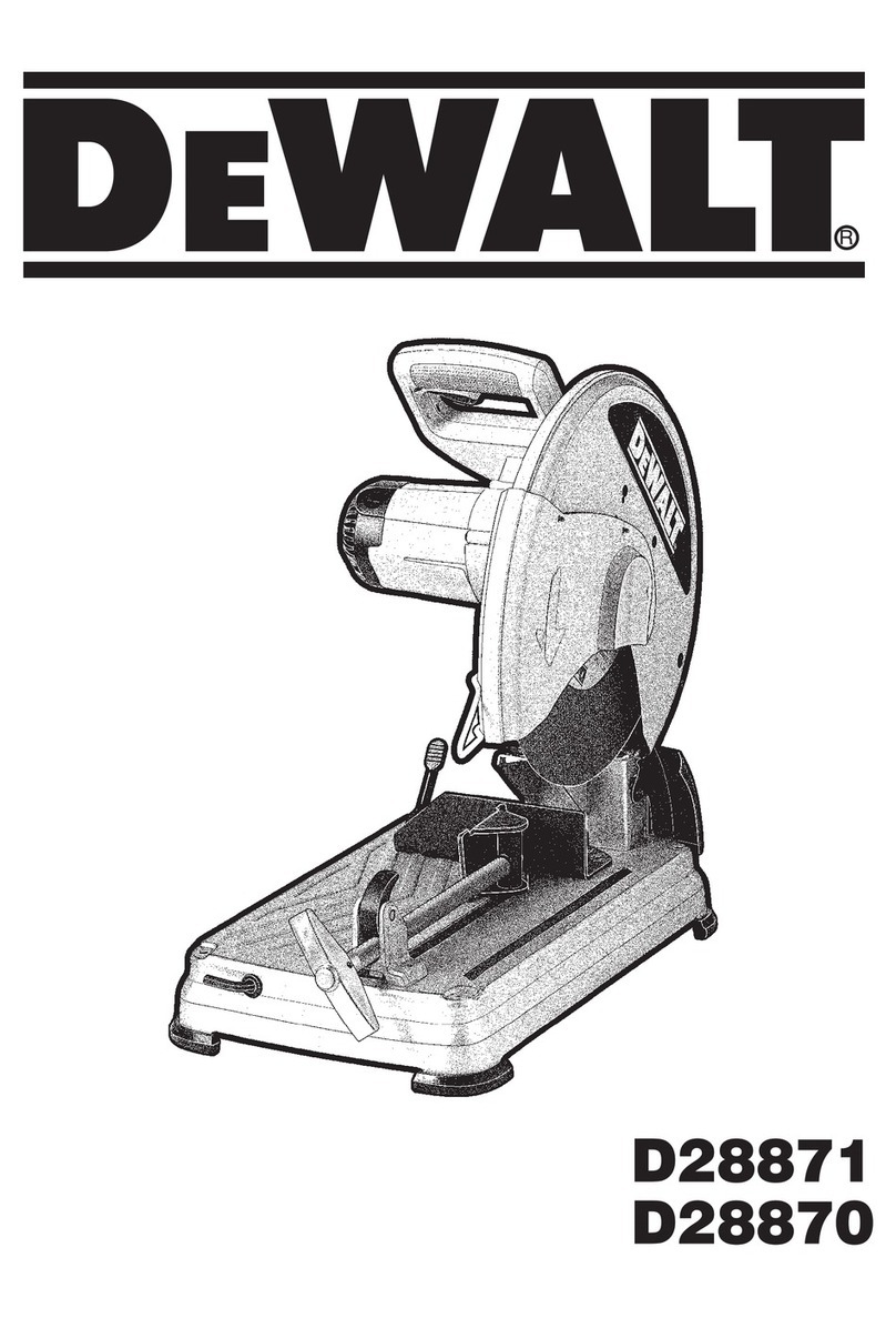
DeWalt D28710 User manual

If you have questions or comments, contact us.
Pour toute question ou tout commentaire, nous contacter.
Si tiene dudas o comentarios, contactenos.
INSTRUCTION MANUAL
GUIDE D'UTILISATION
MANUAL DE INSTRUCCIONES
INSTRUCTIVO DE OPERACION, CENTROS DE SERVICIO Y
P©LIZA DE GARANTiA. ADVERTENOIA" LEASE ESTE
INSTRUCTIVOANTES DE USAR EL PRODUCTO.
E ®
D28710 Heavy-Duty 14" (355mm) Chop Saw
Scie fendeuse a service intensif de 355 mm (14") D28710
Sierra circular estacionaria de 355 mm (14 pulg.)
para trabajo pesado D28710

F Definitions: Safety Guidelines \
The definitions below describe the level of severity for each
signal word. Please read the manual and pay attention to these
symbols.
i_,DANGER: Indicates an imminently hazardous situation
which, if not avoided, will result in death or serious injury.
i_ WARNING: Indicates a potentially hazardous situation which,
if not avoided, could result in death or serious injury.
i_,CAUTION: Indicates a potentially hazardous situation which, if
not avoided, may result in minor or moderate injury.
NOTICE: Indicates a practice not related to personal injury
which, if not avoided, may result in property damage.
\ i.
IF YOU HAVE ANY QUESTIONS OR COMMENTS ABOUT THIS OR
ANY DEWALT TOOL, CALL US TOLL FREE AT: 1-800-4-DEWALT
(1-800-433-9258).
Important Safety Instructions
_WARNING: Read all instructions before operating
product. Failure to follow all instructions listed below
may result in electric shock, fire and/or serious injury.
SAVE THESE INSTRUCTIONS
Double Insulation
Double insulated tools are constructed throughout with two separate
layers of electrical insulation or one single layerof reinforced insulation
between you and the tool's electrical system. Tools built with this
insulation system are not intended to be grounded. As a result, your
tool is equipped with a two prong plug which permits you to use
extension cords without concern for maintaining aground connection.
NOTE: Double insulation does not take the place of normal safety
precautions when operating this tool. The secondary insulation
system is for protection against injury resulting from a possible failure
of the primary insulation within the tool.
_CAUTION: WHEN SERVICING USE ONLY IDENTICAL
REPLACEMENT PARTS. Repair or replace damaged cords.
Polarized Plugs
Polarized plugs (one blade is wider than the other) are used on
equipment to reduce the risk of electric shock. When provided, this
plug will fit in the polarized outlet only one way. If the plug does not
fit fully in the outlet, reverse the plug. If it still does not fit, contact a
qualified electrician to installthe proper outlet. Do not change the plug
in any way.
• KEEP GUARDS IN PLACE and in working order.
•REMOVE ADJUSTING KEYS AND WRENCHES. Form habit
of checking to see that keys and adjusting wrenches are removed
from tool before turning it on.
• KEEP WORKAREA CLEAN. Cluttered areas and benches invite
injuries.
•DON'T USE IN DANGEROUS ENVIRONMENT. Don't use
power tools in damp or wet locations, or expose them to rain.
Keep work area well lighted.
•KEEP CHILDREN AWAY. All visitors should be kept at a safe
distance from work area.
• MAKE WORKSHOP KID PROOF with padlocks, master
switches, or by removing starter keys.
•DON'T FORCE TOOL. It will do the job better and safer at the
rate for which it was designed.
• USE RIGHT TOOL. Don't force tool or attachment to do ajob for
which it was not designed.
•USE PROPER EXTENSION CORD. An extension cord must
have adequate wire size (AWG or American Wire Gauge) for
safety. The smaller the gauge number of the wire, the greater the
capacity of the cable, that is 16 gauge has more capacity than
18 gauge. An undersized cord will cause a drop in line voltage

resultinginlossofpowerandoverheating.Whenusingmorethan
oneextension to make up the total length, be sure each individual
extension contains at least the minimum wire size. The following
table shows the correct size to use depending on cord length and
nameplate ampere rating. If in doubt, use the next heavier gauge.
The smaller the gauge number, the heavier the cord.
Ampere Rating
Minimum Gauge for Cord Sets
Volts Total Length of Cord in Feet (meters)
120V 25 (7.6) 50 (15.2) 100 (30.5) 150 (45.7)
240V 50 (15.2) 100 (30.5) 200 (61.0) 300 (91.4)
Than
0
6
10
12
WEAR
More Not More
Than
6
10
12
16
PROPER
AWG
18 16 16 14
18 16 14 12
16 16 14 12
14 12 NotRecommended
• APPAREL. Do not wear loose clothing,
neckties, rings, bracelets, or other jewelry which may get caught in
moving parts. Nonslip footwear is recommended. Wear protective
hair covering to contain long hair. Air vents often cover moving
parts and should also be avoided.
•ALWAYS USE SAFETY GLASSES which meet the ANSI Z87.1
requirements. Also use face or dust mask if cutting operation is
dusty. Everyday eyeglasses only have impact resistant lenses, they
are not safety glasses.
•SECURE WORK. Use clamps or a vise to hold work. It's safer
than using your hand and it frees both hands to operate tool
•DON'T OVERREACH. Keep proper footing and balance at all
times.
•MAINTAIN TOOLS WITH CARE. Keep tools sharp and clean
for best and safest performance. Follow instructions for lubricating
and changing accessories.
•DISCONNECT TOOLS before servicing; when changing
accessories, such as blades, bits, cutters, and the like.
•REDUCE THE RISK OF UNINTENTIONAL STARTING. Make
sure switch is in off position before plugging in.
• USE RECOMMENDED ACCESSORIES. Consult the instruction
manual for recommended accessories. The use of improper
accessories may cause risk of injury to persons.
•NEVER STAND ON TOOL. Serious injury could occur if the tool
is tipped or if the cutting tool is unintentionally contacted.
•CHECK DAMAGED PARTS. Before further use of the tool, a
guard or other part that is damaged should be carefully checked
to determine that it will operate properly and perform its intended
function -- check for alignment of moving parts, binding of moving
parts, breakage of parts, mounting, and any other conditions that
may affect its operation. A guard or other part that is damaged
should be properly repaired or replaced.
•NEVER LEAVE TOOL RUNNING UNATTENDED. TURN
POWER OFF. Don't leave tool until it comes to a complete stop.
Additional Safety Rules for Chop Saw
•Always wear proper eye and respiratory protection.
•Before using, inspect the cutting wheel for cracks or flaws.
If such a crack or flaw is evident, discard the wheel. The
wheel should also be inspected whenever you think the tool
may have been dropped. Flaws may cause wheel breakage.
•When starting the tool with a new or replacement wheel
or if you are unsure of the condition of the wheel, hold the
tool in a well protected area and let H run for one minute. If
the wheel has an undetected crack or flaw, ff should burst
in less than one minute. Never start the tool with a person in line
with the wheel This includes the operator.
•In operation, avoid bouncing the wheel or giving it rough
treatment. If this occurs, stop the tool and inspect the wheel for
cracks or flaws.
• Clean your chop saw periodically following the procedure in this
manual.
• Do not remove wheel guards or base.
• ALWAYS USE THE VISE OR SPECIAL FIXTURE TO CLAMP
WORK SECURELY. Other aids such as spring, bar, or C-clamps
may be appropriate for certain sizes and shapes of workpiece. Use
care in selecting and placing these clamps and make a dry run
before making a cut.
• Use only 14" type 1 wheels rated at 4100 rpm orhigher.
• Allow cut off parts to cool before handling.
• Do not attempt to cut wood or plastic with this tool
•NEVER CUT MAGNESIUM WITH THIS TOOL.
• Use chop saw in a well-ventilated area.
• Turn chop saw off before removing any pieces from the base.
•DO NOT CUT ELECTRICALLY LIVE MATERIAL.
•DO NOT USE CIRCULAR SAW BLADES OR ANY OTHER
TOOTHED BLADES WITH THIS TOOL. Serious injury may
result.
•DO NOT OPERATE THIS TOOL NEAR FLAMMABLE
LIQUIDS, GASES OR DUST. Sparks or hot chips from cutting or
arcing motor brushes may ignite combustible materials.
• Do not use the side of the abrasive wheel as a deburring grinder.
This will substantially weaken the wheel creating an unsafe
condition. The wheel may come apart.
_CAUTION: Wear appropriate hearing protection during use.
Under some conditions and duration of use, noise from this product
may contribute to hearing loss.
ACAUTION: Spark deflector will get hot. Avoid touching or
adjusting while hot. Keep cordset and materials away from spark
deflector.
AWARNING: Some dust created by power sanding, sawing,
grinding, drilling, and other construction activities contains chemicals
known to the State of California to cause cancer, birth defects, or
other reproductive harm. Some examples of these chemicals are:
• lead from lead-based paints,
• crystalline silica from bricks and cement and other masonry
products, and
• arsenic and chromium from chemically-treated lumber (CCA).
Your risk from these exposures varies, depending on how often you
do this type of work. To reduce your exposure to these chemicals:
work in a well ventilated area, and work with approved safety
equipment, such as those dust masks that are specially designed to
filter out microscopic particles.
•Avoid prolonged contact with dust from power sanding,
sawing, grinding, drilling, and other construction activities.
Wear protective clothing and wash exposed areas with
soap and water. Allowing dust to get into your mouth, eyes, or
lay on the skin may promote absorption of harmful chemicals.
_,WARNING: Use of this tool can generate and/or disperse dust,
which may cause serious and permanent respiratory or other injury.
Always use NIOSH/OSHA approved respiratory protection appropriate
for the dust exposure. Direct particles away from face and body.
For your convenience and safety, the following warnings are on your
Heavy-Duty 14" (355mm) Chop Saw:
AFOR SAFE OPERATION READ THE INSTRUCTION
MANUAL.
DO NOT USE TOOTHED BLADES.
USE ONLY REINFORCED WHEELS RATED
4100 RPM OR HIGHER.
WHEN SERVICING USE ONLY IDENTICAL
REPLACEMENT PARTS.
ALWAYS: WEAR EYE PROTECTION, USE GUARDS,
CLAMP WORK IN VISE, USE PROPER RESPIRATORY
PROTECTION.
DO NOT EXPOSE TO RAIN OR USE IN DAMP
LOCATIONS.

FIG. 1

FEATURES (FIG. 1, 4)
A. Chain lock J. Wheel
B. Spark deflector screw K. Guard
C. Spark deflector L. Wheel lock lever
D. Base M. Depth stop bolt
E. Fence N. Trigger switch
F. Vise O. Padlock hole
G. 8mm hex wrench R Jam nut
H. Crank Q. Fence bolts
I. Vise lever
Power Supply
Be sure your power supply agrees with the nameplate marking.
120 volts, "60 Hz" means alternating current (normal 120 volt, 60 Hz
house current).
A voltage decrease of more than 10% will cause a loss of power and
overheating.
Cutting Capacity
The wide vise opening and high pivot point provide cutting capacity
for many large pieces. Use the cutting capacity chart to determine
total maximum size of cuts that can be made with a new wheel.
,_t,WARNING: CERTAIN LARGE, CIRCULAR OR IRREGULARLY
SHAPED OBJECTS MAY REQUIRE ADDITIONAL HOLDING
MEANS IF THEY CANNOT BE HELD SECURELY IN VISE.
J_,WARNING: DO NOT CUT MAGNESIUM WITH THIS TOOL.
MAXIMUM CUTTING CAPACITY
NOTE: Capacity shown on chart assumes no wheel wear and optimum fence position.
Workpiece Shape: O A __
90° Cutting Angle A = 5" A = 4.75"
(130mm) (120mm) A = 5-3/8"
(137mm)
AxB
4.5" x 5"
(115mm x 130mm
4" x 7-5/8"
(102mm x 194mm
3" x 9"
(76mm x 229mm)
4.5" x 4.25"
(115mm x 107mm
45° Cutting Angle A = 4.5" A = 4.25" A = 4.5"
(115mm) (107mm) (115mm)

Standard Equipment
1 14" (355mm) metal cutting abrasive wheel
1 Wheel wrench
1 Instruction manual
To Carry (Fig. 1)
Fold down unit to position where you can carry the saw. Use the chain
lock (A)to lock arm down.
Unlocking (Fig. 1)
Tounlock tool and raise head, depress motor arm slightly and unlock
the chain lock (A). Motor arm will then pivot upward.
Material Clamping and Supporting
• Angles are best clamped and cut with both legs resting against
base.
• A spacer block slightly narrower than the workpiece can be
used to increase wheel utilization (Fig. 2).
• Long workpieces must be supported by a block so it will be level
with top of base (Fig. 3). The cut-off end should be free to fall
downward to avoid wheel binding.
FIG. 2 DIAMETEROFWORKPIECE
E
_¢7-_._ SPACER
LOCK
iiiiiiiiiiiiiiiiiiiiiiiiiiiiiiiiiiiiiiiiiiiiiiiiiiiiiiiiiiiiiiiiiiiiiiiiiiiii
WIDTHOFSPACERBLOCK
FIG.3
CUT-OFF END
BLOCK
Spark Deflector Adjustment (Fig. 1)
To best deflect sparks away from surrounding persons and
materials, loosen the screw (B), adjust the spark deflector (C) and
then retighten screw. Do not allow cordset to come into contact with
deflector or sparks as damage to cordset may occur.
FIG.4
FORWARD

Vise Operation (Fig. 4)
The vise (F) has a quick-travel feature. To release the vise when it is
clamped tightly, turn the crank (H)counterclockwise one or two times
to remove clamping pressure. Lift vise lever (I)up. Pull crank assembly
out as far as desired. Vise may be pushed forward into work without
cranking. Lower vise lever (I) then tighten vise (F) on work by using
crank (H).
Fence Operation
_WARNING: Turn off and unplug the tool before making
any adjustments or removing or installing attachments or
accessories. Be sure the trigger switch is in the OFF position.
The fence (E)can be adjusted two ways: to change desired cutting
angle and to change spacing between the fence and vise.
TO CHANGE THE DESIRED CU'I-I'ING ANGLE (FIG. 5, 6)
Use the wrench provided to loosen (do not remove) the two fence
bolts (Q).Align the desired angle indicator line with the slot line (R) in
the base (D).Securely tighten both fence bolts before use.
FIG.5 G :Q
For more accurate square cuts, disconnect the power supply, loosen
the two fence bolts, push arm down until wheel extends into base.
Place a square against the wheel and adjust fence against the square.
Securely tighten both fence bolts before use.
Q J
FIG.6
When making a miter cut, the vise (F) may not clamp securely,
depending on the thickness of the workpiece and the miter angle.
Other aids (such as spring, bar or C-clamps) will be necessary to
secure the workpiece to the fence when making these cuts.
TO CHANGE SPACING BETWEEN THE FENCE AND VISE
Using the wrench provided, loosen and remove the two fence bolts
(Q). Adjust the fence (E)to desired locations. Insert both fence bolts
in provided locations. Securely tighten both fence bolts before use.
Depth Stop (Fig. 1)
Depth stop is set at the factory for a new 14" (355mm) wheel to
prevent wheel from cutting into the supporting surface. To allow more
depth of cut, use the 8mm hex wrench (G) provided to loosen the
depth stop bolt (M) and raise bolt to desired height and then turn jam
nut (P) clockwise until seated firmly on the casting. Securely tighten
the depth stop bolt before use.
_CAUTION: When changing to a new wheel, readjust depth stop to
original position to prevent cutting into supporting surface.

Trigger Switch (Fig. 1)
To start the tool, depress the trigger switch (N). To turn the tool off,
release the trigger switch. Keep hands and material from wheel until
it has coasted to a stop.
To prevent unauthorized use of tool, install a standard padlock (not
included) into the padlock hole (O) located in the trigger.
Removal and Installation of Wheels
(Fig. 1, 7, 8)
_WARNING: Turn off and unplug the tool before making
any adjustments or removing or installing attachments or
accessories. Be sure the trigger switch is in the OFF position.
Do not make any adjustment while the wheel is in motion.
Do not make any adjustment while chop saw is plugged into
power supply.
1. Push in wheel lock lever (L) and rotate wheel (J) by hand until
wheel lock lever engages slot in inside flange (S)to lock wheel.
Loosen the bolt (T)counterclockwise in the center of the abrasive
wheel with the 8mm hex wrench (G). Bolt has right-hand thread.
2. Remove the bolt (T),washer (U), outside flange (V)and old wheel
(d).
3. Make sure flange surfaces are clean and flat. Install the new
abrasive wheel by reversing the above steps.
4. Do not overtighten bolt.
FIG.7
,_WARNING: Check the work surface that the chop saw rests on
when replacing with a new abrasive wheel. It is possible that the
wheel may contact ANY ITEMS OR STRUCTURE THAT EXTENDS
ABOVE work surface (under the base) when the arm is fully lowered.
FIG.8 J V
Mounting (Fig. 9, 10)
_CAUTION: Tool must be supported on stable, level, non-skid
surface to prevent unexpected movement when operating.
PROCEDURE FOR PERMANENT MOUNTING
1. Drill two holes 5/16" (8 mm) FIG.9 ,,................... ,
through the work surface o ,
i
(Fig. 9). ',
i
2. Insert 1/4-20 screws down ',
through the holes in the
base and through holes in
mounting surface. The
approximate length of
the screws should be the
thickness of the mounting
surface plus 4" (102 mm).
3. Tighten both screws securely.
................. /

CRADLE MOUNTING
(FIG. 10)
1. Cut two boards
approximately 20" long x
2" high x 4" wide (508 x
50.8 x 101.6mm).
2. Place the chop saw at
desired work location.
3. Place boards tightly
alongside and nail to work
surface.
Operation
Tips for More
Accurate Cuts
FIG. 10
• Allow the wheel to do the cutting. Excessive force will cause
the wheel to glaze reducing cutting efficiency and/or to deflect
causing inaccurate cuts.
• Properly adjust fence angle.
• Make sure material is laying flat across base.
• Properly clamp material to avoid movement and vibration.
MAINTENANCE
Motor Brush Inspection and Replacement
(Fig. 11)
_WARNING: Turn off and unplug the tool before making
any adjustments or removing or installing attachments or
accessories. Be sure the trigger switch is in the OFF position.
FIG. 11 W
S 12I
(6mm)
Brushes should be regularly inspected for wear. To inspect brushes,
remove brush cap (W). Brushes (X)should slide freely in brush box.
If brushes are worn down to .2" (6mm) as shown in Figure 10 they
should be replaced. To reinstall, push new brush back into brush
box. If replacing existing brush, maintain same orientation as when
removed. Replace the brush cap (do not overtighten).
Cleaning
AWARNING: Blow dirt and dust out of allair vents with clean, dry air
at least once a week. Tominimize the risk of eye injury, always wear
ANSI Z87.1 approved eye protection when performing this.
_WARNING: Never use solvents or other harsh chemicals for
cleaning the non-metallic parts of the tool These chemicals may
weaken the plastic materials used in these parts. Use a cloth
dampened only with water and mild soap. Never let any liquid get
inside the tool,"never immerse any part of the tool into a liquid.
Repairs
To assure product SAFETY and RELIABILITY, repairs, maintenance
and adjustment should be performed by authorized service centers
or other qualified service organizations, always using identical
replacement parts.

Lubrication
Closed-type, grease-sealed ball bearings are used throughout. These
bearings have sufficient lubrication packed in them at the factory to
last the life of the chop saw.
Accessories
_WARNING: Since accessories, other than those offered by
DEWALT, have not been tested with this product, use of such
accessories with this tool could be hazardous. Toreduce the risk of
injury, only DEWALT recommended accessories should be used with
this product.
Use only high-strength Type 1 organic bonded wheels rated
4100 rpm or higher.
Recommended accessories for use with your tool are available at
extra cost from your local dealer or authorized service center. If you
need assistance in locating your local dealer or authorized service
center contact: DEWALT Industrial Tool Co., 701 East Joppa Road,
Baltimore, MD 21286 or call 1-800-4-DEWALT (1-800-433-9258).
Three Year Limited Warranty
DEWALTwill repair,without charge, any defects due to faulty materials
or workmanship for three years from the date of purchase. This
warranty does not cover part failure due to normal wear or tool
abuse. For further detail of warranty coverage and warranty repair
information, visit www.dewalt.com or call 1-800-4-DEWALT (1-800-
433-9258). This warranty does not apply to accessories or damage
caused where repairs have been made or attempted by others. This
warranty gives you specific legal rights and you may have other rights
which vary in certain states or provinces.
In addition to the warranty, DEWALT tools are covered by our:
1 YEAR FREE SERVICE
DEWALT will maintain the tool and replace worn parts caused by
normal use, for free, any time during the first year after purchase.
90 DAY MONEY BACK GUARANTEE
If you are not completely satisfied with the performance of your
DEWALT Power Tool, Laser, or Nailer for any reason, you can return
it within 90 days from the date of purchase with a receipt for a full
refund - no questions asked.
LATIN AMERICA: This warranty does not apply to products sold
in Latin America. For products sold in Latin America, see country
specific warranty information contained in the packaging, call the local
company or see website for warranty information.
FREE WARNING LABEL REPLACEMENT: If your warning labels
become illegible or are missing, call 1-800-4-DEWALT (1-800-433-
9258) for a free replacement.
D2871014"3_., CHOPSAW
s_.
10

TROUBLE! TOOL WILL NOT START Troubleshooting Guide
WHAT'S WRONG?
1. Tool not plugged in.
2. Fuse blown or circuit breaker tripped.
3. Cord damaged.
4. Brushes worn out.
TROUBLE! TOOL MAKES UNSATISFACTORY CUTS
WHAT TO DO...
1. Plug in saw.
2. Replace fuse or reset circuit breaker.
3. Have cord replaced by authorized service center.
4. Replace brushes.
WHAT'S WRONG?
1. Glazed wheel.
2. Workpiece incorrectly placed or clamped.
TROUBLE! BLADE DOES NOT COME UP TO SPEED
WHAT TO DO...
1. Dress the wheel or replace with a new one.
2. Firmly clamp and support workpiece.
WHAT'S WRONG?
1. Extension cord too light or too long.
2. Low voltage.
3. Low generator voltage.
TROUBLE! TOOL VIBRATESEXCESSIVELY DURING CUT
WHAT TO DO...
1. Replace with adequate size cord. See chart on page 2.
2. Contact your electric company.
3. Check generator output voltage. Reduce number of tools
powered by the generator.
WHAT'S WRONG?
1. Tool not mounted securely to stand or work bench.
2. Damaged wheel.
3. Workpiece not clamped properly.
WHAT TO DO...
1. Tighten all mounting hardware.
2. Replace wheel.
3. Refer to Material Clamping and Supporting, page 6.
11

Troubleshooting Guide...
TROUBLE! DOES NOT MAKE ACCURATE CUTS
WHAT'S WRONG?
1. Fence not adjusted correctly.
2. Wheel is not square to fence.
3. Excessive force used to make cut.
4. Workpiece moving.
TROUBLE! CANNOT MOVE ARM
WHAT'S WRONG?
1. Chain lock is engaged.
TROUBLE! MATERIAL MOVES DURING CUT
WHAT'S WRONG?
1. Fence slipping or workpiece incorrectly placed or clamped.
2. Vise too loose.
3. Excessive cutting force.
WHAT TO DO...
1. Check and adjust. See Fence Operation on page 7.
2. Check and adjust.
3. Reduce cutting force; let the wheel do the work.
4. Clamp workpiece securely. See Material Clamping and
Supporting, page 6. Make sure material is laying flat against
the base.
WHAT TO DO...
1. Push down slightly on the arm, unlock the chain lock and
raise arm.
WHAT TO DO...
1. See Material Clamping and Supporting, page 6.
2. Tighten vise clamping.
3. Reduce cutting force.
12

D_finitions : lignes directrices en
mati_re de s_curit_
Les definitions ci-dessous decrivent le niveau de danger pour
chaque mot-indicateur employe. Lire le mode d'emploi et porter
une attention particuliere a,ces symboles.
i_DANGER :indique une situation dangereuse imminente qui,
si elle n'est pas evitee, entraTnera la mort ou des blessures
graves.
_AVERTISSEMENT :indique une situation potentie//ement
dangereuse qui, si e//e n'est pas evitee, pourrait entra_ner /a
mort ou des blessures graves.
i_ATTENTION :indique une situation potentie//ement
dangereuse qui, si e//e n'est pas evitee, pourrait entra_ner des
blessures I_g_res ou modifies.
AVIS :indique une pratique ne posant aucun risque de
dommages corporels mais qui par contre, si rien n'est far
pour /'eviter, pourrait poser des risques de dommages
materiels.
POUR TOUTE QUESTION OU REMARQUE AU SUJET DE CET
OUTIL OU DE TOUT AUTRE OUTIL DEWALT, COMPOSER LE
NUMFt:ROSANS FRAIS : 1-800-4-DEWALT (1-800-433-9258).
Consignes de s_curit_ importantes
AVERTISSEMENT :life toutes les directives avant
d'utiliser le produit. Negliger de suivre toutes les
directives suivantes peut entraFner des risques de
chocs electriques, d'incendie et/ou de blessures
graves.
CONSERVER CES DIRECTIVES
Double isolation
Afin de proteger I'utilisateur contre les decharges electriques, les outils
a,double isolation sont completement recouverts de deux couches
distinctes d'isolant electrique ou d'une simple epaisseur renforcee
de matiere isolante. Les outils comportant ce systeme d'isolation ne
sont pas congus pour @tremis a,la terre. L'outil est donc dote d'une
prise a,deux broches qui permet d'utiliser des rallonges sans avoir a,
se soucier de maintenir une connexion a, la terre.
REMARQUE : le fait que cet outil soit muni d'une double isolation ne
signifie pas que I'utilisateur peut cesser de respecter les consignes
de s6curite qui s'imposent. L'isolation secondaire offre une protection
contre tout dommage corporel pouvant resulter d'une defaillance
electrique possible du systeme primaire d'isolation interne.
AATTENTION :EN CAS DE REPARATION, UTILISER UNIQUEMENT
DES PIECES DE RECHANGE IDENTIQUES, Reparer ou remplacer les
cordons d'alimentation endommages,
Fiches polaris_es
Certains appareils comportent des fiches polarisees (c'est-a,-dire
qu'une lame est plus large que I'autre) afin de reduire le risque de
choc electrique. Lorsqu'elle est presente, cette fiche ne se branche
que d'une seule fagon dans une prise de courant polarisee. Si la fiche
ne s'insere pas totalement dans la prise de courant, I'inverser. Si elle
ne s'insere toujours pas dans la prise, demander a,un electricien
competent d'installer une fiche polarisee. Ne pas remplacer la fiche.
•GARDER LES DISPOSITIFS DE PROTECTION EN PLACE et
en bon etat de fonctionnement.
• RETIRER LES CLE-S DE RE-GLAGE ; prendre /'habitude de
s'assurer que les cles de reglage sont retirees de I'outil avant de le
demarrer,
13

• GARDER L'AIREDE TRAVAIL PROPRE; les espaces de travail
et les etablis encombres sont propices aux blessures.
•NE PAS UTILISER L'OUTIL DANS UN ENVIRONNEMENT
DANGEREUX ; ne pas exposer I'outil a la pluie, ni I'utiliser clans
des endroits humides ou detrempes. Garder I'aire de travail bien
eclairee.
•TENIR LES ENFANTS A L'E-CART; s'assurer que personne ne
s'approche de I'aire de travail.
•S'ASSURER QUE L'ATELIER EST SUR POUR LES ENFANTS;
utiliser des cadenas, des interrupteurs centraux ou enlever les
commandes de demarrage.
•NE PAS FORCER L'OUTIL ; pour obtenir de meilleurs resultats
etprevenir les risques de blessure, laisser I'outil couper a la vitesse
pour laquelle il a ete conqu.
•UTILISER L'OUTIL APPROPRIE- ; ne pas forcer I'outil ou
I'accessoire, ni I'utiliser pour des travaux autres que ceux pour
lesquels ila ete conqu.
•UTILISER LES RALLONGES APPROPRIEES ; pour la
s6curit6 de I'utilisateur, utiliser une rallonge de calibre
ad_quat (AWG, American Wire Gauge [calibrage am6ricain
normalis6 des ills 61ectriques]). Plus le calibre est petit, et
plus sa capacite est grande. Un calibre 16, par exemple, a une
capacite superieure a un calibre 18. L'usage d'une rallonge de
calibre insuffisant causera une chute de tension qui entra_nera
perte de puissance et surchauffe. Si plus d'une rallonge est utilisee
pour obtenir une certaine Iongueur, s'assurer que chaque rallonge
presente au moins le calibre de filminimum. Le tableau ci-dessous
illustre les calibres a utiliser selon la Iongueur de rallonge et
I'intensite nominale indiquee sur la plaque signaletique. En cas
de doute, utiliser le calibre suivant. Plus le calibre est petit, plus la
rallonge peut supporter de courant.
Calibres minimaux des rallonges
Longueur totale de cordon
en metres (pieds)
Intensit_
(en amperes)
volts
120 V
240 V
Sup_rieur aInf_rieur
0 6
6 10
10 12
12 16
7,6
(25)
15,2
(50)
18
18
16
14
15,2 30,5 45,7
(50) (100) (150)
30,5 61,0 91,4
(100) (200) (300)
AWG
16 16 14
16 14 12
16 14 12
12 Non recommande
•PORTER DES V£-TEMENTS APPROPRIE-S ; ne pas porter
de v_tements amples ni de gants, de cravate, de bague, de
bracelet ou d'autres b_oux, car ceux-ci peuvent rester coinces
dans les pieces mobiles. Le port de chaussures antiderapantes
est recommande. Couvrir ou attacher les cheveux longs. Se tenir
doigne des events puisque ces demiers pourraient cacher des
pioces mobiles.
•TOUJOURS UTILISER DES LUNETTES DE PROTECTION
conformes aux normes ANSI Z87.1. Utiliser aussi un masque
antipoussieres si la decoupe dolt en produire beaucoup. Les
lunettes ordinaires ne peuvent que proteger contre les impacts,
ce ne sont pas des lunettes de protection.
•ARRIMER LA PIt-CEA TRAVAILLER. Pour ce, utiliser un serre-
joint ou un etau. C'est plus sOr que de le faire manuel/ement et
cela laisse les mains libres pour utiliser I'outil.
•NE PAS EFFECTUER DE TRAVAUX HORS DE PORTEE.
Les pieds doivent rester bien ancres au sol afin de maintenir son
equilibre en tout temps.
14

• BIEN ENTRETENIR L'OUTIL ; afin d'obtenir de mei//eurs
resultats et faire preuve de prudence, garder I'outi/ propre et bien
aiguis& Suivre /es consignes /orsqu'on /ubrifie ou qu'on remp/ace
les accessoires.
•DE-BRANOHERLESOUTILSavanttoutentretienouchangement
d'accessoires, tels lames, meches, embouts, organes de coupe
ou tout autre accessoire similaire.
• RE-DUIRE LES RISQUES DE DE-MARRAGE ACCIDENTEL ;
s'assurer que I'interrupteur est en position d'arr_t avant de
brancher I'outiL
•UTILISERLESACCESSOIRESRECOMMANDE-S;consulterle
manuel d'utilisation pour savoir quels accessoires sont appropries.
L'utilisation d'accessoires autres que ceux recommandes pourrait
entra_nerdes blessures.
•NE JAMAIS MONTER SUR UN OUTIL ; si I'outil se renverse ou
si /'organe de coupe est touche accidente/lement, ce/a pourrait
entrafner des b/essures graves.
• VE-RIFIER LES PIECES ENDOMMAGE-ES; avant de poursuivre
/es travaux, examiner attent/vement /es dispositifs de protection,
ou toute autre piece endommagee, afin de s'assurer qu'i/s
fonctionnent toujours adequatement et qu'i/s sont en mesure
d'effectuer /es travaux pour/esque/s i/s ont ete conqus. Verifier
/espieces mobiles afin de s'assurer qu'e//es sont bien a/ignees et
qu'e/les ne restent pas coincees; verifier ega/ement /es pieces et
/esassemblages afin de s'assurer qu'i/ n'y a aucun bris ni aucune
autre condition susceptible de nuire au bon fonctionnement de
/'outiL Faire reparer ou remp/acer toute piece endommagee, y
compris /es dispositifs de protection.
•NE JAMAIS LAISSER L'OUTIL FONCTIONNER SANS
SURVEILLANCE; COUPER L'ALIMENTATION et attendre que
I'outil s'arr_te completement avant de quitter les Iieux.
15
R_gles de sdcuritd additionnelles
relatives aux scies fendeuses
•Toujours porter des lunettes de protection et un appareil
respiratoire antipoussi_res ad_quats.
•Avant toute utilisation, v_rifier que le disque de tronqonnage
ne comporte ni fissures ni d_fauts. Dans I'affirmative,
mettre le disque au rebut. Inspecter aussi le disque chaque
lois que I'on suspecte que I'outil a far une chute. Tout defaut
pourrait provoquer la casse du disque.
•Avant de red_marrer I'outil _quip_ d'un disque neuf ou de
rechange ou si I'on n'est pas sgr de la condition du disque,
faire fonctionner I'outil pendant une minute en s'assurant
d'en #tre bien protege. Si le disque est affect_ d'une f#lure
ou d'un d_faut cache, il devrait _clater en moins d'une
minute. Ne jamais demarrer I'outil Iorsque quelqu'un se tient
directement devant le disque, y compris I'utilisateur.
•Pendant le fonctionnement, prot_ger le disque contre tout
choc ou traitement brutal Dans cette eventualit& arr_ter I'outil
et verifier que /e disque de tronqonnage ne comporte ni fissures ni
defauts.
• Nettoyer/a scie fendeuse regu/ierement en suivant/a procedure
indue darts ce manuel
• Ne jamais retirer/es proteges disque ou/a base.
•TOUJOURS UTILISER UN E-TAU OU TOUT AUTRE
DISPOSlTIF DE FIXATION POUR ARRIMER SOLIDEMENT
LA PIECE A DE-COUPER. Tout autre dispositif, te/s pinces
ressort, serre-joints a coulisse ou etaux en C, peut _tre approprie
se/on /a tai/le ou /a forme de/a piece a travai/ler. Choisir et installer
soigneusement ces dispositifs de fixation puis faire fonctionner
/'outi/ a vide avant de commencer a decouper.
• N'uti/iser que des disques de type 1 de 355 mm (14 po) conqus
pour un regime minima/de 41O0r/min.
• Laisser route piece decoupee refroidir avant route manipulation.
• Ne pas tenter de decouper bois ou p/astique avec cet outiL

FIG. 1
O
16

• NE JAMAIS DECOUPER DE MAGNESIUM AVEC CET
OUTIL.
• Utiliser la scie fendeuse dans un endroit bien ventile.
• Arr_ter la scie fendeuse avant de retirer aucune piece de sa base.
•NE DECOUPER AUCUN MATERIAU SOUS TENSION.
•NE JAMAIS UTILISER DE LAMES POUR SCIE CIRCULAIRE
AVEC CET OUTIL, NI DE LAMES DENTEES, AFIN D'EVITER
LES RISQUES DE BLESSURE GRAVE.
•NE PAS UTILISER CET OUTIL PRES DE LIQUIDES, DE
GAZ OU DE POUSSIERES INFLAMMABLES. Des etincelles
ou copeaux brOlants, ou les balais incandescents du moteur
pourraient enflammer des materiaux combustibles.
• Ne pas utiliser le c6te du disque abrasif comme une meule
ebarboir. Cela affaiblirait considerablement le disque posant ainsi
des risques a I'utilisateur. Le disque pourrait se casser.
_ATTENTION :porter un dispositif de protection personnel
anti-bruit appropri_ durant rutilisation. Sous certaines
conditions et selon la duree d'util/sation, le bruit emanant de ce
produit pourrait contribuer a la perte d'audition.
_ATTENTION :le pare-etincelles deviendra chaud. Eviter de toucher
ou de regler I'outil Iorsqu'il est chaud. Tenez le cordon amovible et le
materiel loin du pare-etincelles.
AAVERTISSEMENT :certains outils dectriques, tels que les
sableuses, les scies, les meules, les perceuses ou autres outils de
construction peuvent produire des poussieres contenant des produits
chimiques reconnus par I'etat califomien pour causer cancers,
malformations congenitales ou _tre nocifs au systeme reproductif.
Parmi ces produits chimiques, on retrouve :
• le plomb clans les peintures a base de plomb,
• la silice cristallisee dans les briques et le ciment ou autres
articles de maqonnerie, et
• I'arsenic et le chrome dans le bois ayant subi un traitement
chimique (ACC).
Le risque associe a de telles expositions varie selon la frequence
laquelle on effectue ces travaux. Pour reduire toute exposition aces
produits : travailler dans un endroit bien aere, en utilisant le materiel de
securite approprie tel un masque antipoussieres specialement conqu
pour filtrer les particules microscopiques.
•Eviter tout contact prolong_ avec la poussi_re soulev_e par
cet outil ou autres outils _lectriques. Porter des v_tements
de protection et nettoyer les parties expos_es du corps
I'eau savonneuse. S'assurer de bien se proteger afin d'eviter
d'absorber par la bouche, les yeux ou la peau des produits
chimiques nocifs.
_AVERTISSEMENT :cet outil peut produire et repandre de
la poussiere susceptible de causer des dommages serieux et
permanents au systeme respiratoire. Toujours utiliser un appareil
respiratoire antipoussieres approprie approuve par le NIOSH ou
I'OSHA. Diriger les particules dans le sens oppose du visage et du
corps.
Pour des raisons de commodites et de securite, les etiquettes
suivantes sont apposees sur votre scie fendeuse a service intensif
de 355 mm (74")
_POUR VOTRE SECURITE, LInE LE MANUEL DE
L'UTILISA TEUR.
NE PAS UTILISER DE LAMES DENTEES.
N'UTILISER QUE DES DISQUES RENFORCES
CON_US POUR UN REGIME MINIMAL DE
4100 R/MIN.
LORS DE L'ENTRETIEN, N'UTILISER QUE DES PIECES
DE RECHANGE IDENTIQUES.
TOUJOURS : PORTER DES LUNETTES DE
PROTECTION, UTILISER UN DISPOSITIF DE
PROTECTION, MAINTENIR LA PIECE
TRAVAILLER DANS UN ETAU,. UTILISER UN APPAREIL
RESPIRATOIRE ANTIPOUSSIERES ADEQUAT.
NE PAS EXPOSER L'OUTIL A LA PLUIE NI L'UTILISER
DANS DES ENDROITS HUMIDES.
17

CARACTERISTIQUES (FIG. 1, 4)
A. Chatne de verrouillage J. Disque
B. Vis du deflecteur K. Protege disque
d'etincelles L. Levier de verrouillage
C. Deflecteur d'etincelles du disque
D. Base M. Boulon de butee de profondeur
E. Guide N. G_,chette
F.Etau O. Orifice de cadenas
G. Cle hexagonale de 8 mm R Contre-ecrou
H. Papillon de serrage Q. Boulons du guide
I. Levier de I'etau
Alimentation
S'assurer que le courant utilise correspond a,celui recommande sur
la plaque signaletique. 120 volts, _,60 Hz ,, represente du courant
alternatif (courrant domestique normal de 120 volts et 60 Hz).
Une baisse de tension de plus de 10 % entratnerait perte de
puissance et surchauffe.
Capacit_ de coupe
L'ouverture elargie de I'etau et le point de pivotement etendu
permettent de decouper de larges pieces. Utiliser la planche de
capacite de coupe pour determiner la taille maximum de coupe
permise par un disque neuf.
AAVERTISSEMENT : CERTAINS OBJETS LARGES,
CIRCULAIRES OU DE FORME IRRE'GULIERE PEUVENT
REQUE'RIR DES MOYENS DE FIXATION ADDITIONNELS
LORSQUE L'E'TAUNE PEUT SOLIDEMENT LES MAINTENIR.
tiAVERTISSEMENT : NE PAS DE'COUPER DE MAGNESIUM
AVEC CET OUTIL.
CAPACITIES DE COUPE MAXIMALES
REMARQUE : les capacites illustrees sur la planche presument un disque neuf et une position optimale du guide.
Forme de la A p---A----_ p-----B----_
piece a"travailler' O ]_] AT1
k...................................................................
AxB
Angle de coupe A= 130 mm A= 120 mm 115 mm x 130 mm A= 137 mm
de 90° (5") (4,75") (4,5" x 5") (5-3/8")
102mm x 194 mm
(4"x 7-5/8")
76 mm x 229 mm
(3"x 9")
Angle de coupe A= 115mm A= 107 mm 115 mm x 107 mm A= 115mm
de 45° (4,5") (4,25") (4,5" x 4,25") (4,5")
18

Equipement standard
1 Disque abrasif a,metaux de 355 mm (14 po)
1 Cle pour ecrous de roue
1 Manuel de I'utilisateur
Transport (fig. 1)
Repliez la scie dans sa position de transport. Utilisez la chaTne de
verrouillage (A)pour verrouiller le bras.
D_verrouillage (fig. 1)
Pour deverrouiller I'outil et redresser la t_te, appuyez legerement sur le
bras moteur puis retirez la chaTnede verrouillage (A). Le bras moteur
pivotera alors vers le haut.
Arrimage et support des mat_riaux
• Les angles sont arrimes et coupes le mieux avec les deux jambes
appuyees contre la base.
• Un bloc-espaceur legerement plus etroit que la piece _,travailler
peut _tre utilise pour augmenter la propension d'utilisation du
disque (fig. 2).
• Les pieces Iongues doivent _tre supportees par un bloc pour les
mettre de niveau avec la base (fig. 3). La partie decoupee doit
pouvoir tomber librement pour eviter de bloquer le disque.
FIG. 2 DIAMETREDELA PIECE_,TRAVAILLER
/
E BLOC-
'_d_ ]_ ESPACEUR
F
LARGEURDU BLOC-ESPACEUR
FIG. 3
FIN DE COUPE
BLOC
R_glage du d_flecteur d'_tincelles (fig. 1)
Pour proteger toute personne ou materiau environnant des etincelles,
devisser la vis (B), regler le deflecteur d'etincelles (C) puis resserrer
la vis. Ne laissez pas le cordon amovible entrer en contact avec le
pare-etincelles ou les etincelles, car le cordon amovible risque d'6tre
endommage.
Utilisation de I'_tau (fig. 4)
L'etau (F) a et6 congu pour _tre deplace rapidement. Pour relb,cher
I'etau Iorsqu'il est fermement serre, faire tourner le papillon de
serrage (H) vers la gauche un ou deux tours pour relb,cher la
pression. Relever le levier de I'etau (I).Tirer I'ensemble du papillon
de serrage jusqu'a, I'emplacement desire. Uetau peut 6tre pousse
en avant pour utilisation sans serrage. Abaisser le levier de I'etau (I)
puis resserrer I'etau (F) sur la piece a,I'aide du papillon de serrage
(m).
19
Other manuals for D28710
6
Table of contents
Languages:
Other DeWalt Saw manuals

DeWalt
DeWalt DW701 User manual

DeWalt
DeWalt DCS365 User manual

DeWalt
DeWalt DW744 User manual

DeWalt
DeWalt DCS565 User manual

DeWalt
DeWalt D28715 User manual

DeWalt
DeWalt DWC410 User manual

DeWalt
DeWalt DCS386 User manual

DeWalt
DeWalt D28710-XE User manual

DeWalt
DeWalt DCS382B User manual

DeWalt
DeWalt DCS369 User manual

DeWalt
DeWalt DWX726 User manual

DeWalt
DeWalt DW007 User manual

DeWalt
DeWalt DW717-XE User manual

DeWalt
DeWalt DW728 User manual

DeWalt
DeWalt DW875 User manual

DeWalt
DeWalt DW744 User manual

DeWalt
DeWalt XR LI-ION DCS7485N User manual

DeWalt
DeWalt Multi-Cutter DW872 User manual

DeWalt
DeWalt D27113 User manual

DeWalt
DeWalt DCS381-XE User manual