DeWalt DW359-220 User manual

DEWALT Industrial Tool Company, P.O. Box 158, 626 Hanover Pike, Hampstead, MD 21074 Printed in U.S.A. (APR97-CD-1) Form No. 384102
DW359-220 Copyright © 1997
384102/DW359-220 5/2/02 3:14 PM Page 2

INSTRUCTION MANUAL
GUIDE D'UTILISATION
MANUAL DE INSTRUCCIONES
DW359-220 7-1/4"(184 mm) Circular Saw
Scie circulaire de 184 mm (7 1/4 po)
Sierra circular de 184 mm (7-1/4")
INSTRUCTIVO DE OPERACIÓN, CENTROS DE SERVICIO Y PÓLIZA
DE GARANTIA. ADVERTENCIA: LEASE ESTE INSTRUCTIVO ANTES
DE USAR EL PRODUCTO. SI TIENE DUDAS, POR FAVOR LLAME.
384102/DW359-220 5/2/02 3:14 PM Page 3

English
Important Safety Instructions
WARNING: When using electric tools, basic safety precautions
should always be followed to reduce risk of fire, electric shock, and
personal injury, including the following:
READ ALL INSTRUCTIONS
Grounding Instructions (DW359-220)
This tool should be grounded while in use
to protect the operator from electric shock.
The tool is equipped with a 3-conductor
cord to fit the proper grounding type
receptacle. The green (or green and
yellow) conductor in the cord is the
grounding wire. Never connect the green
(or green and yellow) wire to a live
terminal.
The two grounding contacts and the grounding receptacle in the
plug must be connected to a permanent ground, such as a properly
grounded outlet. No adapter is available for a plug as shown in
Figure A.
Safety Instructions For All Tools
•KEEP WORK AREA CLEAN. Cluttered areas and benches invite
injuries.
•CONSIDER WORK AREA ENVIRONMENT. Don’t expose power
tools to rain. Don’t use power tools in damp or wet locations. Keep
work area well lit. Do not use tool in presence of flammable liquids
or gases.
•GUARD AGAINST ELECTRIC SHOCK. Prevent body contact with
grounded surfaces. For example; pipes, radiators, ranges, and
refrigerator enclosures.
•KEEP CHILDREN AWAY. Do not let visitors contact tool or
IF YOU HAVE ANY QUESTIONS OR COMMENTS ABOUT THIS
OR ANY DEWALT TOOL, CALL US TOLL FREE AT:
1-800-4-DEWALT (1-800-433-9258)
TRIGGER
SWITCH
RETRACTING
LEVER
LOWER GUARD SHOE
QUADRANT KNOB
BEVEL
QUADRANT
A
384102/DW359-220 5/2/02 3:14 PM Page 4

extension cord. All visitors should be kept away from work area.
•STORE IDLE TOOLS. When not in use, tools should be stored in
dry, and high or locked-up place — out of reach of children.
•DON’T FORCE TOOL. It will do the job better and safer at the rate
for which it was intended.
•USE RIGHT TOOL. Don’t force small tool or attachment to do the
job of a heavy-duty tool. Don’t use tool for purpose not intended- for
example- don’t use circular saw for cutting tree limbs or logs.
•DRESS PROPERLY. Do not wear loose clothing or jewelry. They
can be caught in moving parts. Rubber gloves and non-skid
footwear are recommended when working outdoors. Wear
protective hair covering to contain long hair.
•USE SAFETY GLASSES. Also use face or dust mask if cutting
operation is dusty.
•DON’T ABUSE CORD. Never carry tool by cord or yank it to
disconnect from receptacle. Keep cord from heat, oil, and sharp
edges.
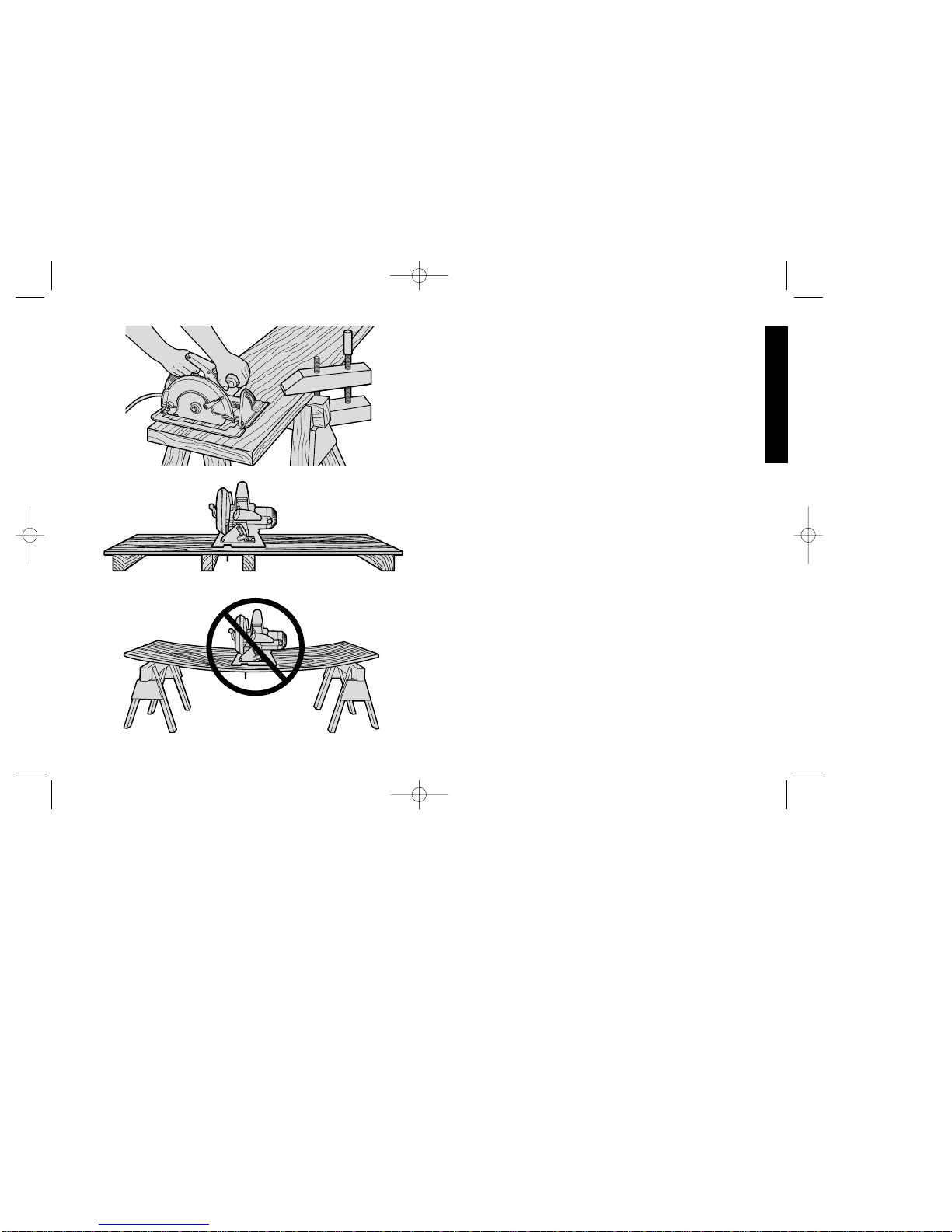
•SECURE WORK. Use clamps or a vise to hold work. It’s safer than
using your hand and it frees both hands to operate tool.
•DON’T OVERREACH. Keepproperfootingandbalanceatalltimes.
•MAINTAIN TOOLS WITH CARE. Keep tools sharp and clean for
betterandsaferperformance.Followinstructionsfor lubricating and
changing accessories. Inspect tool cords periodically and if
damaged, have repaired by authorized service facility. Inspect
extension cords periodically and replace if damaged. Keep handles
dry, clean, and free from oil and grease.
•DISCONNECT OR LOCK OFF TOOLS when not in use, before
servicing, and when changing accessories, such as blades, bits,
cutters.
•REMOVE ADJUSTING KEYS AND WRENCHES. Form habit of
checking to see that keys and adjusting wrenches are removed
from tool before turning it on.
•AVOID UNINTENTIONAL STARTING. Don’t carry tool with finger
1
English
on switch. Be sure switch is off when plugging in.
•EXTENSION CORDS. Make sure your extension cord is in good
condition. When using an extension cord, be sure to use one heavy
enough to carry the current your product will draw. An undersized
cord will cause a drop in line voltage resulting in loss of power and
overheating. The following table shows the correct size to use
depending on cord length and nameplate ampere rating. If in doubt,
use the next heavier gage. The smaller the gage number, the
heavier the cord.
Recommended Minimum Wire Size for Extension Cords
Total Length of Cord
25 ft. 50 ft. 75 ft. 100 ft. 125 ft. 150 ft. 175 ft.
7.6 m 15.2 m 22.9 m 30.5 m 38.1 m 45.7 m 53.3 m
Wire Size
18 AWG 18 AWG 16 AWG 16 AWG 14 AWG 14 AWG 12 AWG
•OUTDOOR USE EXTENSION CORDS. When tool is used
outdoors, use only extension cords intended for use outdoors and
so marked.
•STAY ALERT. Watch what you are doing. Use common sense.
Do not operate tool when you are tired.
•CHECK DAMAGED PARTS. Before further use of the tool, a
guard or other part that is damaged should be carefully checked
to determine that it will operate properly and perform its intended
function. Check for alignment of moving parts, binding of moving
parts, breakage of parts, mounting, and any other conditions that
may affect its operation. A guard or other part that is damaged
should be properly repaired or replaced by an authorized service
center unless otherwise indicated elsewhere in this instruction
manual. Have defective switches replaced by authorized service
center. Do not use tool if switch does not turn it on and off.
384102/DW359-220 5/2/02 3:14 PM Page 1

English
2
Additional Safety Instructions for Circular
Saws
•CAUTION: Whencuttingintowalls,floorsorwhereverliveelectrical
wires may be encountered, DO NOT TOUCH ANY METAL PARTS
OF THE TOOL! Hold the tool only by insulated grasping surfaces to
prevent electric shock if you cut in the live wire.
•KEEP GUARDS IN PLACE AND IN WORKING ORDER. Never
wedge or tie lower guard open. Check operation of lower guard
before each use. Do not use if lower guard does not close briskly
over saw blade. CAUTION: If saw is dropped, lower guard may be
bent, restricting full return.
•KEEP BLADES CLEAN AND SHARP. Sharp blades minimize
stalling and kickback.
•DANGER: KEEP HANDS AWAY FROM CUTTING AREA. Keep
hands away from blades. Do not reach underneath work while
blade is rotating. Do not attempt to remove cut material when blade
is moving. CAUTION: Blades coast after turn off.
•SUPPORT LARGE PANELS. Large panels must be supported as
shown in Figure16 to minimize the risk of blade pinching and
kickback. When cutting operation requires the resting of the saw on
the work piece, the saw shall be rested on the larger portion and the
smaller piece cut off.
•USE RIP FENCE. Always use a rip fence or straight edge guide
when ripping.
•GUARD AGAINST KICKBACK. Kickback occurs when the saw
stalls rapidly and is driven back towards the operator. Release
switch immediately if blade binds or saw stalls. Keep blades sharp.
Support large panels as shown in Figure 16. Use fence or straight
edge guide when ripping. Don’f force tool. Stay alert-exercise
control. Don’t remove saw from work during a cut while the blade is
moving.
•LOWER GUARD. Raise lower guard with the retracting handle.
•ADJUSTMENTS. Before cutting be sure depth and bevel
adjustments are tight.
•USE ONLY CORRECT BLADES IN MOUNTING. Do not use
blades with incorrect size holes. Never use defective or incorrect
blade washers or bolts.
•AVOID CUTTING NAILS. Inspect for and remove all nails from
lumber before cutting.
•CAUTION: Some wood contains preservatives such as copper
chromium arsenate (CCA) which can be toxic. When cutting these
materials extra care should be taken to avoid inhalation and
minimize skin contact.
SAVE THESE INSTRUCTIONS
Motor
Your DeWalt tool is powered by a DeWalt motor. Be sure your power
supply agrees with nameplate marking. 220 Volts AC/DC means your
saw will operate on alternating or direct current. Lower voltage can
cause loss of power and can result in overheating. All DeWalt tools are
factory-tested; if this tool does not operate, check the power supply.
Brushes
DISCONNECT PLUG FROM POWER SUPPLY BEFORE
SERVICING
Inspect carbon brushes regularly by unplugging tool, removing the
Brush Inspection Cap (Fig. 2) and withdrawing the brush assembly.
Keep brushes clean and sliding freely in their guides. Always replace
a used brush in the same orientation in the holder as it was prior to
removal. Carbon brushes have varying symbols stamped into their
sides, and if the brush is worn down to the line closest to the spring,
they must be replaced. Use only identical DeWalt brushes. Always
replace both brushes. Use of the correct grade of brush is essential
for proper operation. New brush assemblies are available at your
authorized service center. The tool should be allowed to “run in” (run
at no load without a blade) for 10 minutes before use to seat new
brushes.
384102/DW359-220 5/2/02 3:14 PM Page 2

While “running in” DO NOT TIE, TAPE, OR OTHERWISE LOCK THE
TRIGGER SWITCH ON. HOLD BY HAND ONLY.
Adjustments and Setup
ATTACHING AND REMOVING BLADES
DISCONNECT PLUG FROM POWER SUPPLY.
To attach the blade, retract lower blade guard and place inner clamp
washer and blade on saw spindle with printed side of blade out (teeth
at bottom of blade pointing forward) (FIG. 1.) Place outer clamp
washer on saw spindle. The larger surfaces of both washers must
face the blade. Thread on blade clamping screw firmly by hand to
hold both blade washers in position.
Lightly depress the blade lock (FIG. 2) while turning the spindle until
the blade stops rotating. Tighten blade clamping screw (clockwise)
firmly with the blade wrench (FIG. 3).
NEVER ENGAGE BLADE LOCK WHILE SAW IS RUNNING, OR
ENGAGE IN AN EFFORT TO STOP THE TOOL. NEVER TURN
SWITCH ON WHEN BLADE LOCK IS ENGAGED. SERIOUS
DAMAGE TO YOUR SAW WILL RESULT.
When removing the blade, first unplug the saw. Engage the blade
lock and unscrew the blade clamping screw by turning it counter-
clockwise with the blade wrench.
CUTTING DEPTH ADJUSTMENT
DISCONNECT PLUG FROM POWER SUPPLY.
Hold the saw firmly as shown in Figure 4. Loosen (counterclockwise)
the Depth Adjustment Lever and move shoe to obtain the desired
depth of cut, as shown in Figure 5. Make sure the Depth Adjustment
Lever has been retightened (clockwise) before operating saw.
Your saw is equipped with a carbide tipped saw blade for long life and
efficient cutting.
For the most efficient cutting action using a carbide tipped saw blade,
set the depth adjustment so that about one half of a tooth projects
below the surface of the wood to be cut. The height of a whole tooth
is the distance from the tip of the tooth to the bottom of the gullet in
3
English
FIG. 1 INNER
CLAMP
WASHER
OUTER
CLAMP
WASHER
BLADE CLAMPING SCREW
RETRACTING
LEVER
BLADE
LOCK
BRUSH
INSPECTION
CAP
FIG. 2
FIG. 3
TIGHTEN LOOSEN
384102/DW359-220 5/2/02 3:15 PM Page 3

4
front of it. Study Figures 5A and 5B to determine what one half tooth
means. (5A shows one half tooth projecting below the surface and
figure 5B shows a whole tooth projecting below the surface.)
Setting the saw at the proper cutting depth keeps blade friction to a
minimum, removes sawdust from between the blade teeth, results in
cooler, faster sawing and reduces the chance of kickback.
A method of checking for the correct cutting depth is shown in Figure
6. Lay a piece of the material you plan to cut along the side of the
blade, as shown in the figure, and observe how much tooth projects
beyond the material.
NOTE: When using a non carbide tipped blade, make an exception to
the above procedure and allow a full tooth to project below the
material, as shown in Figure 5B.
BEVEL ANGLE ADJUSTMENT
DISCONNECT THE SAW FROM THE POWER SUPPLY.
The full range of the Bevel Adjustment is from 0 TO 50 DEGREES.
The quadrant is graduated in increments of 5 degrees.
On the front of the saw is a bevel angle adjustment mechanism (Figure
8) consisting of a calibrated quadrant and a lever or knob. To set the
saw for a bevel cut, loosen (counterclockwise) the quadrant knob and
tilt shoe to the desired angle by aligning the pointer with the desired
angle mark. Retighten knob firmly (clockwise).
NOTE: The quadrant pointer, located between the quadrant knob and
the quadrant, can be adjusted after loosening its screw. Retighten
firmly after adjustment.
KERF INDICATOR
The front of the saw shoe has a kerf indicator (Figure 8) for vertical
and bevel cutting. This indicator enables you to guide the saw along
cutting lines penciled on the material being cut. The indicator lines up
with the left (inner) side of the saw blade, which makes the slot or
“kerf” cut by the moving blade fall to the right of the indicator. Guide
along the penciled cutting line so that the kerf falls into the waste or
surplus material – See Figure 9. Figure 9 shows the dimensions of the
shoe. The right dimension is 1-1/2” (standard 2x lumber).
English
FIG. 4
DEPTH
ADJUSTMENT
LEVER
FIG. 5
FIG. 6
GULLETSURFACE
OF WOOD
FIG. 7 RIP FENCE
TIP OF TOOTH
TIP OF TOOTH
FIG. 5A
FIG. 5B
GULLET
SURFACE
OF WOOD
384102/DW359-220 5/2/02 3:15 PM Page 4

SHOE ALIGNMENT
Your saw has been set at the factory for accurate vertical cuts (a 90
degree angle between the bottom of the shoe and the blade). The
edge of the shoe has also been set parallel to the blade so that it will
not bind when using an edge guide. If the saw should ever need
adjustment, it may be done as follows:
ADJUSTING FOR 90° CUTS
1. DISCONNECT PLUG FROM POWER SUPPLY.
2. Adjust the saw to 0° bevel.
3. Place saw on blade side (Fig. 10). Retract blade guard.
4. Loosen quadrant lever or knob (Fig. 10). Place a square against
the blade and shoe to adjust the 90° setting.
5. Loosen the hex nut and move the adjustment screw so that the
shoe will stop at the proper angle as shown in Figure 11. Lock
the screw in place by tightening the hex nut.
6. It may be necessary to adjust the quadrant angle pointer to line
up on “O” after shoe has been adjusted.
ADJUSTING THE SHOE PARALLEL TO THE BLADE
(Your saw is adjusted at the factory so that the blade and shoe are
parallel. If these parts become misaligned, adjust as follows.)
1. Disconnect plug from power supply.
2. Loosen the (2) screws at the adjusting bracket at the rear of the
shoe, as shown in Figure 12.
3. Adjust the shoe until it is parallel to the blade by measuring from
the edge of the shoe to the blade, front & rear. You can measure
from the outside edge of the blade to the shoe as shown in
Figure 12 or from the inner edge of the blade to the wider part
of the shoe. (Do not measure from the tips of any saw blade
teeth.)
4. When shoe is parallel, tighten all screws.
5
English
FIG. 8 QUADRANT
KERF
INDICATOR
45 0
123451
FIG. 9 GUIDE ALONG PENCILED
CUTTING LINE SO KERF
FALLS IN WASTE STOCK
DIRECTION OF CUT
KERF
QUADRANT
KNOB
WASTE OR
SURPLUS STOCK
Align left side of
saw blade
with“45” mark, as
shown, for 45°
bevel cutting
5 " 1-1/2"
Align left side of
saw blade with
“0” mark for
straight cutting
QUADRANT KNOB
FIG. 10
DESIRED WIDTH
OF STOCK
CORD
KEEPER
384102/DW359-220 5/2/02 3:15 PM Page 5

6
ADJUSTING DEPTH ADJUSTMENT LEVER
It may be desirable to adjust the Depth Adjustment. (It will sometimes
hit the shoe before tightening or loosening completely.)
To adjust lever, follow the steps below.
1. Disconnect plug from power supply.
2. Using a small screwdriver, pry the lock ring off, as shown in Figure
13.
3. Remove the lever and rotate it in the desired direction about 1/8
revolution. (More or less as necessary.)
4. Reinstall the lever and insert the lock ring with concave side
against lever to hold it in place. (Figure 14)
Operation
SWITCH
Pull the trigger switch to turn the motor “ON”. Releasing the trigger
turns the motor “OFF”. This tool has no provision to lock the switch
in the “ON” position, and should never be locked “ON” in any way.
WORKPIECE SUPPORT
Figure 15 shows proper sawing position. Note that hands are kept
away from cutting area, and power cord is positioned clear of the
cutting area so that it will not get caught or hung up on the work.
To avoid kickback, DO support board or panel NEAR the cut, (Figure
16). DON’T support board or panel away from the cut (Figure 17).
When operating the saw, keep the cord away from the cutting area
and prevent it from becoming hung up on the work piece. Note that
a special Cord Keeper has been provided on the tool’s handle. (See
Fig. 10 on page 6.) Press the cord firmly into the cord keeper to keep
it out of the way but in sight so you know where it is at all times.
WARNING: It is important to support the work properly and to hold
the saw firmly to prevent loss of control which could cause personal
injury; Figure 18 illustrates typical hand support of the saw.
English
FIG. 12
SCREWS
FIG. 13 FIG. 14
LOCK
NUT
LOCK
RING LEVER TIGHTEN
LOOSEN
FIG. 11
SCREWS
QUADRANT
KNOB
ADJUSTMENT SCREW
384102/DW359-220 5/2/02 3:15 PM Page 6

ALWAYS DISCONNECT SAW BEFORE MAKING ANY
ADJUSTMENTS! Place the work with its “good” side – the one on
which appearance is most important – down. The saw cuts upward,
so any splintering will be on the work face that is up when you saw it.
CUTTING
Support the work so that the cut will be on your right. Place the wider
portion of the saw shoe on that part of the work piece which is solidly
supported, not on the section that will fall off when the cut is made.
As examples, Figure 18 illustrates the RIGHT way to cut off the end
of a board, and Figure 19 the WRONG way. Always clamp work.
Don’t try to hold short pieces by hand! Remember to support
cantilevered and overhanging material. Use caution when sawing
material from below.
Be sure saw is up to full speed before blade contacts material to be
cut. Starting saw with blade against material to be cut or pushed
forward into kerf can result in kickback.
Push the saw forward at a speed which allows the blade to cut
without laboring. Hardness and toughness can vary even in the same
piece of material, and knotty or damp sections can put a heavy load
on the saw. When this happens, push the saw more slowly, but hard
enough to keep it working without much decrease in speed.
Forcing the saw can cause rough cuts, inaccuracy, kickback and
over-heating of the motor.
Should your cut begin to go off the line, don’t try to force it back on.
Release the switch and allow blade to come to a complete stop. Then
you can withdraw the saw, sight anew, and start a new cut slightly
inside the wrong one. In any event, withdraw the saw if you must shift
the cut. Forcing a correction inside the cut can stall the saw and lead
to kickback. IF SAW STALLS, RELEASE THE TRIGGER AND BACK
THE SAW UNTIL IT IS LOOSE. BE SURE BLADE IS STRAIGHT IN
THE CUT AND CLEAR OF THE EDGE BEFORE RESTARTING.
As you finish a cut, release the trigger and allow the blade to stop
before lifting the saw from the work. As you lift the saw, the spring-
7
English
FIG. 15
FIG. 16
SUPPORT WORK
NEAR CUT
FIG. 17
WRONG -
MATERIAL BENDS ON
BLADE CAUSING HEAVY
LOADS OR KICKBACK.
RIGHT
384102/DW359-220 5/2/02 3:15 PM Page 7

8
exist.
1. IMPROPER WORKPIECE SUPPORT
A. Sagging or improper lifting of the cut off piece causing
pinching of the blade.
B. Cutting through material supported at the outer ends only
(see Figure 17). As the material weakens it sags, closing
down the kerf and pinching the blade.
C. Cutting off a cantilevered or overhanging piece of material
from the bottom up in a vertical direction. The falling cut off
piece can pinch the blade.
D. Cutting off long narrow strips (as in ripping). The cut off strip
can sag or twist closing the kerf and pinching the blade.
E. Snagging the lower guard on a surface below the material
beingcut momentarily reducing operator control. The saw can
lift partially out of the cut increasing the chance of blade twist.
2. IMPROPER DEPTH OF CUT SETTING ON SAW
Using the saw with an excessive depth of cut setting increases
loading on the unit and susceptibility to twisting of the blade in
the kerf. It also increases the surface area of the blade avaliable
for pinching under conditions of kerf close down.
English
tensioned telescoping guard will automatically close under the blade.
Remember the blade is exposed until this occurs, never reach under
the work for any reason whatsoever. When you have to retract the
telescoping guard manually (as is necessary for starting pocket cuts)
always use the retracting lever.
NOTE: When cutting thin strips, be careful to ensure that small cutoff
pieces don’t hang up on inside of lower guard.
When ripping (cutting with the grain) the use of a rip fence is
recommended. (See Figure 7)
POCKET CUTTING
DISCONNECT PLUG FROM POWER SUPPLY WHEN MAKING
THIS OR ANY OTHER ADJUSTMENT. Adjust saw shoe so blade
cuts at desired depth. Tilt saw forward and rest front of the shoe on
material to be cut. Using the retracting lever, retract blade guard to an
upward position. Lower rear of shoe until blade teeth almost touch
cutting line. Now release the blade guard (its contact with the work
will keep it in position to open freely as you start the cut) (Figure 20).
Start the motor and gradually lower the saw until its shoe rests flat on
the material to be cut. Advance saw along the cutting line until cut is
completed. Release trigger and allow blade to stop completely before
withdrawing the blade from the material. When starting each new cut,
repeat as above. Never tie the blade guard in a raised position.
Kickback
When the saw blade becomes pinched or twisted in the cut, kickback
can occur. The saw is thrust rapidly back toward the operator. When
the blade is pinched or bound tightly by the kerf closing down, the
blade stalls and the motor reaction drives the unit backward. When
the blade becomes twisted or misaligned in the cut, the teeth at the
back edge of the blade can dig into the top surface of the wood
causing the blade to climb out of the kerf and jump back toward the
operator.
Kickback is more likely to occur when any of the following conditions
FIG. 18 FIG. 19
WRONG
384102/DW359-220 5/2/02 3:15 PM Page 8

3. BLADE TWISTING (MIS-
ALIGNMENT IN CUT)
A. Pushing harder to cut
througha knot, a nail, or
a hard grain area can
cause the blade to
twist.
B. Trying to turn the saw in
the cut (trying to get
back on the marked
line) can cause blade
twist.
C. Extended reach or operating saw with poor body control (out
of balance), can result in twisting the blade.
D. Changing hand grip or body position while cutting can result
in blade twist.
E. Backing unit up to clear blade can lead to twist if not done
carefully.
4. MATERIALS THAT REQUIRE EXTRA ATTENTION
A. Wet lumber
B. Green lumber (material freshly cut or not kiln dried)
C. Pressure treated lumber (material treated with preservatives
or anti-rot chemicals)
5. USE OF DULL OR DIRTY BLADES
Dull blades cause increased loading of the saw. To
compensate, an operator will usually push harder which further
loads the unit and promotes twisting of the blade in the kerf.
Worn blades may also have insufficient body clearance which
increases the chance of binding and increased loading.
6. LIFTING THE SAW WHEN MAKING BEVEL CUTS
Bevel cuts require special operator attention to proper cutting
techniques – especially guidance of the saw. Both blade angle
to the shoe and greater blade surface in the material increase
the chance for binding and misalignment (twist) to occur.
7. RESTARTING A CUT WITH THE BLADE TEETH JAMMED
AGAINST THE MATERIAL
The saw should be brought up to full operating speed before
starting a cut or restarting a cut after the unit has been stopped
with the blade in the kerf. Failure to do so can cause stalling
and kickback.
Any other conditions which could result in pinching, binding, twisting,
or misalignment of the blade could cause kickback. Refer to the
sections on “Adjustments And Set-Up” and “Operation” for
procedures and techniques that will minimize the occurrence of
kickback.
Blades
A dull blade will cause slow, inefficient cutting, overload on the saw
motor, excessive splintering and increase the possibility of kickback.
It is a good practice to keep extra blades on hand so that sharp
blades are available while the dull ones are being sharpened (See
“SAWS-SHARPENING” in the Yellow Pages). In fact, many lower
priced blades can be replaced with new ones at very little cost over
the sharpening price.
Hardened gum on the blade will slow down the cutting. This gum
can best be removed with trichlorethylene, kerosene, turpentine or
oven cleaner.
DeWalt manufactures a complete line of 7-1/4” (180mm) diameter
saw blades and they are available from your authorized service
center.
VISUALLY EXAMINE CARBIDE BLADES BEFORE USE.
REPLACE IF DAMAGED.
Accessories
Recommended accessories for use with your tool are available at
extra cost from your local service center. A complete listing of service
centers is included with your tool.
9
English
FIG. 20
384102/DW359-220 5/2/02 3:15 PM Page 9

Full Warranty
DEWALT heavy duty industrial tools are warranted for one year from
date of purchase. We will repair, without charge, any defects due to
faulty materials or workmanship. For warranty repair information,
call 1-800-4-DEWALT. This warranty does not apply to accessories or
damage caused where repairs have been made or attempted by
others. This warranty gives you specific legal rights and you may
have other rights which vary in certain states or provinces.
In addition to the warranty, DEWALT tools are covered by our:
30 DAY NO RISK SATISFACTION GUARANTEE
If you are not completely satisfied with the performance of your
DEWALT heavy duty industrial tool, simply return it to the participating
seller within 30 days for a full refund. Please return the complete unit,
transportation prepaid. Proof of purchase may be required.
10
If you need any assistance in locating any accessory, please contact
DeWalt Industrial Tool Company, P.O. Box 158, 626 Hanover Pike,
Hampstead MD 21074 or call 1-800-732-4441.
A. RIP FENCE: Attaches to top of saw shoe. Permits rip cuts without
penciled guide line.
B. SAW PROTRACTOR: Guides saw for accurate cut-off work.
Adjusts from 0 to 70 degrees.
C. CUT-OFF GUIDE: For 90 degree or 45 degree cuts.
CAUTION: Recommended accessories and saw blades for your
saw are listed in this manual. The use of any other accessory or
attachment may be hazardous.
Cleaning and Lubrication
Use only mild soap and a damp cloth to clean the tool. Never let any
liquid get inside the tool; never immerse any part of the tool into a
liquid.
Accesories
Recommended accessories for use with your tool are available at
estra cost from your distributor or authorized service center.
CAUTION: The use of any non-recommended accessory may be
hazardousl.
Important!
To assure product SAFETY and RELIABILITY, repairs, maintenance
and adjustment (including brush inspection and replacement) should
be performed by authorized service centers or other qualified service
organizations, always using identical replacement parts
English
384102/DW359-220 5/2/02 3:15 PM Page 10

11
Français
POUR TOUT RENSEIGNEMENT SUPPLÉMENTAIRE SUR CET
OUTIL OU TOUT AUTRE OUTIL DEWALT, COMPOSER SANS
FRAIS LE NUMÉR SUIVANT.
1 800 4-DEWALT (1 800 433-9258)
Importantes mesures de sécurité
AVERTISSEMENT : Afin de réduire les risques d’incendie, de
secousses électriques ou de blessures lorsqu’on utilise des outils
électriques, il faut toujours respecter les mesures de sécurité
suivantes.
LIRE TOUTES LES DIRECTIVES.
Mise à la terre
L’outil devrait être mis à la terre lorsqu’on
s’en sert afin de protéger l’utilisateur contre
les secousses électriques. Le conducteur
vert (ou vert et jaune) du cordon sert de
mise à la terre. Ne jamais relier le
conducteur vert (ou vert et jaune) à une
borne sous tension.
Il faut relier les deux contacts de mise à la
terre et la fiche de mise à la terre à une
mise à la terre permanente, comme une prise bien mise à la terreIl
n’existe aucun adaptateur pour une fiche semblable à celle illustrée
à la figure A.
Mesures de sécurité pour tous les outils
•BIEN DÉGAGER LA SURFACE DE TRAVAIL. Des surfaces et
des établis encombrés peuvent être la cause de blessures.
•TENIR COMPTE DU MILIEU DE TRAVAIL. Protéger les outils
électriques de la pluie. Ne pas s’en servir dans des endroits
humides ou mouillés. Bien éclairer la surface de travail. Ne pas se
servir de l’outil en présence de liquides ou de vapeurs
inflammables.
•SE PROTÉGER CONTRE LES SECOUSSES ÉLECTRIQUES.
Éviter tout contact avec des objets mis à la terre, comme des
tuyaux, radiateurs, cuisinières, réfrigérateurs et autres objets du
genre.
INTERRUPTEUR
À DÉTENTE
RESSORT DE
RAPPEL
PROTÈGE-LAME INFÉRIEUR
PATIN
BOUTON OU LEVIER
DU SECTEUR
SECTEUR
A
384102/DW359-220 5/2/02 3:15 PM Page 11

12
Français
•ÉLOIGNER LES ENFANTS. Tous les visiteurs doivent être tenus
à l’écart de l’aire de travail et il faut les empêcher de toucher à
l’outil ou au cordon de rallonge.
•RANGER LES OUTILS INUTILISÉS. Il faut ranger les outils dans
un endroit sec, situé en hauteur ou fermé à clé, hors de la portée
des enfants.
•NE JAMAIS FORCER L’OUTIL. Afin d’obtenir un rendement sûr
et efficace, utiliser l’outil à son rendement nominal.
•UTILISER L’OUTIL APPROPRIÉ. Ne jamais exiger d’un petit outil
ou d’un accessoire le rendement d’un outil de fabrication plus
robuste. Se servir de l’outil selon l’usage prévu.
•PORTER DES VÊTEMENTS APPROPRIÉS. Éviter de porter des
vêtements amples et des bijoux qui peuvent être happés par les
pièces en mouvement. Porter des gants de caoutchouc et des
chaussures à semelle antidérapante pour travailler à l’extérieur.
Protéger la chevelure si elle est longue.
•PORTER DES LUNETTES DE SÉCURITÉ. Porter également un
masque respiratoire si le travail de coupe produit de la poussière.
•NE PAS MANIPULER LE CORDON DE FAÇON ABUSIVE. Ne
pas transporter l’outil par le cordon ni tirer sur ce dernier pour le
débrancher de la prise. Éloigner le cordon des sources de chaleur,
des flaques d’huile et des arêtes tranchantes.
•ASSUJETTIR LA PIÈCE. Immobiliser la pièce à l’aide de brides
ou d’un étau. On peut alors se servir des deux mains pour faire
fonctionner l’outil, ce qui est plus sûr.
•NE PAS DÉPASSER SA PORTÉE. Toujours demeurer dans une
position stable et garder son équilibre.
•PRENDRE SOIN DES OUTILS. Conserver les outils propres pour
qu’ils donnent un rendement supérieur et sûr. Suivre les directives
concernant la lubrification et le remplacement des accessoires.
Inspecter régulièrement le cordon de l’outil et le faire réparer au
besoin à un atelier d’entretien autorisé. Inspecter régulièrement les
cordons de rallonge et les remplacer lorsqu’ils sont endommagés.
S’assurer que les poignées sont toujours propres, sèches et libres
de toute tache d’huile ou de graisse.
•DÉBRANCHER OU VERROUILLER EN POSITION HORS
TENSION LES OUTILS NON UTILISÉS. Respecter cette mesure
lorsqu’on ne se sert pas de l’outil, ou qu’on doit le réparer ou en
changer un accessoire (comme une lame, un foret ou un couteau).
•ENLEVER LES CLÉS DE RÉGLAGE. Prendre l’habitude de
vérifier si les clés de réglage ont été retirées avant de faire
démarrer l’outil.
•ÉVITER LES DÉMARRAGES ACCIDENTELS. Ne pas laisser le
doigt sur l’interrupteur lorsqu’on transporte l’outil. S’assurer que
l’interrupteur est à la position hors circuit lorsqu’on branche l’outil.
•CORDONS DE RALLONGE. S’assurer que le cordon de rallonge
est en bon état. Lorsqu’on se sert d’un cordon de rallonge,
s’assurer qu’il est de calibre approprié pour la tension nécessaire
au fonctionnement de l’outil. L’utilisation d’un cordon de calibre
inférieur occasionne une baisse de tension entraînant une perte de
puissance et la surchauffe. Le tableau suivant indique le calibre
approprié selon la longueur du cordon et les mentions de la plaque
signalétique de l’outil. En cas de doute, utiliser un cordon de calibre
supérieur. Le chiffre indiquant le calibre est inversement
proportionnel au calibre du cordon.
Calibre minimal des cordons de rallonge
Longueur totale du cordon
25 ft. 50 ft. 75 ft. 100 ft. 125 ft. 150 ft. 175 ft.
7.6 m 15.2 m 22.9 m 30.5 m 38.1 m 45.7 m 53.3 m
Intensité
18 AWG 18 AWG 16 AWG 16 AWG 14 AWG 14 AWG 12 AWG
•CORDONS DE RALLONGE PRÉVUS POUR L’EXTÉRIEUR.
Lorsque l’outil est utilisé à l’extérieur, ne se servir que d’un cordon
de rallonge conçu pour l’extérieur et portant la mention appropriée.
•DEMEURER VIGILANT. Travailler avec vigilance et faire preuve
de bon sens. Ne pas se servir de l’outil lorsqu’on est fatigué.
•VÉRIFIER LES PIÈCES ENDOMMAGÉES. Avant de continuer à
384102/DW359-220 5/2/02 3:15 PM Page 12

utiliser l’outil, il faut vérifier si le protecteur ou toute autre pièce
endommagée remplit bien la fonction pour laquelle il a été prévu.
Vérifier l’alignement et les attaches des pièces mobiles, le degré
d’usure des pièces et leur montage, ainsi que tout autre facteur
susceptible de nuire au bon fonctionnement de l’outil. Faire réparer
ou remplacer tout protecteur ou toute autre pièce endommagée
dans un centre de service autorisé, sauf si le présent guide fait
mention d’un avis contraire. Confier le remplacement de tout
interrupteur défectueux à un centre de service autorisé. Ne jamais
se servir d’un outil dont l’interrupteur est défectueux.
Mesures de sécurité additionnelles
relatives aux scies circulaires
•MISE EN GARDE : Lorsqu’on coupe dans les murs, les planchers
ou tout autre endroit où peuvent se trouver des fils sous tension,
NE PAS TOUCHER AUX COMPOSANTS MÉTALLIQUES DE
L’OUTIL. Ne le saisir que par ses surfaces en plastique afin de se
protéger des secousses électriques si on entre en contact avec
un fil sous tension.
•S’ASSURER QUE LES PROTECTEURS EN PLACE ET EN
ÉTAT DE FONCTIONNEMENT. Ne jamais bloquer ni attacher le
protecteur inférieur en position ouverte. Vérifier le fonctionnement
du protecteur inférieur avant chaque utilisation. Ne pas e servir de
l’outil lorsque le protecteur inférieur ne se ferme pas complètement
sur la lame. MISE EN GARDE : Si la scie tombe, le protecteur
inférieur peut se tordre et ne plus se refermer complètement.
•S’ASSURER QUE LES LAMES SONT PROPRES ET
AFFÛTÉES. Des lames affûtées minimisent les risques de calage
et de rebond.
•DANGER : ÉLOIGNER LES MAINS DE LA ZONE DE COUPE.
Éloigner les mains de la lame. Ne pas placer les mains sous la
pièce à découper pendant les travaux lorsque la lame tourne. Ne
pas tenter de retirer du matériau lorsque la lame est en
mouvement. MISE EN GARDE : La lame continue de tourner
après la mise hors tension.
•SOUTENIR LES GRANDS PANNEAUX. Il faut soutenir les
panneaux de grandes dimensions de la façon illustrée à la figure
16 afin de minimiser les risques de coincement de la lame et de
rebond. Lorsqu’il faut déposer la scie contre la pièce à découper
pendant les travaux, il faut la déposer sur la partie la plus large du
matériau et découper la plus petite partie.
•UTILISER UN GUIDE DE REFENTE. Toujours utiliser un guide
de refente ou un guide à rebord droit lors des coupes en refente.
•SE PROTÉGER CONTRE LES RISQUES DE REBOND. Le
rebond se produit lorsque la lame se bloque rapidement et qu’elle
ressort du matériau vers l’utilisateur. Il faut relâcher
immédiatement l’interrupteur en cas de blocage ou de calage.
Maintenir les lames bien affûtées. Soutenir les panneaux de
grandes dimensions de la façon illustrée à la figure 16. Utiliser un
guide de refente ou à rebord droit lors des coupes en refente. Ne
pas forcer l’outil. Rester vigilant; maîtriser la situation. Ne pas
retirer la scie du matériau lorsque la scie est en mouvement.
•PROTECTEUR INFÉRIEUR. Utiliser le ressort de rappel pour
soulever le protecteur inférieur.
•RÉGLAGES. S’assurer que les réglages de coupe en biseau et de
profondeur sont bien serrés avant la coupe.
•LORS DU MONTAGE, UTILISER SEULEMENT DES LAMES
APPROPRIÉES. Ne pas utiliser une lame dont le diamètre du trou
n’est pas approprié. Ne jamais utiliser des rondelles ou des
boulons de lames défectueux ou de dimensions inappropriées.
•ÉVITER DE COUPER DES CLOUS. Examiner la pièce à
découper pour s’assurer qu’elle ne renferme aucun clou avant les
travaux. Le cas échéant, les retirer.
•MISE EN GARDE : Certaines essences de bois renferment des
agents de conservation (comme de l’arséniate de cuivre et de
chrome) qui peuvent être toxiques. Lorsqu’on doit couper de tels
matériaux, prendre des mesures supplémentaires afin d’éviter
d’inhaler les vapeurs toxiques et de minimiser les contacts avec la
peau.
13
Français
384102/DW359-220 5/2/02 3:15 PM Page 13

14
CONSERVER CES MESURES.
Moteur
Un moteur DeWalt entraîne l’outil DeWalt. Veiller à ce que la tension
d’alimentation soit conforme aux exigences de la plaque signalétique
de l’outil. La mention 220 volts c.a./c.c. signifie que l’outil fonctionne
également sur une alimentation en courant alternatif ou continu.
Une baisse de tension entraîne une perte de puissance et la
surchauffe. Tous les outils DeWalt sont essayés avant de quitter
l’usine. Lorsque celui-ci refuse de fonctionner, vérifier la source de
courant électrique.
Balais
DÉBRANCHER L’OUTIL AVANT D’EN FAIRE L’ENTRETIEN.
Inspecter régulièrement les balais en charbon en débranchant
d’abord la scie, en retirant le couvercle d’inspection des balais (fig. 2)
et en sortant l’assemblage-balais. S’assurer que les balais sont
propres et qu’ils glissent bien dans leurs guides. Toujours remplacer
les balais usés par des balais placés dans le même sens dans le
porte-balai. Différents symboles sont inscrits sur les côtés des balais
en charbon. Lorsque le balai est usé jusqu’à la ligne la plus près du
ressort, il faut le remplacer. N’utiliser que des balais de rechange
identiques DeWalt. Il faut toujours remplacer les deux balais. Il faut
utiliser des balais de même qualité pour s’assurer du bon
fonctionnement du frein électrique (dans le cas des modèles qui en
sont pourvus). Le centre de service de la région vend des balais de
rechange. Il faut laisser l’outil fonctionner à vide (sans charge et sans
lame) pendant dix minutes avant de l’utiliser afin de permettre aux
nouveaux balais de s’installer. Cette mesure est des plus importantes
car les scies dotées de freins électriques peuvent fonctionner de
façon irrégulière jusqu’à ce que les balais se placent.
Pendant le fonctionnement à vide de la scie, NE PAS ATTACHER,
COLLER NI BLOQUER DE TOUTE AUTRE FAÇON
L’INTERRUPTEUR À DÉTENTE. LE TENIR À LA MAIN
SEULEMENT.
Réglage et installation
INSTALLATION ET RETRAIT DE LA LAME
DÉBRANCHER LA SCIE.
Pour installer la lame, escamoter le protège-lame inférieur et placer
la rondelle de fixation interne et la lame sur l’arbre de la scie en
plaçant la face imprimée de la lame vers l’extérieur (les dents au
bas de la lame pointant vers l’avant) (fig. 1). Installer la rondelle de
fixation externe de la lame sur l’arbre de la scie. Les surfaces larges
des deux rondelles doivent se trouver sur la lame. Serrer fermement
à la main la vis de fixation de la lame de manière à retenir les deux
rondelles en place.
Enfoncer légèrement le dispositif de verrouillage de la lame (fig. 2) en
faisant tourner l’arbre jusqu’à ce que la lame s’immobilise. Serrer
fermement (dans le sens horaire) la vis de fixation de la lame avec
la clé de la scie (fig. 3).
NE JAMAIS ENGAGER LE DISPOSITIF DE VERROUILLAGE DE
LA LAME LORSQUE LA SCIE FONCTIONNE NI POUR
IMMOBILISER L’OUTIL. NE JAMAIS METTRE LA SCIE EN
MARCHE LORSQUE LE DISPOSITIF DE VERROUILLAGE DE LA
LAME EST EN PLACE, AU RISQUE DE GRAVEMENT
ENDOMMAGER LA SCIE.
Pour retirer la lame, débrancher tout d’abord la scie. Mettre le
dispositif de verrouillage de la lame en place et desserrer la vis de
fixation de la lame en la faisant tourner dans le sens antihoraire à
l’aide de la clé de la lame.
Français
384102/DW359-220 5/2/02 3:15 PM Page 14

RÉGLAGE DE LA PROFONDEUR DE COUPE
DÉBRANCHER LA SCIE.
Saisir fermement la scie comme le montre la figure 4. Desserrer
(dans le sens antihoraire) le levier de réglage de la profondeur de
coupe et déplacer le patin de façon à obtenir la profondeur de coupe
voulue, illustré à la figure 5. Bien resserrer (dans le sens horaire) le
levier de réglage de la profondeur de coupe avant de se servir de la
scie.
La scie est munie d’une lame à dents au carbure qui en prolongent la
durée et en rend la coupe des plus efficaces.
Pour optimiser les résultats de coupe lorsqu’on utilise une lame à
dents au carbure, régler la profondeur de coupe de sorte qu’une
moitié de dent de la lame sorte du dessous du matériau à découper.
La hauteur de la dent correspond à la distance à partir du bout de la
dent jusqu’au fond du creux en forme d’hameçon situé devant la
dent. Bien examiner les figures 5A et 5B afin de déterminer à quoi
correspond une moitié de dent. (La figure 5A montre une moitié de
dent sortant du dessous du matériau et la figure 5B montre toute une
dent sortant du dessous du matériau.)
Cette mesure minimise la friction de la lame, permet l’évacuation de
la sciure, assure une coupe rapide et en douceur tout en réduisant
les risques de rebond.
La figure 6 illustre la marche à suivre pour vérifier le réglage de la
profondeur. Déposer un échantillon du matériau à découper le long
de la lame. Remarquer comment la dent de la lame sort de
l’échantillon.
NOTE : Lorsqu’on utilise une lame dont les dents ne sont pas au
carbure, ne pas se conformer aux directives précédentes et faire
sortir la dent au complet du matériau à découper (fig. 5B).
RÉGLAGE POUR COUPES EN BISEAU
DÉBRANCHER LA SCIE.
La gamme complète de réglage pour les coupes en biseau va de
0 À 50 DEGRÉS. Le secteur est calibré en multiples de 5 degrés.
15
Français
FIG. 1
RONDELLE
DE FIXATION
INTERNE
RONDELLE
DE FIXATION
EXTERNE
VIS DE FIXATION DE LA LAME
RESSORT DE
RAPPEL
DISPOSITIF DE
VERROUILLAGE
DE LA LAME
COUVERCLE
D’INSPECTION
DES BALAIS
FIG. 2
FIG. 3
SERRER DESSERRER
384102/DW359-220 5/2/02 3:15 PM Page 15

16
Français
FIG. 4
LEVIER DE
RÉGLAGE DE LA
PROFONDEUR
FIG. 5
FIG. 6
SURFACE
DU BOIS
FIG. 7
GUIDE DE REFENTE
BOUT DE LA DENT BOUT DE LA DENT
FIG. 5A FIG. 5B
CREUX EN FORME
D’HAMEÇON SURFACE
DU BOIS
Le mécanisme de réglage de l’angle de coupe se trouve à l’avant de la
scie (figure 8) et il consiste en un secteur calibré et en un levier ou un
bouton. Le réglage de la scie pour les coupes en biseau se fait en
desserrant (dans le sens antihoraire) le levier ou le bouton du secteur,
et en faisant basculer le patin jusqu’à ce qu’on obtienne l’angle voulu
en alignant l’indicateur sur l’angle indiqué. Resserrer fermement (dans
le sens horaire) le levier ou le bouton.
NOTE : L’indicateur qui se trouve entre le levier ou le bouton et le
secteur peut être réglé en desserrant sa vis. Bien la resserrer après le
réglage.
INDICATEUR DE VOIE
À l’avant du patin de la scie, il y a un indicateur de voie (fig. 8) servant
aux coupes à la verticale et en biseau. L’indicateur permet de guider la
scie le long de lignes de coupe tracées sur le matériau à découper.
L’indicateur s’aligne sur le côté gauche (interne) de la lame de la scie
permettant à la lame de couper la voie à droite de l’indicateur. Guider
lasciele long de la ligne de coupe tracée de sorte que la voie se trouve
du côté du surplus de matériau (voir la figure 9). La figure 9 montre les
dimensions du patin.Le côté droit mesure 38 mm (1 1/2 po) (mesure
standard d’une pièce de bois de 2 po sur x 2 po).
RÉGLAGE DU PATIN
La scie est réglée à l’usine pour assurer la précision des coupes
verticales (angle de 90° entre le dessous du patin et la lame). Le
rebord du patin est également réglé de façon à être parallèle à la lame
afin que celle-ci ne bloque pas lorsqu’on utilise un guide. Dans le cas
peu probable où il faudrait régler la scie, voici la marche à suivre.
RÉGLAGE POUR COUPES À 90°
1. Débrancher la scie.
2. Régler la scie à la mention 0°.
3. Placer la scie sur le côté (fig. 10). Escamoter le protège-lame.
4. Desserrer le levier ou le bouton du secteur (fig. 10). Placer une
équerre contre la lame et le patin afin de régler l’angle à 90°.
5. Desserrer l’écrou hexagonal et déplacer la vis de réglage de
384102/DW359-220 5/2/02 3:15 PM Page 16

45 0
123451
manière à ce que le patin s’arrête à l’angle voulu, comme le montre
la figure 11. Bloquer la vis en place en resserrant l’écrou
hexagonal.
6. Il peut être nécessaire de régler l’indicateur du secteur de manière
à l’aligner sur la mention «0» après avoir réglé le patin.
RÉGLAGE DU PATIN PARALLÉLE À LA LAME
(La scie est réglée en usine de sorte que la lame soit parallèle au patin.
Si l’alignement de ces composantes se défait, le régler comme suit.)
1. Débrancher la scie.
2. Desserrer les deux vis de la bride de réglage à l’arrière du patin,
comme le montre la figure 12.
3. Régler le patin jusqu’à ce qu’il soit parallèle à la lame en mesurant
à partir du rebord du patin jusqu’à la lame (à l’avant et à l’arrière).
On peut mesurer à partir de la partie extérieure de la lame jusqu’au
patin (illustré à la figure 12) ou de la partie intérieure de la lame
jusqu’à la partie large du patin. (Ne jamais mesurer à partir du bout
d’une dent de la lame.)
4. Lorsque le patin est parallèle à la lame, resserrer toutes les vis.
RÉGLAGE DE BOUTONS DU RÉGLAGE DE LA PROFONDEUR
DE COUPE ET DU SECTEUR
Onpeutvouloir régler le boutons de réglage de la profondeur de coupe
ou du secteur. (Ceux-ci peuvent parfois frapper contre le patin
lorsqu’ils ne sont pas complètement serrés ou desserrés.) Pour régler
l’un ou l’autre, se conformer aux étapes suivantes.
1. Débrancher la scie.
2. Au moyen d’un petit tournevis, soulever la bague de blocage,
comme le montre la figure 13.
3. Retirer le levier et le faire tourner dans le sens voulu d’environ
1/8 de tour. (Plus ou moins, au besoin.)
4. Réinstaller le levier et insérer la bague de blocage en plaçant le
côté concave contre le levier pour le retenir en place (fig. 14).
17
Français
FIG. 8
SECTEUR
INDICATEUR
DE VOIE
FIG. 9 GUIDER LE LONG DE LA
LIGNE TRACÉE DE SORTE
QUE LA VOIE SE TROUVE
DANS LE SURPLUS DE
MATÉRIAU.
SENS DE COUPE
VOIE
BOUTON OU LEVIER
DU SECTEUR
SURPLUS DE
MATÉRIAU
Aligner le côté
gauche de la lame
sur la mention
«45», comme
illustré, pour couper
à un angle de 45°.
5 po 1 1/2 po
Aligner le côté
gauche de la lame
sur la mention «0»
pour couper en ligne
droite.
BOUTON OU
LEVIER DU
SECTEUR
FIG. 10
LARGEUR VOULUE
DE MATÉRIAU
SERRE-FIL
384102/DW359-220 5/2/02 3:15 PM Page 17
Table of contents
Languages:
Other DeWalt Saw manuals

DeWalt
DeWalt DCS579X2 User manual

DeWalt
DeWalt DW718 User manual

DeWalt
DeWalt DCS391B User manual

DeWalt
DeWalt DW718 User manual

DeWalt
DeWalt DW367 User manual

DeWalt
DeWalt DCS781 User manual

DeWalt
DeWalt D23700 User manual

DeWalt
DeWalt DWS716XPS User manual

DeWalt
DeWalt D23620 User manual

DeWalt
DeWalt DWE7485 User manual

DeWalt
DeWalt D28715 User manual

DeWalt
DeWalt DW704 User manual

DeWalt
DeWalt XR Li-ION DCS335 User manual

DeWalt
DeWalt DW745 User manual

DeWalt
DeWalt DWE550 User manual

DeWalt
DeWalt D27111 User manual

DeWalt
DeWalt DW303M User manual

DeWalt
DeWalt DWM120 User manual

DeWalt
DeWalt D28710-XE User manual

DeWalt
DeWalt DCM200 User manual