dewert okin ECO BETADRIVE ECO Series User manual

ECO BETADRIVE ECO
Installation Instructions
(Translation of the original installation instructions)


ECO BETADRIVE ECO Foreword
81417 3.0 3
Foreword
Document revision history
Version
Date
Modification, change
1.0
03/2015
2.0
04/2018
Fixing screws defined
3.0
07/2019
Ratings plate, disposal, graphics
(insatallation), technical specifi-
cations,
Disclaimer and exclusion of liability
DewertOkin is not responsible for damage resulting from:
failure to observe these instructions,
changes made to this product which have not been approved by DewertOkin, or
the use of replacement parts which have not been approved or manufactured by DewertOkin.
We reserve the right to make unannounced technical changes in the course of our continual prod-
uct improvement process!
Creation of a complete operating instruction manual for the entire end product
These instructions are only intended to be used by the end-product manufacturer. They should not
be given to the operator of the end product. The factual information contained within may be used
as a basis when creating the end-product manual.
The warning and danger notices are best suited for use in the end product's manual. However it is
not sufficient to simply follow these notices. You should also carry out an internal risk assessment
for your end product. This can then be used as the basis for the safety notices in your manual.
These installation instructions do not contain all information required to safely operate the end
product. They only describe the installation and operation of the drive as partially completed ma-
chinery.
The instructions are intended for the technicians responsible for manufacturing an end product and
not for the operators of the end product.
Notice for customers in EU nations
German Inspection Authority (TÜV SÜD Product Service) testing label
The construction of the ECO BETADRIVE ECO drive has been inspected by the German TÜV
SÜD Product Service Inspection Authority. TÜV SÜD Product Service also monitors the production
of the ECO BETADRIVE ECO. The official German TÜV SÜD Product Service certifies this con-
struction inspection and production monitoring.
Figure 1 TÜV SÜD Product Service Safety Mark

Table of contents ECO BETADRIVE ECO
4 81417 2.0
Table of contents
Foreword 3
Document revision history 3
Disclaimer and exclusion of liability 3
Creation of a complete operating instruction manual for the entire end product 3
Notice for customers in EU nations 3
Table of contents 4
1. General Information 5
1.1 Configurations 5
1.2 About these installation instructions 5
1.3 Safety notices within the installation instruction and the operating instructions for the entire
machine 5
1.4 Conventions used 6
2. Safety Instructions 7
2.1 Proper and Intended Usage 7
2.2 Selection and qualification of personnel 7
2.3 Ratings plate 8
3. Description 9
3.1 Components 9
3.2 Installation options for the end product 10
4. Technical Specifications 13
5. Installation 15
5.1 Safety notices to observe during installation 15
5.2 Installation procedure 16
6. Note: Operating information 19
7. Maintenance and cleaning 20
7.1 Maintenance 20
7.2 Cleaning 20
8. Disposal 21
8.1 Packaging material 21
8.2 Drive components 21
Declaration of incorporation/installation 22
EU Declaration of Conformity 23

ECO BETADRIVE ECO General Information
81417 3.0 5
1. General Information
1.1 Configurations
The ECO BETADRIVE ECO drive is run in several different configurations. The ECO BETADRIVE
ECO name, as used here, also includes:
ECO BETADRIVE ECO-BZ
ECO BETADRIVE ECO-BS1
ECO BETADRIVE ECO-BS2
1.2 About these installation instructions
These installation instructions must be followed closely in order to install this drive successfully and
safely in the end product. These instructions are not an operating manual for the end product.
These instructions will help you to minimize danger. They will also help you to increase the reliabil-
ity and lifespan of the device.
CAUTION
The notices in these instructions must be followed! Following the guidelines during installation
and connection procedures will help to minimize:
the risk of accident and injury, and
damage to the drive system or the end product.
These installation instructions have been written with due care and attention. However, we cannot
guarantee that the data, images and drawings are complete and correct nor do we accept any lia-
bility for the information contained therein, unless required by law.
Availability of this document
As manufacturer of the end product, you are obligated to comply with Machinery Directive
2006/42/EC. This directive stipulates that the installation instructions must be kept on file for gov-
ernmental inspection purposes.
1.3 Safety notices within the installation instruction and the operating instruc-
tions for the entire machine
The manufacturer of the end product is only permitted to operate the ECO BETADRIVE ECO (by
itself an incomplete machine)
when the end product (for which the ECO BETADRIVE ECO is intended) is in compliance with
all protective measures specified in the Machinery Directive 2006/42/EC, and
when the manufacturer expressly declares the compliance of the end product.
The manufacturer of the end product must create a manual for the users of that product. The safety
notices in the end-product manual must be written based on the end product's risk assessment.

General Information ECO BETADRIVE ECO
6 81417 2.0
1.4 Conventions used
Notices which do not relate to safety are indicated in these instructions with a triangle:
Triangular notice symbol
Safety notice explanations
CAUTION
CAUTION indicates a hazardous situation which, if not avoided, could result in minor or moder-
ate injury.
NOTICE
NOTICE is used to address practices which are not related to personal injury but may result in
damage to the product or surroundings.

ECO BETADRIVE ECO Safety Instructions
81417 3.0 7
2. Safety Instructions
2.1 Proper and Intended Usage
The ECO BETADRIVE ECO is meant to be installed in a furniture product.
It provides motor adjustment capabilities for movable parts. It should be used in conjunction
with suitable fitting brackets and mechanics.
It can be used for such applications as beds and chairs.
CAUTION
Risk of accident
This drive should only be used for the applications described above. Any other form of usage is
not permitted and can lead to accidents or destruction of the unit. Such non-approved applica-
tions will lead immediately to the expiration of all guarantee and warranty claims on the part of
the end-product manufacturer against the manufacturer.
Improper usage
Be sure to follow the notices below concerning improper usage. You should include them in your
product manual in order to inform the users of your end product.
The ECO BETADRIVE ECO should not be used:
in any environment where combustible or explosive gases or vapours (e.g., anaesthesiology)
may be present,
with pulling or pushing forces that exceed those specified on the ratings plate,
in a moist environment,
outdoors,
in any application that will be cleaned with an automated washing system.
The ECO BETADRIVE ECO drive can be used by children of 8 years and older, persons with re-
duced physical, sensory or mental capabilities, or persons with lack of experience or knowledge
when they are supervised or instructed concerning the safe use of the device and when they un-
derstand the resulting risks. Do not allow children to play with this device. The cleaning and user
maintenance must not be carried out by children without supervision.
You should only use spare parts which have been manufactured or approved by DewertOkin.
Only these parts will guarantee a sufficient level of safety.
2.2 Selection and qualification of personnel
The installation of the drive in the end product may only be performed by qualified personnel.
Safety Instructions ECO BETADRIVE ECO
8 81417 2.0
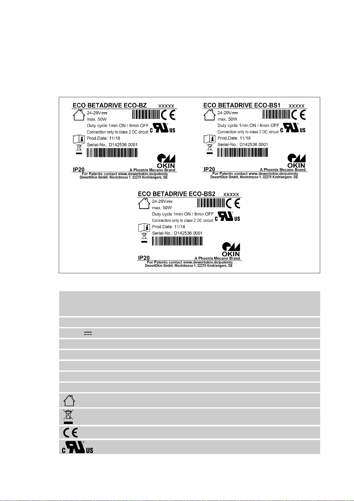
2.3 Ratings plate
The ratings plate shown is an example; the specifications for your drive may differ from this illus-
tration.
Figure 2 Ratings plate example
ECO BETADRIVE ECO-BZ
ECO BETADRIVE ECO-BS1
ECO BETADRIVE ECO-BS2
Model name
xxxxx
Article number
24-29V
Input voltage
max. 50W
Power consumption
Duty cycle: 1 min ON /8 min OFF
Mode of operation
Prod. Date
Calendar week / year
Serial-No.
Serial number for your drive
IP20
Protection degree
Use in dry rooms only!
Follow all special disposal instructions!
Mark of CE conformity
Mark of Underwriters Laboratories (UL)

ECO BETADRIVE ECO Description
81417 3.0 9
3. Description
The ECO BETADRIVE ECO is an electrically driven motor that is responsible for moving the end
product in a linear direction. This adjustment is created by the up and down movement of a actuat-
ing block. The ECO BETADRIVE ECO is controlled using an Okin handset.
The technical specifications for the variants are listed in Chapter 4Fehler! Verweisquelle konnte
nicht gefunden werden. "Technical Specifications".The variants differ according to their:
Working performance,
Speed,
Pushing and pulling forces,
Dimensions and stroke,
Connection variants (refer to section 3.2.3
3.1 Components
Figure 3 Main components of the ECO BETADRIVE ECO
AProfile cap
BGuidance profile
CGear clevis
EActuating block
DDrive housing
FOptional: Socket for handset
B
A
C
E
F
D

Description ECO BETADRIVE ECO
10 81417 2.0
3.2 Installation options for the end product
3.2.1 Installation for the guideance profile
Installation on the guidance profile For the ECO BETADRIVE ECO, there are two installation options for the guidance profile:
Profile cap
Profile cap and mounting bracket
Figure 4 Installation options on the guidance profile
A Profile cap with screwed mounting
bracket on the ECO BETADRIVE ECO
B Profile cap
A
B

ECO BETADRIVE ECO Description
81417 3.0 11
3.2.2 Installation at the motor housing
For the ECO BETADRIVE ECO, there are two installation options for the motor housing:
Clevis
Clevis and mounting bracket
Figure 5 Installation options at the motor housing
A Clevis with screwed mounting bracket on
the ECO BETADRIVE ECO
B Clevis
A
B

Description ECO BETADRIVE ECO
12 81417 2.0
3.2.3 Connection options
There are different power supply options for the ECO BETADRIVE ECO:
LSP plug,
5-pole plug,
Motor controller cable.
Figure 6 Connection options
A Connection at the side of the motor housing
B Connection at the side of the profile cap
C LSP plug
E Motor controller cable
E1 Handset connection
E2 Power supply connection
D 5-pole plug
B
A
E
C
D
E2
E1

ECO BETADRIVE ECO Technical Specifications
81417 3.0 13
4. Technical Specifications
Input voltage
24 V DC - 29 V DC
Current consumption at rated load
max. 4.0 A, depending on version (refer to the ratings
plate)
Permitted push force
max. 1500 N, depending on version (refer to the rat-
ings plate)
Permitted pull force
max. 1500 N depending on version
Mode of operation1) under max. rated
load
Intermittent duty 1 min ON / 8 min OFF
Protection class2)
III
Noise level
≤ 65 dB(A)
Drive type
Push / pull
Belastungsart
Druck; Zug
Adjustment speed3)
up to 44 mm/second, depending on the version
Protection degree
IP20
Stroke
< 500 mm
Colours
Black
Dimensions and weight
Length x width x height
max. 720 mm x 177 mm x 81 mm
Weight
approx. 2.0 kg, depending on version
Ambient conditions for operation, storage and transport
Transport / storage temperature
from -20 °C to +50 °C
from -4 °F to +122 °F
Operating temperature
from +10 °C to +40 °C
from +50 °F to +104 °F
Relative humidity
from 30% to 75%
Air pressure
from 800 hPa to 1060 hPa
Height
< 2000 m
1) Mode of operation: intermittent duty 1 min/ 8 min. This means that after the unit is operated with its rated
load for up to one minutes it must then be paused for 8 minutes. The system can malfunction if this pause
is not observed!
2) Safety extra low voltage
3) Adjustment speed: the speed at which the clevis can move under no load (the speed varies depending on
the load).

Technical Specifications ECO BETADRIVE ECO
14 81417 2.0
Figure 7 Dimensions of the ECO BETADRIVE ECO (in mm),
min. installation dimension: 157 mm
23
23
Ø5
M10
173
81
177
66
min. 157
14,5
97

ECO BETADRIVE ECO Installation
81417 3.0 15
5. Installation
5.1 Safety notices to observe during installation
Basic safety rules must be followed in order to ensure that the end product can be continually op-
erated in a safe manner. The following rules must be observed while using the end product and
while installing the drive
Avoiding fatigue fractures
Install the drive in the end product so that it is properly aligned. This will help prevent shear
stress.
Do not position the drive at a slanted angle when installing it in the end product. A slanted angle
between the intended direction of movement of the end product and the drive's direction will
create shear stress and could lead to a fatigue fracture.
Be sure to install the drive so that it can always move freely in all operative states.
Avoiding an overrun of the stop point with the end product
Your end product should contain mechanical end stops. These will limit the drive movement and
significantly increase operational safety. DewertOkin recommends that you build such mechani-
cal end stops into your end product.
Be sure that your operating instructions inform the user of these points.

Installation ECO BETADRIVE ECO
16 81417 2.0
5.2 Installation procedure
NOTICE
Carry out the assembly of the drive when the application is in no-load position.
In its final position, the drive must be either fully retracted or extended.
Damage to the drive is prevented only in in no-load position and a safe assembly is ensured.
An example installation
First example: Profile cap with mounting bracket / clevis with mounting bracket.
Figure 8 Installing the drive (example)
A End product
B Adaption mechanism of the end product
C Mounting bracker on the side of the profile
cap
D Mounting bracket on the side of the clevis
E Actuating block
F Self-tapping screw Ø6,3 x max.25mm
(DIN EN ISO 1478)
In the following example, installation of the ECO BETADRIVE ECO into the end product is shown.
Certain details may change as a result of technical changes.
1 Move your product into a position where it is supporting no load.
2 Put the drive onto the end product (A).
3 Screw the mounting bracket (C / D) onto the end product (A).
4 Screw the adaptive mechanism (B) to the actuating block (E).
Use self-tapping screws Ø6.3 x max.25 mm (DIN EN ISO 1478).
Recommended torque for the self-tapping screws: Max. 6 Nm
5 You may now connect the ECO BETADRIVE ECO electrical connection.
F
B
C
E
A
B
A
D

ECO BETADRIVE ECO Installation
81417 3.0 17
Second example: Clevis
Figure 9 Installing the drive (example)
A Clevis
B Adaption mechanism of the end product
C Mounting bolt
D Safety clip
E Actuating block
F Self-tapping screw Ø6,3 x max.25mm
(DIN EN ISO 1478)
G Bracket for securing the drive
In the following example, installation of the ECO BETADRIVE ECO into the end product is shown
using.
Certain details may change as a result of technical changes.
Figure 10 Steps for installing the clevis (example)
1 Move your product into a position where it is supporting no load.
2 Push the drive's clevis (A) onto the bracket (G).
3 Insert the mounting bolt (C) into the bracket (G).
4 Secure the mounting bolt (C) with the safety clip (D).
5 Screw the adaptive mechanism (B) to the actuating block (E).
Use self-tapping screws Ø6.3 x max.25 mm (DIN EN ISO 1478).
Recommended torque for the self-tapping screws: Max. 6 Nm
6 You may now connect the ECO BETADRIVE ECO electrical connection
1
2
3
C
A
G
D
E
F
B
B

Installation ECO BETADRIVE ECO
18 81417 2.0
5.2.1 Electrical connection
CAUTION
Danger of crushing injury!
The electrical components may be connected or disconnected only when the mains power and
the battery plug (when present) are disconnected. This ensures that no uncontrolled movement
can be triggered.
If the hand switch will be used to control two drives, you must first connect both drives electrical-
ly to each other (for example, over a control unit or double drive). Then you can connect the
handset.
Routing the electrical cables
When routing the cables, be sure that:
the cables cannot get jammed,
no mechanical load (such as pulling, pushing or bending) will be put on the cables,
or
the cables cannot be damaged in any way.
Fasten all cables (especially the mains cable) to the end product using sufficient strain relief and
kink prevention methods. Be sure that the design of the end product prevents the mains cable from
coming into contact with the floor during transport.
6.2.2. Dismantling
CAUTION
Danger of crushing injury
The electrical components may be connected or disconnected only when the mains power
and the battery plug (when present) are disconnected. This ensures that no uncontrolled
movement can be triggered.
Be sure to carry out work on the drive in a position so that no loads are bearing on it. Only in
this way can you be sure to avoid any risks of crushing or injury.
1 Move your product into a position where it is supporting no load.
2 If multiple drives are connected electrically they should be disconnected from each other.
3 Remove the srews of the adaption mechanism.
4 Remove the security clips and the mounting bolt,
or remove the srews of the mounting bracket from the end product.

ECO BETADRIVE ECO Note: Operating information
81417 3.0 19
6. Note: Operating information
The installation instructions do not contain all information required for the safe operation of the end
product. They only describe the installation and operation of the drive as components (as defined in
the Machinery Directive as a "partially assembled piece of machinery").
Power-on time / intermittent operations
NOTICE
The ECO BETADRIVE ECO has been designed for intermittent operations. Intermittent opera-
tion is an operational mode where the drive must pause after a specified maximum period of
operation (power-on time). The drive can overheat when these pauses are not maintained.
The ECO BETADRIVE ECO must operate with an intermittent duty of 1 min/ 8 min. This means
that after the unit is operated with its rated load for up to one minutes it must then be paused for
8 minutes.
Shutting off the drive
In order to shut off the drive, unplug the mains power plug and the battery plug (when present)! The
power plug must always be accessible during operations so that emergency shut-off is possible.
Avoiding cable damage
Be sure that your operating instructions inform the user about the possible cable risks.
NOTICE
The cables (in particular the electrical connection for the drive and the power supply cable for the
drive system) must not be squashed or crushed. In order to prevent damage to the drive, no
mechanical strain should be placed on the cables.

Maintenance and cleaning ECO BETADRIVE ECO
20 81417 2.0
7. Maintenance and cleaning
7.1 Maintenance
The ECO BETADRIVE ECO is maintenance free.
7.2 Cleaning
Clean the ECO BETADRIVE ECO as needed using a dry antistatic cloth.
NOTICE
Always disconnect the mains power plug from the drive system (and the battery plug if pre-
sent) before you start to clean the unit!
Never clean the drive in an automated washing system or with a high-pressure cleaner. Do
not allow fluids to penetrate the drive. Damage to the system could result.
Do not use a cleanser that contains benzene, alcohol or similar solvents.
Make sure that you do not damage the drive's connecting cable.
This manual suits for next models
3
Table of contents
Other dewert okin DC Drive manuals


