Dexion ME047-03-000V User manual

- 11 -
index
CHAPTER DESCRIPTION PAGE
general remarks ................................................................................................................................... 1 2
1 . T ec h nic al d ata ...................................................................................................................................... 1 3
1 .1 T ab le I glass-c eramic c o o kers and c o o kto p s ....................................................................................... 1 3
1 .2 T ec h nic al c h arac teristic s ..................................................................................................................... 1 3
1 .3 E lec tric al h eating ................................................................................................................................. 1 3
2 . Installatio n instru c tio ns ....................................................................................................................... 1 3
2 .1 Info rmatio n ab o u t glass-c eramic c o o kers and c o o kto p s ..................................................................... 1 4
2 .2 L aw s, regu latio ns and tec h nic al d irec tiv es .......................................................................................... 1 4
2 .3 Installatio n p lac e .................................................................................................................................. 1 4
2 .4 P o sitio ning ........................................................................................................................................... 1 4
2 .5 M o u nting th e to p u nits o n a b ase o r an ex tend ing su p p o rt ................................................................. 1 4
2 .6 E lec tric al c o nnec tio n ........................................................................................................................... 1 4
2 .6 .1 E arth ing ............................................................................................................................................... 1 5
2 .6 .2 E q u ip o tential ....................................................................................................................................... 1 5
2 .6 .3 P o w er su p p ly c ab le .............................................................................................................................. 1 5
2 .6 .4 A d v ic e to fitters ................................................................................................................................... 1 5
2 .6 .5 C o nnec tio ns to v ario u s main p o w er su p p lies ...................................................................................... 1 6
3 . R ep lac ing imp o rtant c o mp o nents ........................................................................................................ 1 7
4 . U ser’s instru c tio ns ............................................................................................................................... 1 7
4 .1 G lass-c eramic w o rk to p ....................................................................................................................... 1 7
4 .2 Installatio n o f th e elec tric ity -fed h eating elements ............................................................................. 1 7
4 .3 U so o f th e c o o king areas ..................................................................................................................... 1 7
4 .4 U sing th e static elec tric o v en ............................................................................................................... 1 8
4 .5 C o o king w ith th e o v en ........................................................................................................................ 1 9
5 . M aintenanc e and c leaning ................................................................................................................... 1 9
IN S T A L L A T IO N D IA G R A M S M E 0 4 7 -0 3 -0 0 0 V ............................................................................. 2 0
IN S T A L L A T IO N D IA G R A M S M E 0 7 7 -0 3 -0 0 0 V ............................................................................. 2 1
IN S T A L L A T IO N D IA G R A M S M E 0 7 7 -0 3 -0 1 4 V ............................................................................. 2 2
E L E C T R IC A L D IA G R A M S M E 0 4 7 -0 3 -0 0 0 V .................................................................................. 2 3
E L E C T R IC A L D IA G R A M S M E 0 7 7 -0 3 -0 0 0 V .................................................................................. 2 4
E L E C T R IC A L D IA G R A M S M E 0 7 7 -0 3 -0 1 4 V .................................................................................. 2 5

- 12 -
general remarks
- Carefullyreadtheinstructionscontainedinthepresentbookletastheysupplyimportantinformationrelatingto
safeinstallation,useandmaintenance.
- Keepthisbookletwithcare,foranyfurtherconsultationbythevariousoperators.
- Havingremovedthepacking,makesuretheunitisingoodorderandincaseofdoubt,donotusetheunit,butcall
onskilledpersonnel.
- Beforeconnectingtheunit,makesurethedataappearingontheserialplatecorrespondtothoseofthemain
electricsupply.
- Theunitmustbeusedonlybyapersontrainedforitsoperation.
- Beforeperformingcleaningorservicingoperations,disconnecttheunitfrom theelectricsupply.
- Shutofftheunitincaseoffaultorbadfunctioning.Foranyrepairs,pleasecallexclusivelyanauthorisedtechnical
servicecentre,andaskfororiginalsparepartsonly.Noncompliancewiththeabovemaycompromisetheunit’s
safety.
- Thisunitmustonlybeusedforthepurposeitwasexpresslybuiltfor.
- Donotwashtheunitwithdirectorhigh-pressurewaterjets.
- Donotobstructopeningsordraftgridsorheatvents.
- Electricalsafetyisguaranteedonlybyanefficientearthingsystem,asenvisagedbytheelectricalsafetyregulation
inforce:itisthereforenecessarytoverifythisessentialrequisiteand,incaseofdoubt,requestanaccurate
check-upbyprofessionallyqualifiedpersonnel.
- TheManufacturercannotbedeemedresponsibleforanydamagescausedbythelackofearthinginthesystem.
- Theunitmustbeincludedinanequipotentialsystem whoseefficiencyshouldbetestedincompliancewiththe
law inforce.
- Allunitsaresuppliedwitha200cm longcablehavingthecharacteristicsshowninTab.3.
- Thehook-upwireforthepowersupplyconnectionshouldnothavecharacteristicsbelow thetypewithrubber
insulationH07RN-F
- Incaseofnon-compliancewiththeindicationscontainedinthepresentmanual,bothontheuser’spartandon
theinstallingtechnician’spart,theManufacturerdeclinesanyresponsibility,andanypossibleaccidentorfault
causedbytheabovementionednon-complianceswillnotbeimputabletotheManufacturer.

- 13 -
1. TECHNICAL DATA
1.1 GLASS-CERAMIC COOKERS AND COOKTOPS
1.2 TECH NICAL CH ARACTERISTICS
STRU CTU RE Stainless steel frame AISI 304, stainless steel panels and base mounted on height-adjustable feet.
TOP in glass-ceramic.
ENERGY REGU LATORS that ensure the control of the cooking surfaces and the correct adjustment of their temperatures.
CONTROL KNOB S made of insulated material.
OV EN GN2 /1
COOKING CH AMB ER in high-temperature and acid resistant porcelained steel, with internal dimensions complying to
GASTRONORM 2/1. Thermal insulation with high-density glass wool. Grill’s lateral supports made of chromate steel bars,
easily extractable for cleaning. Grill made of chromate steel bar.
OV EN DOOR with double panelling and insulating glass wool interspace, door headers of enamel steel, handles mounted on
athermal supports, and door seal. B alanced spring hinges.
1.3 ELECTRICAL H EATING
- Electric heating elements in reinforced stainless steel are located in the cooking chamber.
- Selector switch with 50÷ 300° C thermostat and the following functions:
• F ull oven heating 4400W (upper and lower heating elements on)
• Lower heating element 3200W
• Upper heating element 1200W
• Grill heating element 2750W
- Indicator lights to signal the switching on and functioning of the thermostat.
*VOLTAGE SUPPLY: 3N AC 400V;3 AC 230V;1N AC 230V 50/60Hz
N.B.: power absorbed with 3N AC 380V ;3 AC 220V;1N AC 220V 50/60Hzis approx 9% less
power absorbed with 3N AC 415V;3 AC 240V;1N AC 240V 50/90Hzis approx 9% upper
2 . INS TALLATIO N INS TR U CTIO NS
In s ta lla tio n m u s t b e p e r fo r m e d b y q u a lifie d te c h n ic ia n s a c c o r d in g to th e la w in fo r c e .
W ARNINGS:
Should the unit be installed against a wall, the latter must be heat-resistant to temperatures of 100° C and must be fireproof.
B efore proceeding with the installation, remove the protective plastic film from the relevant parts, eliminating any adhesive
residues with an appropriate cleaning product suitable for stainless steel.
Install the unit in a horiz ontal position; its correct levelling will be achieved by rotating the adjustable feet.
If the unit is installed by itself, it is advisable to fasten it to make its stability safer.
MODEL DIMENSIONS in m m
external
ME047-03-000V
ME077-03-000V
ME077-03-014V
400x700x290/425
700x700x290/425
700x700x850/985
LxPxA/A max
oven
GN2/1
-
-
560x630x295
LxPxA
ABSORBED POW ER*
Ø 180
1800W
1
2
2
Ø 230
1800W
(1000+
14000)
forno
4400W
-
-
1
grill
2750W
-
-
1
totale
kW
4,2
8,4
12,8
NET
W EIGHT
20
35
90
kg
tab.1
1
2
2

- 14 -
2.1 INFORMATION ABOUT GLASS-CERAMIC COOKERS AND COOKTOPS
The serial plate is located as follows:
a) for units with oven, on the door and inside.
b) for units without oven, on the lower left side of cabinet and inside.
2.2 LAW S, REGULATIONS AND TECHNICAL DIRECTIVES
The following indications should be observed during installation:
- Accident and fire regulations in force
- The regulations of the electric power supply company.
- H ygienic regulations.
- The rules for electrical systems.
2.3 INSTALLATION PLACE
- The unit should be installed in adequately ventilated places.
- Install the unit in compliance with the safety regulations.
2.4 POSITIONING
- The various units may be installed individually or together with other units of our range
- This unit is not suitable for encasing.
- The distance between side walls must be a minimum of 10cm; should the distance be less or the wall or floor material be
flammable, it is essential to use a thermal insulator.
2.5 MOUNTING THE TOP UNITS ON A BASE OR AN EX TENDING SUPPORT
(Side illustration)
All Top units are supplied with height-adjustable feet (P):
- When the unit is to be placed free on a table or a surface,
tighten or loosen the feet (P) as shown in the illustration
till it is perfectly steady, then tighten the locknut (D) so
that the foot is blocked. To prevent slipping, insert the
rubber plugs (M) into the feet’s lower holes.
- When the unit is to be fixed to a base or an extending
support, adjust the feet (P) till it is perfectly steady, then
tighten the locknut (D) so that the foot is blocked.
Subsequently fasten from beneath by way of M5 screws
(T) and respective washers, screwing them into the feet as
shown in the illustration.
2.6 ELECTRICAL CONNECTION
Electrical connection should be performed in compliance with the IEC regulations, only by authorised and competent personnel.
In the first instance, examine the data shown on the technical data table of this manual, on the label and on the electrical
diagram. The envisaged connection is of the fixed type.

- 15 -
IMPORTANT: Ahead of each unit it is necessary to install an omnipolar main breaker, having a spacing among contacts of
at least 3mm; example:
- manual breaker of appropriate capacity, complete with fuse valves
- automatic breaker with respective magnetothermal relays.
2.6.1 EARTHING
It is essential to earth the unit.
To this purpose, it is necessary to connect to an efficient earthing system the terminals marked with the symbols ( ) placed
on the line-receiving terminal box. The earthing system should comply with the law in force.
SPECIFIC WARNINGS
The electrical safety of this unit is assured only when it is correctly connected to an efficient earthing system as stated
in the electrical safety regulations in force; the Manufacturer declines any responsibility for the non-compliance with
these safety regulations.
It is necessary to verify this fundamental safety requisite and, in case of doubt, ask for an accurate testing of the system by
professionally qualified personnel.
The Manufacturer cannot be deemed responsible for any damages caused by the lack of unit earthing.
ATTENTION: NEVER INTERRUPT THE EARTH WIRE (Yellow-Green)
2.6.2 EQ UIPOTENTIAL
The unit should be included within an equipotential system whose efficiency must be tested according to the law in force. The
screw marked with the label “ Equipotential” is located near the terminal box on the base for models with oven, and at the back
for the remaining models.
26.3 POWER SUPPLY CABLE
The unit is supplied fitted for the following voltages:
3N AC 380...415V; 3 AC 220...240V; 1N AC 220...240V 50/60 Hz.
The flexible cable for power supply connection should not have characteristics lower than the rubber insulation type
H07RN-F. The cable should be inserted through the cable clamp and firmly fastened. Furthermore, the supply voltage with
the unit functioning should not go outside the value of the nominal tension ± 10% .
To have access to the terminal box in order to connect the unit to a supply network having different characteristics from those
provided for, or to replace the supply cable, you need to:
- remove the front panel (top or top + cabinet)
or
- remove the appropriate panel on the left side (cooker with electric oven)
- connect the cable to the terminal box according to need, and following the instructions shown on the provided sticker near
the terminal bord and on the present booklet.
2.6.4 ADVICE TO FITTERS
Activate the unit according to the use instructions, and explain its operation to the user by consulting the instruction booklet,
illustrating also any manufacturing and/or functional modifications.
Leave the instruction booklet with the user, advising that he/she should refer to it for any future consultation.

- 16 -
2.6.5 CONNECTIONS TO VARIOUS MAIN POWER SUPPLIES
3N AC 380...415 V 50/60 Hz
PE (earth) yellow-green
N (NP) blue
L3 (T) black
L2 (S) black
L1 (R) brown
2N AC 380...415 V 50/60 Hz
PE (earth) yellow-green
N (NP) blue
L2 (S) black
L1 (R) brown
3 AC 220...240 V 50/60 Hz
PE (earth) yellow-green
N (NP) blue
L3 (T) black
L1 (R) brown
1 AC 220...240 V 50/60 Hz
PE (earth) yellow-green
N (NP) blue
L1 (R) brown
Tab.2
Tab.3
MODEL
SUPPLY VOLTAGE TYPE
ME047-03-000V ME077-03-014VME077-03-000V
Max.
A/f
n°cables
mm2
3 N AC 380...415 V 50/60 Hz
2 N AC 380...415 V 50/60 Hz
3 AC 220...240 V 50/60 Hz
1N AC 220...240 V 50/60 Hz
10,4
10,4
15,9
18,3
5 x 1,5
4 x 1,5
4 x 1,5
3 x 2,5
Max.
A/f
n°cables
mm2
15,7
20,9
22,7
36,5
5 x 1,5
4 x 2,5
4 x 2,5
3 x 6
Max.
A/f
n°cables
mm2
19,1
36,5
32,4
55,7
5 x 2,5
4 x 6
4 x 6
3 x 10
ELECTRICAL DIAGRAM
DRAWING N° 1372 1371 1370

- 17 -
The replacements described below should only be performed by an “Authorised Service Centre”.
Before replacing any component, you should shut off power supply from the unit by using the omnipolar switch.
A) Switch, thermostat and energy regulators
- remove the dashguard
- undo the screws fastening the component
- remove the thermostat from the switch by carefully bending the two clips of the fastening bracket (for oven controls only)
- remove the protection of the thermostat bulb and pull it off the fastening clips (oven chamber thermostat only)
- disconnect the wires following the electrical diagram
- replace the component and re-assemble everything back, using the electrical diagram
- mount back each part following the reverse sequence.
B) Ov en heating elements
- unscrew the plate for the oven chamber heating element from the inside
- take out the heating element from the suitable opening, and detach the all wires and at last the protection one
- install the new element referring to the electrical diagram
- mount back each part following the reverse sequence.
3. REPLACING IMPORTANT COMPONENTS
4 . USER’S INSTRUCTIONS
4.1 GLASS-CERAMIC WORK TOP
The work tops are equipped with two or four irradiation electricity-fed heating elements, with a two-level power and various
diameters, as shown in point N. 3.
The cooking areas are clearly indicated onto the work tops thanks to circles that represent the limits of the heating area ; each
area is controlled by a handle that activates an energy regulator (please see installation diagrams).
The residual heat warning lights are easily visible onto the work top ; they switch on when the relevant area reaches 60°C and
stay lit until the temperature has not reached below that value.
4.2 INSTALLATION OF THE ELECTRICITY-FED HEATING ELEMENTS
The weaker electric element (1.8 kW) is composed of one heater only and is activated by the relevant handle (see figure 1) ;
by turning it clockwise, it switches on until it reaches the maximum temperature in correspondence with point 3 ; set the
handle on 0 to switch the equipment off.
The stronger electric element (2.4 kW) is composed of two heaters that are also activated by the relevant handle ; by turning
it clockwise the inner heater turns on (1.0 kW) ; it reaches the highest temperature when it is set onto point N. 3 ; if you are
using a large-sized pan, you also have to install the external heater (1.4 kW) ; by turning the handle over point N. 3 you will
hear a click that guarantees the activation of the second heater.
If you move the handle and if you set it into all positions from 1 to 3, you will obtain the desired temperature in the cooking
area. By setting the handle to “0”, both heaters will be switched off.
WARNING ! ! The more powerful cooking area is heated by two independent heaters and has been specially conceived in
order to be used for the small-sized pans and the frying pans by simply using the internal electricity-fed heater as explained
earlier. .
4.3 USE OF THE COOKING AREAS
- 18 -
- Before switching on the heater that corresponds to the desired cooking area, please make sure that the diameter of the pan
that you are using is correct ; also make sure that the bottom is perfectly flat and is quite thick (please use pans and frying
pans with multi-layer bottom) ; the most important thing is that the pan has to be perfectly dry ; now lay the pan onto the unit
and make sure you put it onto the centre of the cooking area.
- Do not drag the pans onto the glass-made work top in order to avoid any scratch.
- Even after use, the cooking areas keep the heat for a long time ; never lay your hands or any other object onto this area until
the residual heat warning light has not turned off.
- If you see a crack onto the glass surface, switch off and immediately disconnect the unit.
- Please keep all materials or substances that may melt down (such as plastics or aluminium foils) away from the cooking
surface. If, inadvertently, something has melt onto the work top, immediately hot-clean with a scraper.
- Never use the cooking surface as a support or as a work top.
4.4 USING THE STATIC ELECTRIC OVEN
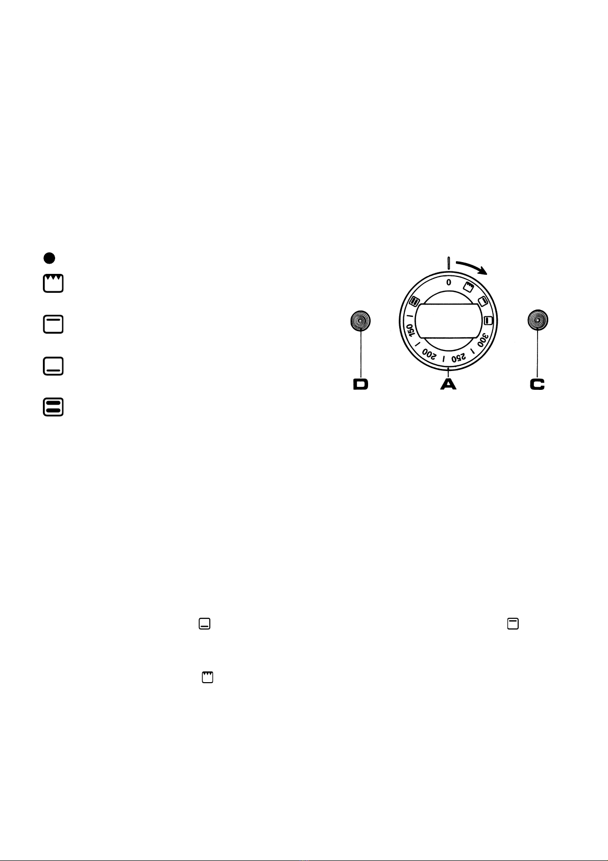
OVEN KNOB SYMBOLS
Oven off
The grill is switched on 2750 W
with thermostat control
The upper part is switched on 1200 W
with thermostat control max 300°C
The lower part is switched on 3200 W
with thermostat control max 300°C
The lower and the upper part are switched
on 4400 W with thermostat control max 50+300°C
fig. 6
WARNING: Before turning on the oven, make sure that no plastic bags and no paper of cardboard are inside the oven.
USING THE OVEN
- Turn the knob clockwise onto the desired position (Pos. A - Fig. 2).
- The green flash light will light up to show that the oven is on.
- If the orange flash light lights up (Pos. C - Fig. 2), this means that the thermostat is working and that the oven is heating up.
When the desired temperature has been reached (Pos. A - Fig. 2) the orange flash light goes off and food may be put into the
oven.
- The door must be thoroughly shut while cooking.
- When the food is cooked, turn off the oven by turning the knob back onto ‘O’ position.
N.B.: Differentiated temperatures for different types of food may be obtained by concentrating the heat either in the
lower or in the upper part of the oven.
By turning the knob to the right onto the 3200 W power resistor is switched on; By turning the knob onto only
the upper 1200 W power resistor is switched on.
USE OF THE GRILL
- Turn the knob clockwise onto the position.
- The grill resistor with a power of 2750 W becomes white-hot, and the yellow and green flash-lights light up.
- While the grill is on, the door of the oven may be partially open.
- The grill is useful to cook au gratin.
- To switch of the grill, turn the knob to the left onto the “0” position.
IMPORTANT: before using the oven for the first time heat it up to its maximum temperature for 30 - 40 minutes keeping the
oven door closed to burn possible oil residues which could lead to unpleasant smells.

- 19 -
4.5 COOKING WITH THE OVEN
Select the temperature between 150 and 300 °C. To reach optimum results it is advisable to preheat the oven. Therefore only
put the food into the oven once the orange light has turned off, that is when the oven has reached the desired temperature.
Only fat meat may be put into the oven when it is still cold.
It is advisable to cook frozen meet without previously unfreezing it. In this case, select a temperature 20°C lower than normal
and add to the average cooking time for fresh meat.
Higher tins are more suitable in that they enable to avoid soiling the oven surface.
GLASS-CERAMIC COOKING SURFACE
Before performing any cleaning operation, disconnect the unit from the electricity network and abide by the following
instructions.
We recommend you to clean the work top before it completely cools down ; first remove all residues fell during cooking with
the help of a scraper (figure 5) ; then use some drops of a specific detergent and clean the top with a cloth or with some kitchen
paper (figure 4).
Never use abrasive or corrosive detergents such as oven sprays, powders, stain removers or metal sponges.
Rinse the work top with water and dry it with a clean cloth or with some kitchen paper.
Warning!!! If, inadvertently, some sugar falls onto the work top during cooking, immediately switch off the top and remove
the stains with warm water and a scraper.
Before cooking foods that contain much sugar (such as jams), we recommend to cover the cooking top with a protective
substance, in order to avoid all possible damages caused by the product that flows over the cooking tank.
END OF COOKING AND END OF DAY CLEANING
To clean the oven make use of a specific fat removing product. All oven detergents contain high amounts of caustic soda.
Alkaline products are necessary to remove more resistant stains.
Caustic soda damages the skin, the eyes and the lungs. Therefore it is advisable to protect the skin, but in particular eyes and
hands, while cleaning the oven by using rubber gloves and special glasses.
Warnings:
Follow these steps:
1) Let the oven cool down to a temperature of 60°C, remove the fat stains.
2) Clean the oven starting from the lower part with the alkaline oven detergent, which has to be diluted carefully following
the instructions on the bottle. Use the non diluted product only on extremely resistant stains. Careful: Do not use
corrosive detergents.
3) Rinse the oven and the equipment with water.
4) Strew the door gasket regularly with talcum powder, at least every 15 days.
- Clean the stainless steel parts daily with soapy lukewarm water, then rinse well and dry throughly.
- Absolutely avoid to clean the stainless steel with common steel-wool, or common steel brushes and scrapers, as they may
discard ferrous particles which, on depositing, cause rust spots. Y ou may, if you like, use stainless steel-wool passed on
following the butter-finish direction.
- Should the unit remain unused for long periods, heavily rub all the steel surfaces with a cloth slightly wetted with vaseline
oil, in order to cover them with a protective film. Periodically ventilate the premises.
5. MAINTENANCE AND CLEANING
- 20 -
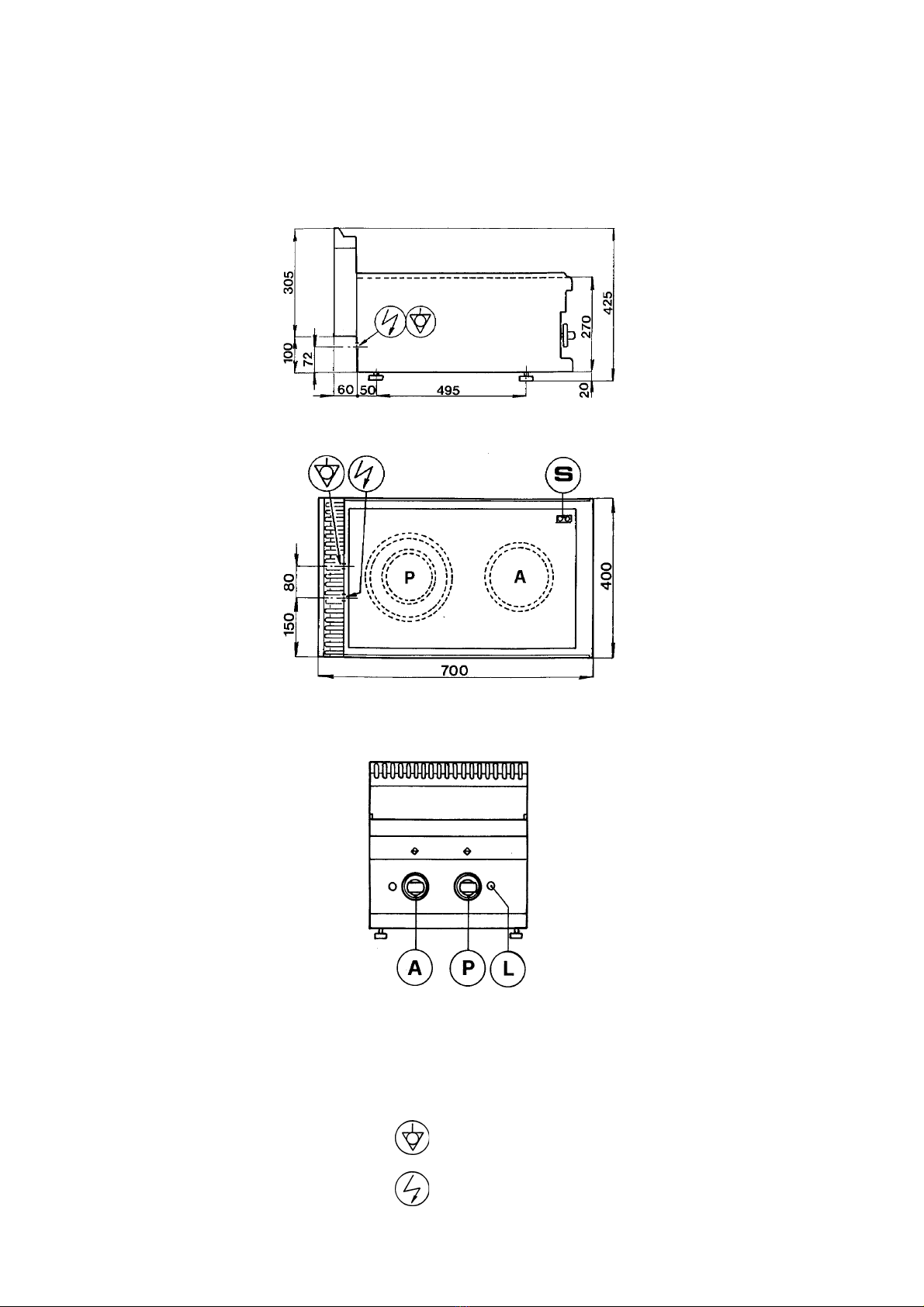
SCHEMI DI INSTALLAZIONE
INSTALLATION DIAGRAMS
ME047-03-000V
equipotenziale - equipotential
ingresso cavo d’alimentazione - supply cable entry
AD = piastra anteriore destra
right-hand side front plate
AS = piastra anteriore sinistra
left-hand side front plate
PD = piastra posteriore destra
right-hand side rear plate
PS = piastra posteriore sinistra
left-hand side rear plate
L = lampada spia in linea
line warning light
S = lampada spia di calore residuo
residual heat warningn light
F = manopola comando forno
oven operation handle

- 21 -
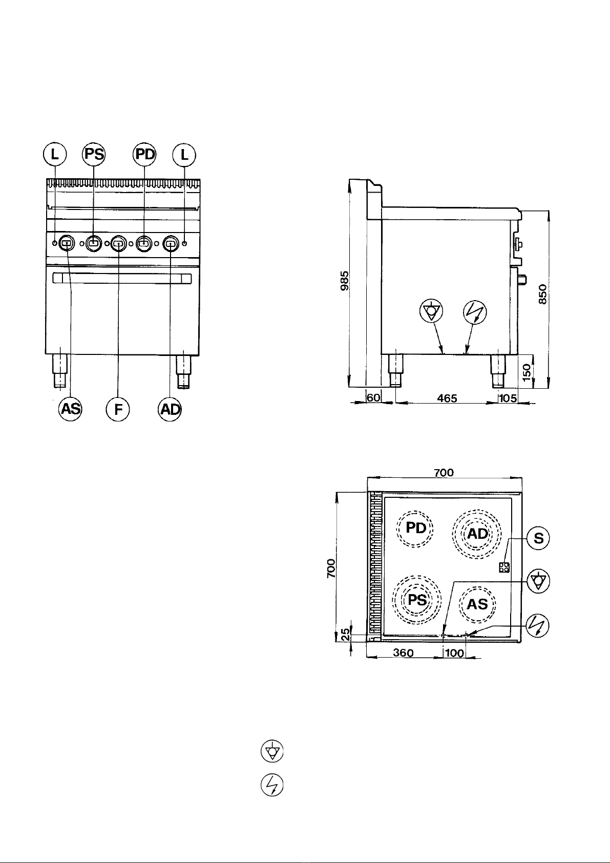
SCHEMI DI INSTALLAZIONE
INSTALLATION DIAGRAMS
ME077-03-000V
equipotenziale - equipotential
ingresso cavo d’alimentazione - supply cable entry
AD = piastra anteriore destra
right-hand side front plate
AS = piastra anteriore sinistra
left-hand side front plate
PD = piastra posteriore destra
right-hand side rear plate
PS = piastra posteriore sinistra
left-hand side rear plate
L = lampada spia in linea
line warning light
S = lampada spia di calore residuo
residual heat warningn light
- 22 -
SCHEMI DI INSTALLAZIONE
INSTALLATION DIAGRAMS
ME077-03-014V
equipotenziale - equipotential
ingresso cavo d’alimentazione - supply cable entry
AD = piastra anteriore destra
right-hand side front plate
AS = piastra anteriore sinistra
left-hand side front plate
PD = piastra posteriore destra
right-hand side rear plate
PS = piastra posteriore sinistra
left-hand side rear plate
L = lampada spia in linea
line warning light
S = lampada spia di calore residuo
residual heat warningn light

- 23 -
SCHEMA ELETTRICO - ELECTRICAL DIAGRAMS ME047-03-000V
ABBREVIAZIONE
ABREVIATION
SHORTNAME
KURZZEICHEN
n° codice
n° code
code n°
nr. codex
CA
M
RE1
RE2
L1 - L2
P1
P2
LS
-
RTBF900045
RIC0001010
RIC0001289
RTCU900290
RIC0001295
RIC001294
-
ITALIANO
CAVO D’ALIMENTAZIONE
MORSETTIERA
REGOLATORE D’ENERGIA
REGOLATORE D’ENERGIA
LAMPADA VERDE
PIASTRA ELETTRICA
PIASTRA ELETTRICA
LAMPADA SPIA
ENGLISH FRANCAIS DEUTSCH
POWER SUPPLY CABLE
TERMINAL BLOCK
POWER REGULATOR
POWER REGULATOR
GREEN LAMP
ELECTRIC HOB
ELECTRIC HOB
SIGNAL LAMPS
CABLE D’ALIMENTATION
PENNAU DE CONTROLE
REGULATEUR D’ENERGIE
REGULATEUR D’ENERGIE
LAMPE VERTE
PLAQUE ELECTRIQUE
PLAQUE ELECTRIQUE
LAMPES
ANSCHLUSSKABEL
KLEMMENLEISTE
ENRGIEREGLER
ENRGIEREGLER
GRUENE LAMPE
KOCHPLATTE
KOCHPLATTE
KONTRIKLAMPE

- 24 -
SCHEMA ELETTRICO - ELECTRICAL DIAGRAMS ME077-03-000V
ABBREVIAZIONE
ABREVIATION
SHORTNAME
KURZZEICHEN
n° codice
n° code
code n°
nr. codex
CA
M
RE2 - RE4
RE1 - RE3
L1 - L2
P2 - P4
P1 - P3
LS
-
RTBF900045
RIC0001010
RIC0001289
RTCU900290
RIC0001295
RIC001294
-
ITALIANO
CAVO D’ALIMENTAZIONE
MORSETTIERA
REGOLATORE D’ENERGIA
REGOLATORE D’ENERGIA
LAMPADA VERDE
PIASTRA ELETTRICA
PIASTRA ELETTRICA
LAMPADA SPIA
ENGLISH FRANCAIS DEUTSCH
POWER SUPPLY CABLE
TERMINAL BLOCK
POWER REGULATOR
POWER REGULATOR
GREEN LAMP
ELECTRIC HOB
ELECTRIC HOB
SIGNAL LAMPS
CABLE D’ALIMENTATION
PENNAU DE CONTROLE
REGULATEUR D’ENERGIE
REGULATEUR D’ENERGIE
LAMPE VERTE
PLAQUE ELECTRIQUE
PLAQUE ELECTRIQUE
LAMPES
ANSCHLUSSKABEL
KLEMMENLEISTE
ENRGIEREGLER
ENRGIEREGLER
GRUENE LAMPE
KOCHPLATTE
KOCHPLATTE
KONTRIKLAMPE

- 25 -
SCHEMA ELETTRICO - ELECTRICAL DIAGRAMS ME077-03-014V
ABBREVIAZIONE
ABREVIATION
SHORTNAME
KURZZEICHEN
n° codice
n° code
code n°
nr. codex
CA
M
RE2 - RE4
L1 - L5
P1 - P4
LS
CO1
T1
R1
R2
L6
-
RTBF900045
RIC0001010
RTCU900290
RIC0001295
-
RTCU700212
RTCU600067
RTCU700281
RTCU700282
RTCU900072
ITALIANO
CAVO D’ALIMENTAZIONE
MORSETTIERA
REGOLATORE D’ENERGIA
LAMPADA VERDE
PIASTRA ELETTRICA
LAMPADA SPIA
COMMUTATORE
TERMOSTATO
RESISTENZA INFERIORE
RESISTENZA SUPERIORE
LAMPADA ARANCIONE
ENGLISH FRANCAIS DEUTSCH
POWER SUPPLY CABLE
TERMINAL BLOCK
POWER REGULATOR
GREEN LAMP
ELECTRIC HOB
SIGNAL LAMPS
SWITCH
THERMOSTAT
LOWER HEATING ELEMENT
UPPER HEATING ELEMENT
ORANGE LAMP
CABLE D’ALIMENTATION
PENNAU DE CONTROLE
REGULATEUR D’ENERGIE
LAMPE VERTE
PLAQUE ELECTRIQUE
LAMPES
COMMUTATEUR
THERMOSTAT
RESISTANCE INFERIEUR
RESISTANCE SUPERIEUR
LAMPE ORANGE
ANSCHLUSSKABEL
KLEMMENLEISTE
ENERGIEREGLER
GRUENE LAMPE
KOCHPLATTE
KONTRIKLAMPE
HAUPTSCHALTER
THEMROSTAT
UTERER ROHREHIZDOERPER
OBERER ROHREHIZDOERPER
ORANGE LAMPE

- 26 -
fig. 2
fig. 4
fig. 5
This manual suits for next models
2
Table of contents
Popular Cooker manuals by other brands


Orbegozo
Orbegozo FO 6000 instruction manual

Smeg
Smeg C9IMXA manual

Currys Essentials
Currys Essentials CFSG10WH Instruction & installation manual

Bosch
Bosch HXA060B2 Q Series instruction manual

iLive
iLive Majestic UM30 User instructions, installation, maintenance

Mercury
Mercury 1000 Dual Fuel User's guide & installation instructions


