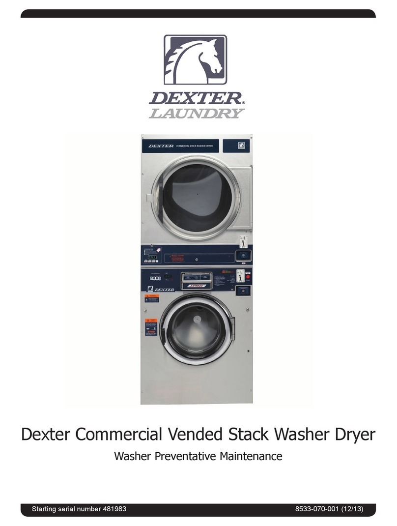
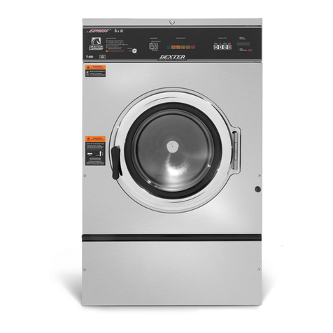
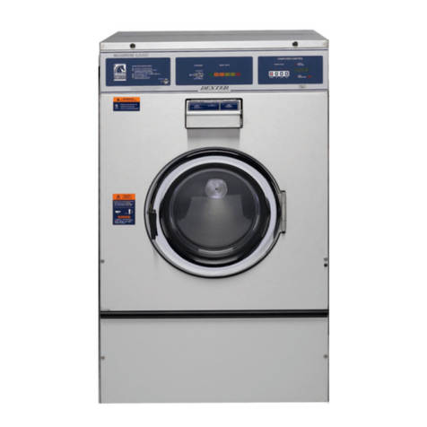
Dexter Laundry T350 Quick start guide

8533-104-001(1/18)
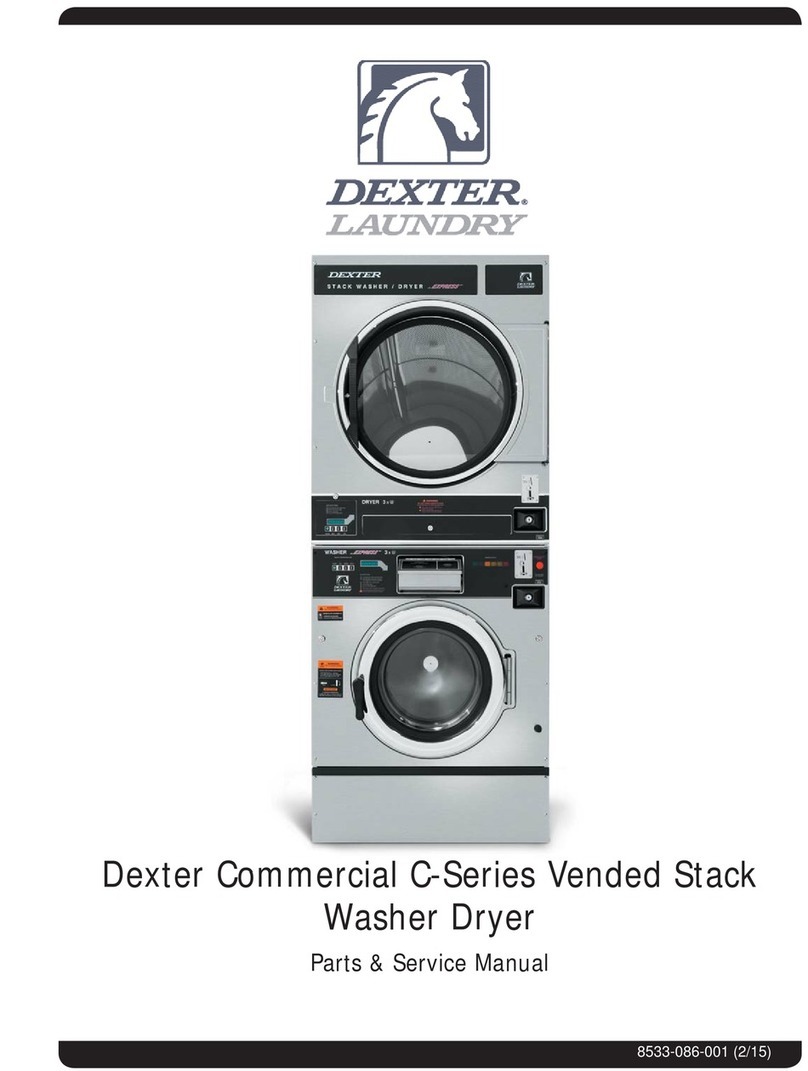
Dexter Commercial OPL Stack Washer Dryer
T-350
Parts & Service Manual
Starting serial number

2
Indicates an imminently hazardous situation, which if
not avoided, will result in death or serious injury.
Indicates a potentially hazardous situation, which if not
avoided could result in death or serious injury.
Indicates a potentially hazardous situation which, if not
avoided, may result in minor or moderate injury. It may
also be used to alert against unsafe practices. Minor
burns, pinch points that result in bruises and minor
chemical irritation.
Indicates information or a company policy that relates
directly or indirectly to the safety of personnel or protec-
tion of property.
This is the user caution symbol. It indicates a condition
where damage to the equipment resulting in injury to
the operator could occur if operational procedures are
not followed. TO REDUCE THE RISK OF DAMAGE OR
INJURY, refer to accompanying documents; follow all
steps or procedures as instructed.
This is the electrical hazard symbol. It indicates that
there are DANGEROUS HIGH VOLTAGES PRESENT inside
the enclosure of this product. TO REDUCE THE RISK OF
FIRE OR ELECTRIC SHOCK, do not attempt to open the
enclosure or gain access to areas where you are not
instructed to do so. REFER SERVICING TO QUALIFIED
SERVICE PERSONEL ONLY
Caution! There are sharp edges on various sheet metal
parts internal to the enclosure. Use safety consciousness
when placing or moving your hands while working in the
interior of this equipment.
Caution! To reduce the risk of damage to the Water Inlet
Valve, do not supply inlet water with a temperature that
exceeds 70˚ C.
Caution! To reduce the risk of re or explosion, do not
operate this equipment in any hazardous classied
(ATEX) environment.
Equipment Safety Warnings
Symbols and Terminology Used in this Equipment
Equipment Safety Warnings
Symbols and Terminology Used in this Equipment
Part # 8533-104-001 1/18

3
Equipment Safety Warnings
Symbols and Terminology Used in this Equipment
Warning! Do not operate equipment if door glass is
damaged in any way.
Warning! Keep clear of rotating parts.
Prohibited! Do not enter this equipment or space.
Prohibited! Do not step or stand on this equipment.
Prohibited! Do not operate without all guards and covers in
place.
Prohibited! Do not operate without all guards and covers in
place.
Prohibited! Do not wash clothing impregnated with
ammable liquids (petrochemical).
Prohibited! Do not allow children to play in or around
equipment.
Equipment Safety Warnings
Symbols and Terminology Used in this Equipment
Part # 8533-104-001 1/18

4
Indicates an imminently hazardous situation,
which if not avoided, will result in death or seri-
ous injury.
Indicates a potentially hazardous situation,
which if not avoided could result in death or
serious injury.
Indicates a potentially hazardous situation
which, if not avoided, may result in minor or
moderate injury. It may also be used to alert
against unsafe practices. Minor burns, pinch
points that result in bruises and minor chemical
irritation.
Indicates information or a company policy that
relates directly or indirectly to the safety of per-
sonnel or protection of property.
This is the user caution symbol. It indicates a
condition where damage to the equipment re-
sulting in injury to the operator could occur if
operational procedures are not followed.
TO REDUCE THE RISK OF DAMAGE OR INJURY,
refer to accompanying documents; follow all
steps or procedures as instructed.
This is the electrical hazard symbol. It indicates
that there are DANGEROUS HIGH VOLTAGES
PRESENT inside the enclosure of this product.
TO REDUCE THE RISK OF FIRE OR ELECTRIC
SHOCK, do not attempt to open the enclosure or
gain access to areas where you are not instruct-
ed to do so. REFER SERVICING TO QUALIFIED
SERVICE PERSONEL ONLY
Caution! To reduce the risk of re or explosion,
do not operate this equipment in any hazardous
classied (ATEX) environment.
Part # 8533-104-001 1/18

5
• All washers must be installed in accordance to
all applicable electrical, plumbing and all other local
codes.
• These installation and operation instructions are
for use by qualied personnel only. To avoid injury
and electrical shock, do not perform any servicing
other than that contained in the installation and op-
eration instructions, unless qualied.
Do not install washers in an explosive atmosphere.
•Care must be stressed with all foundation work to
ensure a stable unit installation, eliminating pos-
sibilities of excessive vibration.
•Foundation must be level within 13 mm to ensure
proper washer operation.
Do not operate washer if door glass is damaged in
any way.
Do not wash clothing impregnated with ammable
liquids (petrochemical).
WARNING
Part # 8533-104-001 1/18

6
Children should be supervised to
ensure they do not operate or play
in or around equipment.
Keep all panels in place to protect against electrical
shock and injury and add rigidity to washer.
WARNING
This appliance is not intended for use by persons (including
children) with reduced physical, sensory or mental capabilities, or
lack of experience and knowledge, unless they have been given
supervision or instruction concerning use of the appliance by a
person responsible for their safety.
A washer should not be allowed to operate if any of the following occur:
• Excessive high water level.
• Machine is not connected to a properly earthed circuit.
• Door does not remain securely locked during the entire cycle.
• Vibration or shaking from an inadequate mounting or foundation
Part # 8533-104-001 1/18

7
Warning! Do not operate equipment if door glass is
damaged in any way.
Warning! Keep clear of rotating parts.
Prohibited! Do not enter this equipment or space.
Prohibited! Do not step or stand on this equip-
ment.
Prohibited! Do not operate without all guards and
covers in place.
Prohibited! Do not operate without all guards and
covers in place.
Prohibited! Do not wash clothing impregnated
with ammable liquids (petrochemical).
Prohibited! Do not allow children to play in or
around equipment.
Part # 8533-104-001 1/18

8
Prohibited! Do not attempt to open, touch, or pro-
ceed before referring to the manual or unless quali-
ed.
Mandatory! Read all supporting documentation be-
fore operating or maintaining equipment.
Mandatory! Disconnect power before servicing
equipment.
Mandatory! Lock out and tag out before servicing
this equipment.
Mandatory! Disconnect water supply before servic-
ing equipment.
Mandatory! Children should be supervised to ensure
they do not operate equipment.
Part # 8533-104-001 1/18

9
Prohibited! Do not attempt to open, touch, or pro-
ceed before referring to the manual or unless quali-
ed.
Mandatory! Read all supporting documentation be-
fore operating or maintaining equipment.
Mandatory! Disconnect power before servicing
equipment.
Mandatory! Lock out and tag out before servicing
this equipment.
Mandatory! Disconnect water supply before servic-
ing equipment.
Mandatory! Children should be supervised to ensure
they do not operate equipment.
A machine should not be allowed to
operated if any of the following occur:
• Excessively high water level.
• Machine is not connected to a properly grounded
circuit.
• Loading door does not remain securely locked
during the entire cycle.
• Vibration or shaking from an inadequate mounting
or foundation.
Table of Contents
Section 1:
Specications, Mounting Dimensions
Specications..............................................14 - 15
Dimensions.................................................16 - 17
Section 2:
Installation & Operating Instructions
Washer Installation ........................................20
Electrical Connections & Fusing Requirements .21
Dryer Installation.................................................22
Dryer Electric, Gas and Venting.................23 - 24
Washer Operating Instructions..................25 - 26
Dryer Operating Instructions.................... 26 - 27
Section 3:
Washer and Dryer Programming Instructions
Wash Cycle Programming.......................30 - 33
Rapid Advance Mode......................................34
Dryer Programming...................................36 - 46
Section 4:
Dryer Service,Toubleshooting and Schematics
Dryer Service Procedures...........................48 - 54
Section 5:
Dryer Control Fault Codes..................................56
Dryer Troubleshooting Tips......................57 - 60
Dryer Schematics 60hz...........................62 - 63
Section 6:
Dryer Parts Data......................................66 - 85
Section 7:
50hz Gas Dryers
50hz Dryer Parts.....................................88 - 91
50hz Dryer Schematics............................92 - 93
Section 8:
Electric Dryer Parts
208 vac 3ph parts ................................96 - 97
240 vac 3ph parts .......................................97
400 vac 3ph 50hz parts................................98
Dexter Safety
Guidelines
FOR SAFETY
1. Always shut o power and water
supply and also discharge capacitors
before servicing.
2. Do not overload the washer.
3. Do not attempt to open door if cylinder
is in motion or contains water.
4. Do not mechanically force or override
door lock in any way.
5. Do not bypass any safety devices of
this washer.
6. Do not use volatile or ammable
substances in or near this washer.
7. Keep all panels in place. They protect
against shock and injury and add
rigidity to the washer.
To activate your warranty, be sure to return
your red warranty form to the factory. Please
have serial number and model ready when
calling for assistance.
WARNING
These washers are equipped with devices and
features relating to their safe operation. To
avoid injury or electrical shock, do not perform
and service, unless qualied to do so.
Part # 8533-104-001 1/18

10
Section 9:
Washer Service and Troubleshooting
Front Panel Removal .................................... 103
Back Panel Removal..................................... 103
Drain Valve Access .......................................103
Drain Valve Cleaning ....................................103
Detergent Dispenser ....................................103
Vaccuum Breaker/Air Gap ............................. 103
Water Valves ............................................... 103
Door Lock Assembly Operation .....................104
Adjustment for Door Lock Assembly........104-105
Adjusting the Loading Door .......................... 107
Loading Door Removal ................................. 107
Loading Door Hinge Removal........................ 107
Loading Door Disassembly ...........................108
Loading Door Reassembly ............................108
Control Panel Name Plate Decal....................108
Name Plate Removal ....................................108
Re-Installation of Name Plate........................108
Bolt Torque Chart.........................................108
Tub Back, Bearing and Cylinder Assembly .....109
Basket Pulley, Bearing Housing,
Water Seals & Tub Back .............................. 111
Control Mounting Trough.............................. 112
Main Data Communication Cable................... 112
Circuit Breaker/Fuse ..................................... 112
Main Control Printed Circuit Board................. 112
PCB Transformer Step Down......................... 112
Controls Transformer.................................... 112
Main Relay Printed Circuit Board ................... 112
LED Printed Circuit Board Temperature & Start
Display Push Button............................... 112
Add Bleach LED ........................................... 113
Power Connection Terminal Block ................. 113
Pressure Switch ...................................114 - 115
Delta Variable Frequency Drive ..................... 116
Delta VFD Motor Leads................................. 116
Delta VFD Dynamic Braking
Resistors ..................................................... 116
Delta VFD Cooling Fan ................................. 116
Washer Trouble Shooting and F - Codes...117-126
Section 9:
Washer Electrical & Wiring Schematics
Start Circuit .................................................128
Fill Circuit .......................................... 128 & 129
Wash Circuit ................................................129
Drain, Rinse 1 & 2 & Final Rinse Circuit .........129
Extract Circuit..............................................129
Thermoactuator and Shake Out Circuit..........130
End of Cycle Circuit ......................................130
Motor Winding Resistances...............................130
Washer Electrical & Wiring Schematics 60hz
................................................... 132 - 133
Section 10:
Washer Parts Data
SWD Accessories........................................136
Rear View Access Parts ..............................138
Cabinet and Front Panel Group .....................140
Cylinder, Seals & Bearings Parts .................142
Door Lock Parts ............................... 144 - 145
Loading Door Parts ........................... 146 - 147
Drain Valve Group Parts .............................148
Water Inlet Parts .......................................149
Chasis and Drain Parts....................................150
Electrical Components ....................... 152 - 153
Front Panel Control Group..............................154
Labels..............................................................155
Washer Electrical & Wiring Schematics 60hz
................................................... 156 - 157
Section 11:
50hz parts........................................................160
50hz Washer Schematics ......................162 - 163
Section 12:
Maintenance Dryer...........................................165
Maintenance Washer....................................166
Part # 8533-104-001 1/18
11
Part # 8533-104-001 1/18
Section: 1
Washer and Dryer
Specications and
Mounting

12
Stacked Washer Dryer Models
Stacked Model
Designation
Washer \ Dryer
Model #
Electrical Spec: Circuit Breaker
/ Running Amps / Wire Size/
Option
SN0350ND-17EP3X-
SWKCG-USX
9999-711-001
DNS020ND-15EB2X-
SWKCG-USX
9999-709-001
115-120 ,208-240/60/1, Single 2 Wire +
Ground,
WNS350XB-12EV3X-
SWKCS-USX
9999-707-001
208-240/60/1or3, Single 2 Wire + Ground, 3
Phase 3 Wire + Ground
SN0350ND-39AP3X-
SWKCG-VRX
9999-711-002
DNS020ND-39AB2X-
SWKCG-VRX
9999-709-003
230/50/1, Single 2 Wire + Ground
WNS350XB-39XV3X-
SWKCS-VRX
9999-707-002
230/50/1, Single 2 Wire + Ground
SN0350ED-84EP3X-
SWKCG-USX
9999-711-003
DNS020ED-84EB2X-
SWKCG-USX
9999-709-007
208/60/3 3 wires plus neutral and ground-
15kW Heating Elements
WNS350XB-12EV3X-
SWKCS-USX
9999-707-001
208-240/60/1or3, Single 2 Wire + Ground, 3
Phase 3 Wire + Ground
SN0350ED-85EP3X-
SWKCG-USX
9999-711-004
DNS020ED-85EB2X-
SWKCG-USX
9999-709-009
240/60/3 3 wires plus neutral and ground-
15kW Heating Elements N is earthed midpoint
of phase
WNS350XB-12EV3X-
SWKCS-USX
9999-707-001
208-240/60/1or3, Single 2 Wire + Ground, 3
Phase 3 Wire + Ground
SN0350ED-82XP3X-
SWKCG-VRX
9999-711-005
DNS020ED-82XB2X-
SWKCG-VRX
9999-709-011
400/50/3 3 wires plus neutral and ground-
15kW Heating Elements (Rating @ 415V)
WNS350XB-39XV3X-
SWKCS-VRX
9999-707-002
230/50/1, Single 2 Wire + Ground
Part # 8533-104-001 1/18

13
Stacked Washer Dryer Models
Stacked Model
Designation
Washer \ Dryer
Model #
Electrical Spec: Circuit Breaker /
Running Amps / Wire Size/ Op-
tion
SN0350ND-39XP3Z-
SWKCG-VRX
9999-711-006
DNS020ND-39XB2Z-
SWKCG-VRX
9999-709-013
230/50/1, Single 2 Wire + Ground
WNS350XB-39XV3Z-
SWKCS-VRX
9999-707-004
230/50/1, Single 2 Wire + Ground
SN0350ND-39XP3Z-
SWKCS-VRX
9999-711-007
DNS020ND-39XB2Z-
SWKCS-VRX
9999-709-014
230/50/1, Single 2 Wire + Ground
WNS350XB-39XV3Z-
SWKCS-VRX
9999-707-004
230/50/1, Single 2 Wire + Ground
SN0350ND-17EP3X-
SWKCS-USX
9999-711-008
DNS020ND-15EB2X-
SWKCS-USX
9999-709-002
115-120 ,208-240/60/1, Single 2 Wire +
Ground,
WNS350XB-12EV3X-
SWKCS-USX
9999-707-001
208-240/60/1or3, Single 2 Wire + Ground, 3
Phase 3 Wire + Ground
SN0350ND-39AP3X-
SWKCS-VRX
9999-711-009
DNS020ND-39AB2X-
SWKCS-VRX
9999-709-004
230/50/1, Single 2 Wire + Ground
WNS350XB-39XV3X-
SWKCS-VRX
9999-707-002
230/50/1, Single 2 Wire + Ground
Part # 8533-104-001 1/18

14
Washer Specications:
Dry Weight Capacity 20 lbs (9.1 kg)
Cylinder Diameter 21” (53.3 cm)
Cylinder Depth 13.5” (34.3 cm)
Cylinder Volume 2.7 cu ft (76.5 l)
Floor to Door Bottom 14.875” (37.8 cm)
Door Opening 12.25” (31.1 cm)
Speeds G-Force (RPM)
High Extract Speed 200 G 579 RPM
Intermed. Extract Speed 60 G 449 RPM
Washing Speed .9 55 RPM
Motor Size 1 HP .75 kw
Electrical
Electrical Phase Single or Three
Electrical Voltage (60 Hz) 208-240
Electrical Running (Amps) 4 amp
Circuit Protection (Amps) 15 amp
Electrical Wire Size 12 gauge
Electrical Service (Single) 2 wire + ground
Electrical Service (Three) 3 wire + ground
Water
Water Inlet Size 3/4” (19mm)
Flow Rate (per min) 9 gal (34.1 L)
Pressure (min/max) 30-120 psi (207-827 Kpa)
Drain Diameter (O.D.) 2.25” (5.7 cm)
Floor to Center of Drain 5.875” (14.9 cm)
Installation Recommendations
Clearance Between Machines 1/2 (min) (1.31 cm)
Clearance Behind Machines 24” (min) (61.0 cm)
Concrete Thickness 6” (min) (15.24 cm)
Net Weight 800 lbs (362.9 kg)
Shipping Weight 840 lbs (381.0 kg)
Approvals** UL/CSA
Cabinet Dimensions
Height - in (cm) 74.75” (189.9 cm)
Width - in (cm) 27.0” (68.6 cm)
Depth - in (cm) 44.625” (113.7 cm)
Part # 8533-104-001 1/18
15
Part # 8533-104-001 1/18
16
Machine Dimensions:
Part # 8533-104-001 1/18
17
SWD Mounting Pad DimensionsSWD Mounting Pad Dimensions
Part # 8533-104-001 1/18
18 Part # 8533-104-001 1/18
Notes

19
Part # 8533-104-001 1/18
Section: 2
Washer and Dryer
Installation
& Operating
Instructions

20
Washer Installation
All washers must be installed in accordance with all local, state and national building,
electrical, and plumbing codes in eect in the area.
Foundation Requirements
The washer must be securely bolted to a substantial concrete oor, or mounted upon a suitable base
which is securely bolted and machine grouted to a substantial concrete oor. Care must be stressed
with all foundation work to insure a stable unit, eliminating vibration. All installations must be made on
sound concrete oors 6” or thicker. Anchor bolts must be of a quality grade 8 and at least imbedded at
minimum of 5” in length and minimum 5/8” diameter.
Mounting
A concrete pad or steel base which elevates the machine 4 to 6 inches above the oor level, to provide
easy access to the loading door. It is recommended to allow a minimum of 24” of clearance behind the
rear of the machine for service as shown. SIX (6) bolts are required to mount the washer to the steel base
or concrete pad. Grouting where base or machine makes contact with concrete is REQUIRED to achieve
100% surface contact and for warranty to be honored.
NOTE: Premanufactured bases are available from DEXTER factory (see sales dept.)
Mounting Bolts
The following pages illustrate the mounting dimensions for the machine and also show a typical concrete
pad arrangement.
NOTE: Mounting bolts should be checked frequently to insure that they remain tight.
The machine should be checked with a spinning load to be sure there is no unusual
vibration or movement between the machine and the base or oor.
Proper Machine Grout Required Installation
Machine grout must be installed between base (if used) and concrete oor on all side rails and crossmem-
bers. If using a base you must grout between base top and machine frame and all side rails and cross-
members.
Plumbing
Water supply hoses are furnished with each machine. The threaded connections on the hoses are
standard garden hose type thread. Separate hot and cold water lines with shut o valves or faucets for
inlet hose connections must be provided, maintaining 30 to 120 p.s.i. water ow pressure. Maximum water
temperature is 180 degrees.
Drain
The drain outlet tube at the rear of the machine is 2.250” outside diameter. Adequate fall for this gravity
drain must be maintained for proper drainage.
Protective Film
The machine may have protective adhesive lm on the front escutcheon area and the front panels. The
lm may be peeled o before putting the machine into service.
Electrical
Dexter single/three-phase 208-240VAC 60 Hz washing machines are intended to be permanently installed
appliances. No power cord is provided. The machine should be connected to an individual branch circuit
not shared by lighting or other equipment. The connection should be sheathed in liquid tight exible
conduit, or equivalent with conductors of the proper size and insulation. A qualied technician should
make such connections in accordance with the wiring diagram.
NOTE: Each unit should be connected to an individual branch circuit not shared by lighting or other equip-
ment. Conductors of the proper size and insulation (suggested size below) should be used.
Part # 8533-104-001 1/18
Other manuals for T350
2
Table of contents
Other Dexter Laundry Washer Dryer manuals

Dexter Laundry
Dexter Laundry C Series Quick start guide

Dexter Laundry
Dexter Laundry T450 Express User manual

Dexter Laundry
Dexter Laundry A Series Quick start guide

Dexter Laundry
Dexter Laundry WCAD-Series Quick start guide

Dexter Laundry
Dexter Laundry OPL Stack Express User manual

Dexter Laundry
Dexter Laundry T-750 C4 Quick start guide
Popular Washer Dryer manuals by other brands

Indesit
Indesit WDG 1295 Instructions for installation and use

Ariston
Ariston AWD 121 User instructions

Beko
Beko WDR854P14N1W user manual

Hotpoint
Hotpoint WDM73 Instructions for installation & use

Baumatic
Baumatic BWDF1485 instruction manual

Bosch
Bosch WVH28424GB Instruction manual and installation instructions