Dexter Laundry A Series Quick start guide

8533-053-001 Rev. (2/09)
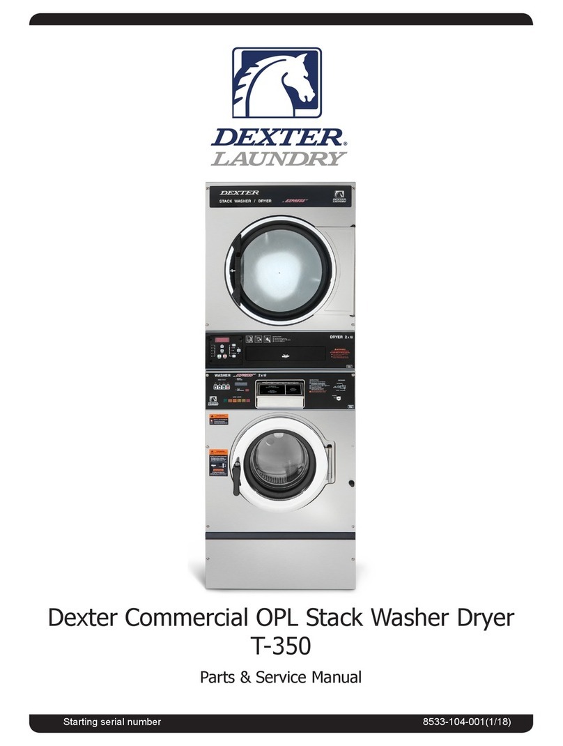
Dexter Commercial A-Series
Parts & Service Manual
Starting serial number 481983
A machine should not be allowed to
operated if any of the following occur:
• Excessively high water level.
• Machine is not connected to a properly grounded
circuit.
• Loading door does not remain securely locked
during the entire cycle.
• Vibration or shaking from an inadequate mounting or
foundation.
Table of Contents
Section 1:
Machine Mounting & Installation
T-300 .....................................................................6
T-400 & T-600.......................................................7
T-900 & T-1200......................................................8
T-300 Installation...................................................9
T-400 Installation.................................................10
T-600 Installation................................................. 11
T-900 Installation.................................................12
T-1200 Installation ...............................................13
Section 2:
Machine Installation & Operating Instructions
Basic Installation.................................................. 17
Electrical Connections & Fusing Requirements. . 18
Emergency Stop Button......................................19
Detergent Measurements by Model....................20
Machine Operating Instructions ................. 20 & 21
Section 3:
Machine Programming Instructions
Programming Instructions & Price Programming
............................................................. 24 & 25
Water Temperature Pricing ........................ 25 & 26
Wash Cycle
Programming.............................................. 26 & 27
Coin Washer Cycle Parameter Ranges ..............28
Coin Washer Default Cycle &
Rapid Advance Mode...................................29
Section 4:
Trouble Shooting
Common Troubleshooting Solutions Pages...32-36
Troubleshooting Machine Fault
Errors Pages ...........................................37-41
Variable Frequency Drive Control
Digital Readout Faults ..................................42
Section 5:
Machine Service Procedures
Coin Drop Acceptor.............................................44
Lower Service Panel Removal............................45
Dexter Safety
Guidelines
FOR SAFETY
Always shut off power and water supply 1.
and also discharge capacitors before
servicing.
Do not overload the washer.2.
Do not attempt to open door if cylinder 3.
is in motion or contains water.
Do not mechanically force or override 4.
door lock in any way.
Do not bypass any safety devices of 5.
this washer.
Do not use volatile or ammable 6.
substances in or near this washer.
Keep all panels in place. They protect 7.
against shock and injury and add
rigidity to the washer.
To activate your warranty, be sure to return
your red warranty form to the factory.
Please have serial number and model
ready when calling for assistance.
WARNING
These washers are equipped with devices and
features relating to their safe operation. To avoid
injury or electrical shock, do not perform and
service, unless qualied to do so.
2Part # 8533-053-001 REV 4/09

Top Panel Removal .............................................45
Front Panel Removal...........................................45
Back Panel Removal...........................................45
Drain Valve Access .............................................45
Drain Valve Cleaning...........................................46
Masking Ring (Door Lock Cover)
Removal ..............................................................46
Detergent Dispenser ...........................................46
Vaccuum Breaker/
Air Gap ................................................................46
Water Valves .......................................................46
Door Lock Assembly Operation..........................47
Adjustment for the Door Lock
Assembly.................................................... 47 & 48
Adjusting the Loading Door.................................49
Loading Door Removal .......................................49
Loading Door Hinge Removal.............................49
Loading Door Disassembly.................................50
Loading Door Reassembly..................................50
Control Panel Name Plate Decal ........................50
Name Plate Removal ..........................................50
Re-Installation of Name Plate .............................50
Outer Cabinet Removal....................................... 51
Door Locking Solenoid........................................52
Thermoactuators .................................................52
Lock Thermoactuator ..........................................52
Unlock Thermoactuator.......................................52
Drive Belt Removal..............................................52
Tub Back, Bearing and Cylinder Assembly.........53
Basket Pulley, Bearing Housing,
Water Seals & Tub Back ....................54 & 55
Drive Motor Removal...........................................56
T-300 Bolt Torque Chart......................................56
T-400, T-600, T-900 & T-1200 Bolt
Torque Chart ................................................57
Bearing Housing Assembly T-900 & T-1200.......58
T-900 & T-1200 Cylinder Basket Assembly ........59
Reassembly T-900 & T-1200 Cylinder................60
55 & 75 Pound Water Seals................................61
Outer Tub T-900 & T-1200...................................61
Section 6:
Machine Electrical & Wiring Schematics
Start Circuit..........................................................64
Fill Circuit.............................................................65
Wash Circuit ........................................................65
Drain, Rinse 1 & 2 & Final Rinse Circuit .............66
Extract Circuit......................................................66
Thermoactuator and Shake Out Circuit...............66
End of Cycle Circuit.............................................66
Control Mounting Trough.....................................66
Main Data Communication Cable.......................67
Circuit Breaker/Fuse............................................67
Main Control Printed Circuit Board......................67
PCB Transformer Step Down..............................67
Controls Transformer...........................................67
Main Relay Printed Circuit Board........................67
Pressure Switch ..................................................68
Power Connection Terminal Block......................68
LED Printed Circuit Board Temperature & Start/
Display Push Button.....................................68
Emergency Stop Button & Switch Assembly ......68
Add Bleach LED..................................................69
Delta Variable Frequency Drive ..........................69
Delta VFD Motor Leads.......................................69
Delta VFD Dynamic Braking
Resistors .............................................................69
Delta VFD Cooling Fan .......................................69
Coin Double Load 18 Pound
120 Volt Wiring Schematic ..................................70
Coin Double Load 18 Pound
120 Volt Wiring Diagram...............................71
IEC Double Load 18 Pound 120
Volt Wiring Schematic ..................................72
IEC Double Load 18 Pound
120 Volt Wiring Diagram...............................73
continued on next page
Coin Double Load 18 Pound 208-240 Volt Wiring
Schematic..................................................... 74
(continued on next page)
3
Part # 8533-053-001 REV 4/09
continued from previous page
Section 6:
Machine Electrical & Wiring Schematics
Coin Double Load 18 Pound
208-240 Volt Wiring Diagram .................... 75
IEC Double Load 18 Pound 208-240 Volt
Wiring Schematic ...................................... 76
IEC Double Load 18 Pound 208-240 Volt
Wiring Diagram ......................................... 77
Coin Triple Load 25 Pound Wiring Schematic.. 78
Coin Triple Load 25 Pound Wiring Diagram..... 79
IEC Triple Load 25 Pound Wiring Schematic ... 80
IEC Triple Load 25 Pound Wiring Diagram .......81
Coin Maxi Load 40 Pound Wiring Schematic... 82
Coin Maxi Load 40 Pound Wiring Diagram...... 83
IEC Maxi Load 40 Pound Wiring Schematic .... 84
IEC Maxi Load 40 Pound Wiring Diagram Page.. 85
Coin Mega Load 55 Pound Wiring Schematic.... 86
Coin Mega Load 55 Pound Wiring Diagram .... 87
IEC Mega Load 55 Pound Wiring Schematic... 88
IEC Mega Load 55 Pound Wiring Diagram...... 89
Coin Magnum Load 75 Pound
Wiring Schematic ...................................... 90
Coin Magnum Load 75 Pound Wiring Diagram... 91
IEC Magnum Load 75 Pound
Wiring Schematic ...................................... 92
IEC Magnum Load 75 Pound Wiring Diagram... 93
Schematic........................................................ 94
Section 7:
Parts Data
A-Series Accessories ...................................... 97
Cabinet and Front Panel Group Part #
by Model ...........................................98 & 99
Rear View Access Part # by Model .........100-101
Cylinder, Seals & Bearings Part #
by Model ....................................... 102 & 103
Door Lock Part # by Model.................. 104 & 105
Loading Door Part # by Model............. 106 & 107
Water Inlet Part # by Model ................. 108 & 109
Drain Valve Group Part # by Model ................110
Water Inlet Valve Breakdown Part # by Model.. 111
Wiring Harness Part # by Model.....................112
Labels and Diagrams All WCAD Models ........113
Chassis and Drain Part # by Model ......114 & 115
Control Panel Part # by Model.............. 116 & 117
Integrated Easy Card Control Panel Part #
by Model ........................................ 118 & 119
Electrical Components -
Top Compartment ..........................120 & 121
Coin Handling Group Part # by Model... 122 & 123
Section 8:
Maintenance
Preventative Maintenance...............................126
4Part # 8533-053-001 REV 4/09

5
Part # 8533-053-001 REV 4/09
Section 1:
Machine
Mounting
Drain Outlet
6”
3 7/8”
O
38”
Back
Water Inlet
OO
11 13/16”
8 13/32”
O
O
O
43 7/8”
15”
Front
20 7/8”
23 1/4”
*
**
* Alternate
** Recommended
26”
2 3/4”
2 1/2”
Drain Outlet
Side
16 3/4”
1 1/4”
14 5/16”
**
*
* Alternate
** Recommended
6”
25”
Specifications for below models
are outlined in this book:
T-300 WCAD 18KCS-10 120 V 60 Hz Phase 1
T-300 WCAD 18KCS-10 EC 120 V 60 Hz Phase 1 Easy Card
T-300 WCAD 18KCS-12 208-240 V 60 Hz Phase 1 & 3
T-300 WCAD 18KCS-12 EC 208-240 V 60 Hz Phase 1 & 3 Easy Card
T-400 WCAD 25KCS-12 208-240 V 60 Hz Phase 1 & 3
T-400 WCAD 25KCS-12 EC 208-240 V 60 Hz Phase 1 & 3 Easy Card
T-600 WCAD 40KCS-12 208-240 V 60 Hz Phase 1 & 3
T-600 WCAD 40KCS-12 EC 208-240 V 60 Hz Phase 1 & 3 Easy Card
T-900 WCAD 55KCS-12 208-240 V 60 Hz Phase 1 & 3
T-900 WCAD 55KCS-12 EC 208-240 V 60 Hz Phase 1 & 3 Easy Card
T-1200 WCAD 75KCS-12 208-240 V 60 Hz Phase 1 & 3
T-1200 WCAD 75KCS-12 EC 208-240 V 60 Hz Phase 1 & 3 Easy Card
T-300 Mounting Dimensions
6Part # 8533-053-001 REV 4/09
Drain Outlet
5”
6 1/8”
O
42 1/4”
Back
Water Inlet
OO
12 13/16”
9 13/32”
O
O
O
48”
16”
Front
26 7/8”
29 7/8”
2 3/4”
2 1/2”
Drain Outlet
Side
17 1/8”
1 1/4”
14 1/2”
**
*
* Alternate
** Recommended
4 5/8”
27 1/8”
Drain Outlet
5”
6 1/8”
O
44”
Back
Water Inlet
OO
12 13/16”
9 13/32”
O
O
O
49 3/4”
16”
Front
26 7/8”
29 7/8”
2 3/4”
2 3/4”
Drain Outlet
Side
21 1/2”
1 1/4”
5”
36”
T-400 Mounting Dimensions
T-600 Mounting Dimensions
7
Part # 8533-053-001 REV 4/09
Drain Outlet
7 1/2”
7 1/4”
O
49”
Back
Water Inlet
OO
11 13/16”
5 5/16”
O
O
O
54”
18 1/2”
Front
27 3/4”
34 3/8
2 3/4”
2 3/4”
Drain Outlet
Side
23”
1 1/4”
11 ”
7 1/2”
38 3/4”
T-900 Mounting Dimensions
T-1200 Mounting Dimensions
Drain Outlet
9”
7 1/4”
O
53 1/2”
Back
Water Inlet
OO
15 1/2”
13 1/2”
O
O
O
58”
20 1/2”
Front
34 3/8
2 3/4”
2 3/4”
Drain Outlet
Side
1 1/2”
7 1/2”
45 3/8”
50 1/2”
2”
7”
28 1/2”
12”
27 3/4”
8Part # 8533-053-001 REV 4/09
T-300 Mounting Dimensions
9
Part # 8533-053-001 REV 4/09
T-400 Mounting Dimensions
10 Part # 8533-053-001 REV 4/09

T-600 Mounting Pad Dimensions
11
Part # 8533-053-001 REV 4/09
T-900 Mounting Pad Dimensions
12 Part # 8533-053-001 REV 4/09
T-1200 Mounting Pad Dimensions
13
Part # 8533-053-001 REV 4/09
14 Part # 8533-053-001 REV 4/09
Notes

15
15
Part # 8533-053-001 REV 4/09
Section 2:
Machine
Installation
& Operating
Instructions
Installation & Operation
All washers must be installed in accordance with all local, state and national building, electrical, and
plumbing codes in effect in the area.
Foundation Requirements
The washer must be securely bolted to a substantial concrete oor, or mounted upon a suitable base
which is in turn securely bolted to a substantial concrete oor. Care must be stressed with all foundation
work to insure a stable unit, eliminating vibration. All installations must be made on sound concrete oors.
See mounting dimensions for each model being installed.
Mounting
A concrete pad or steel base which elevates the machine 4 to 6 inches above the oor level is
recommended to provide easy access to the loading door. Allow a minimum of 24” of clearance behind
the rear of the machine for service as is shown. Dexter highly recommends the use of a dry expansion
grout mix.
Proper Machine Grout Installation
Grout should be installed between base (if used) and concrete oor on all side rails and crossmembers. If
using a base you should grout between base top and machine frame and all side rails and crossmembers.
Mounting Holes
See mounting dimensions for the machine model you are installing in previous section. They also show
a typical concrete pad arrangement. It is highly recommended that you use all mounting holes supplied
with each model. Note: Mounting bolts should be checked frequently to insure that they remain tight. The
machine should be checked with a spinning load to be sure there is no unusual vibration or movement
between the machine and the base or oor. Please note: Machine grouting is highly recommended as
grouting insures stability and longevity.
Plumbing
Water supply hoses are furnished with each machine. The threaded connections on the hoses are
standard garden hose type thread. Separate hot and cold water lines with shut off valves or faucets for
inlet hose connections must be provided, maintaining 30 to 120 p.s.i. water ow pressure. Maximum water
temperature is 180 degrees.
Drain
The drain outlet tube at the rear of the machine is 3” in outside diameter on models T-400, T-600, T-900,
T-1200. A exible hose (# 9242-417-003) is available to extend the drain system for these models.
A drain outlet tube at the rear of the machine is 2 1/4” outside diameter on a T-300. model. A exible
hose ( #9242-417-001) is available to extend the drain system for these models. Adequate fall must be
maintained for proper drainage.
Protective Film
The machine may have protective adhesive lm on the front escutcheon area and the front and side
stainless steel panels. The lm may be peeled off before putting the machine into service.
Electrical
Dexter single/three-phase 208-240VAC 60 Hz washing machines are intended to be permanently installed
appliances. No power cord is provided. The machine should be connected to an individual branch circuit
not shared by lighting or other equipment. The connection should be sheathed in liquid tight exible
conduit, or equivalent, with conductors of the proper size and insulation. A qualied technician should
make such connections in accordance with the wiring diagram.
T-300 WCAD18KCS-10 model (1 phase 120 volts) washers are equipped with an electrical cord with a
3 prong grounded plug. A U.L. approved receptacle, which has been properly grounded in accordance
with local electrical codes must be used with the machine. Each unit should be connected to an individual
branch circuit not shared by lighting or other equipment. Conductors of the proper size and insulation (sug-
gested size below) should be used.
16 Part # 8533-053-001 REV 4/09
To Make Electrical Connections
Disconnect all power to the washer. Remove screw and lift out the cover located in the upper left corner
of the machine (as viewed from the back).
• If power is 208-240-3PH-60Hz, connect L1, L2, L3 and ground. If there is a high leg it must
be connected to L3. It is highly recommended to use a TVSS.
• If power is 208-240-1PH-60Hz, connect L1, L2 and Ground. If power is 120 -1PH-60Hz. Use
a UL approved receptacle with proper external ground.
NOTE: It is important that the grounding screw next to the power terminal
block TB-1 be connected to a good external ground.
Controls Transformer
The controls transformer is located inside the control trough and steps a range of 208 to 240 volts down
to 115 volts. There are two terminals on the controls transformer for the primary (incoming) power. Use
the terminal marked “208V” for power supplies between 200 and 215 volts. Use the terminal marked
“230V” for power supplies between 216 and 240 volts.
NOTE: transformer must be set at proper tap for proper operation.
Electrical Connections
Electrical power connections are made to the small terminal block located in the rear of the control
trough. The terminal block is accessed by opening the top panel of the machine.
• 1 Phase or 3 Phase connections
• 208-240 volts, 60 Hz.
• 3 wire plus ground
• Suggested Minimum Wire Size -- 12 Ga.
Fusing Requirements:
Dual element time delay fuse or equivalent breaker of amperage
specied below.
• 1 Phase or 3 Phase 15 amp
• WCAD-18-12,WCAD-25,WCAD-40
• 1 Phase or 3 Phase 20 amp
• WCAD-55, WCAD-75
• 1 Phase 20 amp
• WCAD-18-10 120 volt
Rotation in extract as viewed through glass door at front of
washer models WCAD-25,WCAD-40,WCAD-55,WCAD-75 will
be counter- clockwise.
Rotation in extract as viewed through glass door at front of
washer model WCAD-18 will be clockwise.
WARNING
Always disconnect electrical power to the
machine before performing any adjustments or
service.
17
Part # 8533-053-001 REV 4/09
Emergency Stop / Safety Door Lock
This machine is equipped with a Safety Door Lock that
locks the door closed from when the cycle is started
until the cycle is complete. The door lock prevents
opening the door for up to 3 minutes if the power is
interrupted during the cycle.
The Emergency Stop button pauses the washer and
allows the door to be opened during the cycle after
the Safety Door Lock releases. When the Emergency
Stop button is pressed an alarm will sound and the
display will begin counting down from “3”. If the button
is released before 3 seconds elapse, the alarm will stop
and the cycle will continue normally. If the Emergency
Stop is held down for 3 seconds, the display will
count down to “0” and the washer will begin stopping
movement and water ow and begin draining water from inside the washer. Though the machine may
stop wash movement quickly, it may take up to 3 minutes for the door to unlock. During that time the
alarm will continue to sound. When the alarm stops, the door may be opened. The washer may be
restarted by closing and latching the door, and pressing the Start button. If the washer was stopped
during nal extract, the cycle will be ended. If the washer is stopped for more than 1 hour, the cycle will be
terminated. If the emergency stop is triggered a second time during the cycle, the cycle will be terminated.
Operating Instructions
Microprocessor
Prior to operation, the micro computer should be set to display the amount of vend price being offered and
the cycle to be given to the user. NOTE: Should a power loss occur during cycle and when power returns,
P U S H will be displayed in window and customer must push the START button to continue the cycle.
Starting the Washer
A. Load the clothes loosely in the cylinder and latch the door securely. Be sure clothing does not get
caught between the door gasket and tub front when closing the door.
B. Pour low-sudsing powdered detergent in the amount shown below into the detergent dispenser on
top of the machine. Rinse conditioners may also be added to the dispenser. The correct location is
shown on the dispenser lid.
NOTE: To close the door the handle must be in the horizontal position and
then moved to the vertical position . After moving the door to the closed
position, the handle must be turned down to the vertical position to latch
the door for machine operation.
C .Using the TEMPERATURE SELECT buttons on the front, select the desired temperature.
If temperature pricing is being used you will display price changes as you push the desired
temperature selection.
This selection must be made before inserting coins to satisfy temperature price selected.If coins
or value are added after extended plus cycle vend price is met it will be lost without credit. If water
temperature pricing feature is active and vend price met and machine started the customer may
change temperature selections of equal to or lower priced temperature selections already inserted
into machine.
18 Part # 8533-053-001 REV 4/09

D. Insert coins, tokens or activate card reader to meet
displayed vending price. The washer will start, the
display will read PUSH and the green “on” led will
glow. The green start pushbutton must be pushed to
start cycle time countdown and machine starting to
run. “Door” will display if loading door is not closed
and handle locked.
E. If utilizing ADD PLUS CYCLE $.ooo option
The front display will scroll, ADD PLUS CYCLE
.25(example),amount to be added. User will have
1 minute to insert proper amount to activate this
option.
F. At the correct time in the wash bath cycle the green
“ADD BLEACH” light will come on indicating the
time and showing a diagram of the location for
adding bleach if desired. The timing is 2 1/2 minutes
after start of wash bath the light will come on and
stay on for 2 1/2 minutes or end of wash bath .
End of Cycle
When the cycle is completed, the end of cycle buzzer will
sound and the “on” light will go off. The loading door can
now be opened by turning the door handle to the indicated
position and pulling. Leave the clothes door open when the
machine is not in use. Also, at the end of cycle the display
will reset to the original amount required to start.
Detergent
Measurements By
Washer Model
Use 1/4
Cup
Use 1/4
Cup
Use 1/3
Cup
Use 1/2
Cup
Use 1/2
Cup
Double Load T-300 Washer
Triple Load T-400 Washer
Maxi Load T-600 Washer
Mega Load T-900 Washer
Magnum Load T-1200 Washer
19
Part # 8533-053-001 REV 4/09
20 Part # 8533-053-001 REV 4/09
Notes

21
Part # 8533-053-001 REV 4/09
Section 3:
Machine
Programming
Instructions
22 Part # 8533-053-001 REV 4/09
Programming Instructions
Programming can be accomplished manually using the machine
controls or by connecting to the machine control using a PDA
(personal digital assistant). For instructions on using a PDA with this
washer control, please contact your local Dexter distributor. Please
read below for manual programming instructions.
The washer has two levels of programming. The Washer Cycle
Programming allows the owner complete access to the wash cycle
parameters: add/remove a bath, bath times, spin times, water
temperatures, etc. The Coin/Price Programming allows the owner to
set the price for the washer features and the values of the coins. To enter the programming modes, the top
of the washer must be unlocked and slid toward the back of the washer a few inches.
Coin Price Programming
While the washer is in the Idle mode, push the Programming pushbutton on the controller. The Idle
mode is when the washer is not running a cycle and the price of the bath is displayed. The Programming
pushbutton is a very small buttoned located on the upper center of the controller directly behind the
display. There are seven stages in the Coin/Price Programming mode.
To step through to the desired stage, repeatedly push the Start button until the desired stage is blinking on
the display. To exit the Coin/Price programming mode, push and hold the Cold temperature button for 5
seconds.
#1 Right Coin: The display will blink rst an “r” indicating right coin and then a coin value ($1.00:
default). The display will blink back and forth between the “r” and the value. To change the value, use
the Hot temperature button to decrease and the Warm temperature button to increase. The value will
change in 1¢ steps. The range of values is from $00.00 to $99.99. When the desired right coin value
is displayed, push Start button once to store the new value and a second time to move to the next
Coin/Price programming step. To exit the Coin/Price programming mode, push the Cold temperature
button for 5 seconds.
#2 Left Coin: The display will blink rst a “L” indicating left coin and then a coin value ($0.25– default).
The display will blink back and forth between the “L” and the value. To change the value, use the
Hot temperature button to decrease and the Warm temperature button to increase. The value will
change in 1¢ steps. The range of values is from $00.00 to $99.99. When the desired left coin value is
displayed, push the Start button once to store the new value and a second time to move to the next
Coin/Price programming step. To exit the Coin/Price programming mode, push the Cold temperature
button for 5 seconds.
#3 Wash Price: The display will blink rst a “P” indicating wash price and then present wash price. The
display will blink back and forth between the “P” and the price. To change the value, use the Hot
temperature button to decrease and the Warm temperature button to increase. The value will change
in 1¢ steps. The range of values is from $00.00 to $99.99. When the desired price is displayed,
push the Start button once to store the new value and a second time to move to the next Coin/Price
programming step. To exit the Coin/Price programming mode, push the Cold temperature button for 5
seconds. FREE START can be set by dropping the wash price to $0.00.
Water Temperature Pricing
The washer can be set for different levels of pricing for Cold, Warm and Hot water. The Cold water setting
is considered as the base price, which is the normal washer cycle price.

23
Part # 8533-053-001 REV 4/09
#4 Warm Water Price: The next step in the pricing program is to set the additional price for Warm water
usage. The display will blink rst “CH P” indicating cold/hot water mix price and then “00.00”. To
change the value, use the Hot temperature button to decrease and the Warm temperature button to
increase. The value will change in 1¢ steps. The range of values is from $00.00 to $99.99.
NOTE: To not use this feature, set the price to “00.00”.
When the desired price is displayed, push the Start button once to store the new value and a second
time to move to the next Coin/Price programming step. To exit the Coin/Price programming mode,
push the Cold temperature button for 5 seconds.
#5 Hot Water Price: The next step in the pricing program is to set the additional price for Hot water
usage. The display will blink rst “H P” indicating hot water price and then “00.00”. To change the
value, use the Hot temperature button to decrease and the Warm temperature button to increase. The
value will change in 1¢ steps. The range of values is from $00.00 to $99.99.
NOTE: To not use this feature, set the price to “00.00”.
When the desired price is displayed, push the Start button once to store the new value and a
second time to move to the next Coin/Price programming step. To exit the Coin/Price programming
mode, push the Cold temperature button for 5 seconds. The Coin/Price programming mode will
automatically exit and return to the Idle mode if no buttons are pushed for one minute.
#6 Plus Cycle Price: The next step in the programming sequence is the Plus Cycle feature. The Plus
Cycle adds three (3) minutes of wash time to the wash bath only. The controller can be programmed
to charge a fee for this or the feature can be turned off. The default setting is off ($0.00).
The display will blink rst a “PC P” indicating Plus Cycle price and then price (back and forth). To
change the value, use the Hot temperature button to decrease and the Warm temperature button to
increase. The value will change in 1¢ steps. The range of values is from $00.01 to $99.99. When the
desired price is displayed, push the Start button once to store the new value and a second time to
move to the next Coin/Price programming step. To exit the Coin/Price programming mode, push the
Cold temperature button for 5 seconds.
#7 Decimal Point: The next step in the programming sequence is the Decimal Point. The display will
blink“dP” and Default value is ON. The value “on” for enable or “off” for disable. Once a pushbutton
is pressed, the display will stop blinking and show the decimal point value. The decimal point value
will display and change with the Hot and Warm buttons. When desired value is reached press Start
button.
Wash Cycle Programming
To change a feature of the wash cycle, push and hold the Hot temperature button and then push the
programming pushbutton on the controller. The Washer mush be in the Idle mode to enter the Wash Cycle
Programming mode. When entering the cycle programming mode the Bleach LED will start to blink and
continue to blink as long as you are in the Cycle Programming mode. The display will show “C 0”. This is
the default cycle number.
NOTE: The washer can be returned to the factory default settings by holding the right Warm button
and then pressing the left Warm button. The display must show “C 0” to do this. When the cycle default
values are loaded, the washer will automatically exit the programming mode.
NOTE: The Wash Cycle programming mode will automatically exit and return to the Idle mode if no
buttons are pushed for one minute.
24 Part # 8533-053-001 REV 4/09
To change the washer cycle, push the Hot temperature button once. The display will change to “C 1”,
indicating cycle one is selected. The temperature buttons are used to make changes to the program. In
the program mode, these buttons will do as displayed in drawing below.
When the display shows “C 1”, push Enter. The display will show “b “ and the PreWash mode light will
blink. Use the Up/Down buttons to move to the bath that will be changed. As Up/Down buttons are
pushed, the next bath mode light turns on.
When the Up button is pushed, the lit bath mode changes from Prewash to Wash. With each additional
push of the Up button, the lit bath mode changes from left to right: Prewash, Wash, Rinse and Final Rinse.
As there are two possible Rinse bathes, for Rinse 1 the Rinse LED and the display changes to “b” in the
left digit and “r1” in the two right hand digits. For Rinse2, the display changes to “b” in the left digit and “r2”
in the two right hand digits. Note that the Spin light is not used. When the Down button is pushed, the lit
bath mode changes from Prewash to Final Rinse, etc.. There is a wrap around feature on the display in
both directions.When the desired bath mode light is on, push Start.
Bath Cycle Time
The selected bath LED begins to blink. The display shows the letters “ct” in the left two digits and the bath
cycle time in the right two digits. Again the up/down buttons change this value. The range is shown below.
If zero time is entered, then the bath will be skipped and the program will return to the bath selection.
When the desired cycle time is selected, push Start.
Bath Water Temperature
The display shows the letter “t” in the left digit and the letters “CC” appear in the right two digits. This is
the bath water temperature. The selection choices are shown below but for the coin washer the value is
defaulted to CC. As it is not selectable with a coin washer, the owner pushes Start to continue.
Bath Water Level
The display shows the letter “L” in the left digit and the letters “LO” appear in the right two digits. This is
the bath water level. The selection choices are shown below but for the coin washer the value is defaulted
to LO. As it is not selectable with a coin washer, the owner pushes Start to continue.
Bath Delay Fill
The display shows the letters “dF” in the left two digits and the letter “t” appears in the right digit. This is
the bath delay ll. The selections are “t” for decrementing bath time during the ll or “d” for delay the bath
time until water level is reached. When the desired selection is made, push Start.
Bath Spin
The display shows the letter “S” in the left digit and the bath spin time in the right two digits. Again the up/
down buttons change this value. The range is shown below. When the desired spin time is selected, push
Start. The display shows the letters “IS” in the left two digits and the injection selection appears in the right
digit. For the coin washer the default value is “0” and cannot be changed. Push COLD.
The display will show “b” and the bath LED lights will stop blinking. Again use the up/down buttons change
the bath selection. To exit the programming mode, push and hold COLD until price is displayed. The cycle
will be stored when exiting the programming mode.

Coin Washer Cycle Parameter Ranges
The range of each cycle parameter is shown below:
Bath Cycle Time “ct”
0 to 15 minutes for Prewash, Rinse1 and Rinse 3 to 15 minutes for Wash and Final Rinse. For the baths
that can, if the time is set to zero, then that bath will be eliminated from the cycle.
Bath Water Temperature “t”
HH – hot, CH – warm, CC – cold, EE – no water. The owner can set the bath default. For the wash
bath, the default is over ridden for that cycle by the customer when the temperature is selected.
Bath Water Level “L”
LO – low The owner can change the displayed value, but for a coinwasher only LO will be put into the
cycle.
Bath Delay Fill “dF”
The selections are “d” for delay the bath time until water level is reached or “t” for decrement bath time
during the ll.
Bath Spin Time “S”
0 to 10 minutes for Prewash, Wash, Rinse1 and Rinse2 1 to 10 minutes for Final Spin.
Bath “IS”
The owner can change the displayed value, but for a coin washer only 0 will be put into the cycle.
25
Part # 8533-053-001 REV 4/09
Coin Washer Default Cycle (Preset at Factory)
The following table shows the complete details for the coin washer default cycle.
Bath Bath Cycle Time (min.) Water Temp. Water Level* Delay Fill Spin Time (min.) IS *
Prewash 0
Wash 9 CH LO t 0
Rinse 1 4 CC LO t 0 0
Rinse 2 0
Final Rinse 5 CC LO t 4 0
*NOTE: These default values are preset and cannot be changed.
Rapid Advance Mode
To enter the Rapid Advance mode, push and hold the Cold water temperature button and then push the
programming button on the controller. There will be no observed change to the washer or the display. The
Rapid Advance mode can be entered from either the Idle mode or during the cycle. To rapid advance to
the next step in the wash cycle, push both Start and Warm temperature buttons at the same time. The
display will show an “Ad” (advance) in the display. The washer will advance to the next bath segment. The
water will drain before the advance will occur.
To exit the Rapid Advance mode, push and hold the Cold temperature button for 5 seconds or more.
NOTES:
Step 1: When the Rapid Advance mode is used, the cycle time will no longer be correct.
Step 2: By skipping steps with rapid advance, the door may not open immediately at the end of the
cycle.
Main Control Printed Circuit Board
This control has a battery that allows memory retention in case of main power loss. The battery may need
replacing if time of day options are not functioning properly.
Remove power from machine and lockout safely.
Remove battery from socket on circuit board and reinstall new battery (#8612-001-001).
CAUTION: Do not soft reset this machine when installing new battery. This will
reset internal clock and not allow re-startup of internal clock, possibly causing programming
trouble.
26 Part # 8533-053-001 REV 4/09

27
Part # 8533-053-001 REV 4/09
Section 4:
Trouble
Shooting
Symptom Probable Cause Suggested Remedy
Machine
does not start
Power Supply Check these areas: Circuit breakers, Voltage, Power leads, Power
connections. Is front display LED showing a dollar amount.
Door Switch Check for continuity through door switch when door is closed. If no
continuity, adjust or replace door switch.
Control Breaker or
Fuse
Check 1.5 amp (T-1200. uses 2.5amp) breaker or fuse for continuity.
If no continuity, replace breaker or fuse.
Control Transformer Check voltage output from control transformer for 120VAC. If volt-
age is incorrect, replace transformer.
Coin Acceptor Check coin switch to make sure coins trip switch and give continuity
across switch when closed. If no continuity, adjust or replace switch.
Check PCB board Check all wire connections for sure contacts.
Check wiring be-
tween PCB
Check data cable phone type connectors unplug and VFD and
replug with power removed.
Check Relay PCB Check all wire connections for sure contact.
Check Door Solenoid Check that 120 v power is at solenoid after start button is pushed.
Machine will
not accept
and count
coins
Coin Acceptor Check coin acceptor switch for any type of blockage or damage.
Clean, adjust or replace the acceptor.
Power Supply Check these areas: Circuit breakers, Voltage,Power leads, Power
connection
Door Closed Safety
Switch
Check door closed switch at door hinge for proper operation.
Door Handle Closed
Switch
Check single door closed switch at left side of door handle to close
when handle is vertical.
Control Breaker or
fuse
Check 1.5 amp (T-1200 uses 2.5 amp) breaker or fuse for continuity.
If no continuity, replace breaker.
Main PCB Replace
Door does
not lock
Check display for
fault code
Does F1 show on the front of display. If yes follow tests described in
fault code section.
Door locking sole-
noid
Check to insure that solenoid is receiving 120VAC from main relay
PCB. If it is, replace solenoid.
Door Switch Check for continuity through door latch switch when door closed. If
no continuity, adjust or replace door switch.
Door will not
open
Thermoactuator Check to see if thermoactuator(s) and/or its mechanism is stuck or
binding and not allowing the door lock solenoid to open. Check to
be sure that the locking thermoactuator is not receiving 120VAC
during the last 1 1/2 minutes of the cycle. Also check to see that
the unlocking thermoactuator is receiving 120VAC during the last
minute of the cycle. If the thermoactuators do not receive voltage
at the correct times, change the timer. If the timing and voltage are
correct, replace the thermoactuator.
28 Part # 8533-053-001 REV 4/09
Common Troubleshooting Solutions

Symptom Probable Cause Suggested Remedy
Door will not
open
Door Rod Check to see that door rod from solenoid to lock ass’y is long
enough to allow lock ass’y to disengage. If not, adjust rod.
Door Lock Solenoid Check that door lock solenoid is not stuck closed. If stuck, replace
solenoid.
No hot water
in detergent
dispenser
Water Valve Coil Check coil continuity at terminals and replace if no continuity. 120 V
power only on for 20 second in wash bath.
Water Inlet Check water inlet screens for blockage and clean screens if neces-
sary.
Water Check to insure that water is turned on and operating.
P-20 Wire Harness Check black & white harness.
Symptom Probable Cause Suggested Remedy
Hot water
does not
enter tub in
wash
Water Valve Coil Check coil continuity at terminals and replace if no continuity.
Check for 120 V power from main relay PCB
Water Inlet Check water inlet screens for blockage and clean if necessary
screens
Water Check to insure that water is turned on and operating.
Blk or Wht wire at
main controller
Check black or white wires at Molex plug on PCB at main controller
and at relay PCB.
Pressure Switch Check pressure switch continuity between terminals . If no continu-
ity, check pressure switch hose for obstruction. If hose okay, change
pressure switch.
No cold water
to tub in wash
Water Valve Coil Check coil continuity at terminals and replace if no continuity.
Water Inlet Screens Check water inlet screens for blockage and clean if necessary.
Water Check to insure that water is turned on and operating.
Blk or whit wire at
controller and main
relay PCB
Check black or white wires at Molex plug on PCB at main controller
and at relay PCB.
Pressure Switch Check pressure switch continuity between terminal contacts. If no
continuity, check pressure switch hose for obstruction. If hose okay,
change pressure switch.
Water comes
in but level
does not rise
Drain Valve (open) Check these areas • Drain valve blockage • Drain valve motor and
gear train. If power but drain valve does not close, replace valve. •
Power to the drain valve. If no power to drain valve, check (brn/yel)
circuit for power.
Blk or whit wire at
controller
Check black and white wires at molex plug on main PCB controller
and at main relay PCB
Water does
not ush
softener com-
partment.
Water Valve Coil Check coil continuity at terminals and replace if no continuity.
Water Inlet Screens Check water inlet screens for blockage and clean if necessary.
Water Check to insure that water is turned on and operating.
29
Part # 8533-053-001 REV 4/09
Symptom Probable Cause Suggested Remedy
Water does
not ush
softener com-
partment.
Pressure Switch Check pressure switch continuity between terminals. If no continuity,
check pressure switch hose for obstruction. If hose okay, change
pressure switch.
Water level
too high
Pressure Switch Check for blockage in pressure switch hose. Check for pressure
switch opening circuit across terminals . Replace switch if contacts
do not open.
Water drains
slowly
Drain System Check hoses and drain valve for blockage. Clean of inadequate
size. if necessary. Check building drains for blockage
Machine
does not turn
VFD Check VFD by removing inspection panel and record any num-
bers or letters displayed. If no display turn power off to machine at
breaker for 2 minutes and turn poiwer back on to reset. If still no
display replace VFD
Machine
tumbles in
one direction
VFD Remove inspection cover at rear and record in only numbers or let-
ters displayed. See fault code section for more info.
VFD Inspect yellow enable wires from main relay PCB and at VFD
Excessive
vibration
Mounting System Check these areas: • Strength of mounting structure, concrete or
base. • Mounting bolts may be loose and need tightening.
Drive Belt Worn drive belt can cause vibration and noise.
Loading Note: Small loads contribute to out of balance loading and increase
vibration.
Machine
does not spin
Pressure Switch Check pressure switch for continuity across terminals #21 & #22
indicating pressure switch has reset to the empty position. If no
continuity, change pressure switch.
Machine
starts and
does not
operate
VFD Check yellow enable wires from relay PCB P13 & motor P14to VFD
advances through cycle are connected. Check fault code on VFD
before removing power from the drive. Check orange P-15 wire for
signal from door switches.
Machine
does not stop
Main PCB Main PCB controls time cycle at end of cycle
Braking Resistors Check braking resistors for continuity. Verify ohms resistance by
Molex.
Water leak-
age around
loading door
Door Adjustment Door may need adjustment due to abuse or wear. Check tightness
around perimeter using a dollar bill. Adjust left to right tightness by
shims at door lock or hinge side. It is important to center gasket to
tub opening before tightening door to hinge bolts. Chalk may be
used on tub front to show point of contact with tub. If gasket is de-
formed, worn, or damaged, replace. Refer to parts section for door
gasket expander kit.
30 Part # 8533-053-001 REV 4/09
Common Troubleshooting Solutions

Troubleshooting Machine Fault Errors
Displayed on front of washer
The following pages are a description of fault codes that will appear on the front of the washer. There is
a chart format that shows what fault code that will be displayed at washer front. These codes displayed
may stop machine operation or may not stop machine Please check chart before removing power to
reset. PLEASE NOTE: CHECK DRIVE FAULT CODE BEFORE POWERING MACHINE DOWN!
Fault# Description Customer Action
F1 The door failed to close and
lock or The door failed to remain
locked during the cycle.
Check VFD fault code before turning off. Check to hear if
door solonoid engaged. Turn off the power to the washer.
Check wire connections to door /lock switches. Check
wire connections from switches to controller. Check P-4
wire connections at PCB controller. Adjust the door lock
mechanism. (See service manual)
F2 The washer tub does not ll
with water within 7 minutes. The
wash cycle will continue. The F
2 will ash three times, then wait
for 30 seconds. The error will
clear at the end of the cycle.
Turn off the power to the washer. Check the operation of the
water valves. Check the incoming water pressure. Check for
blocked or restricted water ow. Check to ensure the drain
valve is functioning properly. This error will occur on 18#
washers when water level is set for high (the pressure switch
in 18# washer is only one level).
F3 Memory error in controller. The
memory checksum is wrong.
Check VFD fault code before turning off power. Try to clear the
fault with the Palm. Try a soft Reset of the controller with the
white button. If problem. Replace PCB controller.
F4 Washer controller
communication error
Check VFD fault code before turning off power. Try the data
cable rst. Move around cable and remove any side loading
tension from data cable connector ends. Check connection
P25/24/23 to P15. Turn power back on to the washer. If the
problem returns, replace the PCB washer controller.
F5 Pressure Switch error (only
OPL) - when the high level
sensor indicates full but the
lower one indicates empty. The
wash cycle will continue. The
F 5 will ash three times, then
wait for 30 seconds. The error
will clear at the end of the cycle.
Check VFD fault code before turning off power. Check the
pressure switch.(Ohm out contacts). Check pressure switch
connections to ensure they are all making good contact.
Check the Molex type harness connector to ensure no wire
been pushed out of the Molex type housing that it is shorting
or not connecting.
F6 Wrong washer size for drive
type.
Check VFD fault code before turning off power. If the controller
was installed in a different size machine before being installed
in this machine, a problem can occur. If someone has been
doing repairs on the washer, check for the correct size drive.
It can also be caused by pressure switch harness. Check
to ensure the correct harness in installed. The control can
be reset by holding program button on controller during
startup (soft reset). Check orange wire at Molex connector on
controller coming from pressure switch or replace pressure
switch harness.
31
Part # 8533-053-001 REV 4/09
Fault# Description Customer Action
F7 Wrong size drive installed Check VFD fault code before turning off power.Check to
ensure all the harnesses are properly connected to the
controller. Check to ensure the VFD drive horsepower is
proper for this size of washer. The control can be reset by
holding program button on controller during startup (soft reset)
Check orange wires at molex connector on controller coming
from pressure switch.
F8 The washer tub does not empty
within 7 minutes. The wash
cycle will continue. The F 8 will
ash three times, then wait for
30 seconds. The error will clear
at the end of the cycle.
Check VFD fault code before turning off power. Check to
ensure the drain valve is operating properly (slow drain has
potential to cause this code). Check to ensure the pressure
switch tube is clear of any blockage, and the pressure switch
is operating properly. Check the pressure switch harness.
F9 The washer tub does not reach
the spin target frequency within
150 seconds. The wash cycle
will continue. The F9 will ash
three times, then wait for 30
seconds. The error will clear at
the end of the cycle.
Check VFD fault code before turning off power. Check to
ensure the drain valve is operating properly (slow drain has
potential to cause this code). Check to ensure the pressure
switch tube is clear of any blockage, and the pressure switch
is operating properly. Check the pressure switch harness.
F10 After a spin the washer tub does
not stop within 150 seconds.
Check VFD fault code before turning off power. Inspect
the braking resistors and measure the resistance. Check
connecting wiring from braking resistor to the drive mounted in
the top of the washer. Reset the drive and try again. Possibly
incorrectly programmed drive.
F11 The drive size setting has
changed.
Check VFD fault code before turning off power. Check to
ensure all the harnesses are properly connected to the
controller. Check to ensure the drive horsepower is proper
for this size of washer. If no one has worked on machine very
recently then PCB controller or VFD may need to be replaced.
Do a soft reset before and after either VFD replaced.
F12 Washer controller internal error Check VFD fault code before turning off power. Turn off the
power to the washer. Wait one to two minute. Turn on the
power to the washer. If problem reappears, contact your
Dexter Authorized Representative.
32 Part # 8533-053-001 REV 4/09

Fault# Description Customer Action
F13 The variable frequency drive
(VFD) and the washer computer
are not communicating.
Check the data communication cable between the washer
computer and the variable frequency drive (VFD).
Step 1: Make sure the cable did not become unplugged during
operation.
Step 2: Make sure that the cable is not being pulled sideways
at either the washer controller, or the VFD, plug end. If
both ends of the communications cable are plugged in the
washer computer and VFD and there is no tension on the
communications cable pulling it from side to side, then replace
the cable.\
Step 3: Inspect both female connection points at PCB
controller and at VFD. These may need replacement if they
cannot be reset.
F14 Over-current on the drive or
motor. Step 1: Check to make sure the washer cylinder turns freely
by hand. If it turns freely, continue to step 2. If it does not,
remove the belt and see if the motor turns freely by hand.
If the motor turns freely, then check for obstructions in the
cylinder or check the bearings. If the motor does not turn
freely, replace the motor.
Step 2: Check the motor wires for a short circuit between
leads. If there are motor leads that have conductors touching,
separate them and insulate them. If the wires are broken,
splice them together or replace the motor.
Step 3: Check braking resistors to see if they measure the
correct resistance. If a resistor does not measure the proper
value, replace it.
F15 The variable frequency drive
(VFD) senses that the internal
voltage is too high. The source
of the problem can originate
from two different areas. Area
1: The input voltage can be too
high, or there may be a high
level of electrical noise. Area 2:
The motor can be generating
a voltage that is acting like an
input to the VFD output motor
terminals.
Step 1: Measure the supply voltage to the VFD on the L1, L2
(or N), and L3 (if connected to three phrase power). the supply
voltage should be from 187 to 264 VAC or 108 to 132 VAC for
a 120 VAC VFD. Also make sure the supply wires on L1, L2
(or N) and L3 (if connected to three phase power are securely
connected.
Step 2: Check the braking resistor connections at the VFD.
The terminal screws should be tight. Once of the braking
resistor wires should be connected to terminal B2.
Step 3: Measure each braking resistor separately to make
sure they are the correct resistance. (200 for 1 and 2 Hp VFD
and 160 for 3 Hp VFD).
Step 4: If you have a 240 VAC, high leg voltage supply, try
disconnecting the high leg. If this cures the problem, either
leave the high leg disconnected, connect a transient voltage
surge suppressor (with some form of ltering) at the voltage
supply panel, connect a line choke on the high leg or install a
VFD lter.
33
Part # 8533-053-001 REV 4/09
Fault# Description Customer Action
F16 The temperature sensor inside
of the variable frequency
drive detects that the internal
temperature is too high.
Step 1: Make sure the cooling ns on the VFD heatsink and
the ventilation louvers on the VFD cooling fan cover are clean.
Step 2: Start a washer cycle and make sure the VFD cooling
fan operates after the cylinder starts turning.
F17 Overload of the drive or motor (Check drive fault code before powering down). Check the
washer motor to ensure it turns freely. Check the wiring for
loose connections to the drive and motor. Measure the braking
resistor values. Check for damaged motor wires. Check V-Belt
tension and adjust to 1” deection at center. Check braking
resistors.
F18 Ground Fault to the drive Check VFD fault code before turning off power. Check the
wiring connections to the drive and motor. Check the ground
wiring of the drive, motor and incoming connection to ensure a
proper ground is present. Check for damaged motor wires.
F19 Low Voltage to the drive Check VFD fault code before turning off power. Turn the
power off to the washer. Check the wiring connections to the
drive and motor. If no problem is observed, turn on power to
the washer and test. (See Note) Measure the incoming line
voltage.
F20 Internal drive error Check VFD fault code before turning off power. Turn the
power off to the washer. Wait one minute. Turn the power
on to the washer. If problem reappears, contact your Dexter
representative.
F21 Data error on communications
between the controller and
drive Internal drive error #
32. This error also has CEXX
errors associated with it that are
presented on the drive display.
The CE errors are communications errors. Data Cable noise
can cause the majority of these errors.Check VFD fault code
before turning off power. Check the data cable between the
controller and the drive. Replace data cable if it appears
damaged and fault appears again. Please note that this fault
will occur if you turned main power off and on to quickly. (See
Note below)
Warning codes F22 - F28: These codes indicate that a component (VFD, relay PCB, in-
jection relay PCB, water valve) has been replaced, added, or removed and you will need
to soft reset the PCB controller board to reset the main controller to operate properly.
F22 Future use No action required
F23 VFD has been replaced,
disconnected, or removed.
Soft reset control.
F24 Injection relay PCB has been
removed or loose connection.
Soft reset control.
F25 Optional water valve PCB
removed or water valve has
been replaced .
Soft reset control.
F26 VFD unit has been added or
loose connection.
Soft reset control.
34 Part # 8533-053-001 REV 4/09

Fault# Description Customer Action
F27 Injection relay PCB has been
added to machine or loose
connection.
Soft reset control.
F28 Optional water valve PCB has
been added or loose connection
Soft reset control.
Note: Whenever power is turned off to the washer, it must remain off for three minutes for drive to reset.
The washer will not operate correctly if this is done improperly. This will allow most fault codes to reset
that are displayed at washer front. A fault code F-13 or F-21 will appear on front display if this procedure
has not been reset correctly. Note: Should a power loss occur during cycle and then power returns, P U
S H will be displayed and customer must push a temperature selection button to continue the cycle.
18lb A-Series Washer (both voltages 115/208-240)
Resistance
Motor Winding Wire # Minimum Maximum
18lb 1ph or 3ph 60hz Main (wash & spin) T1 & T2 3.91 4.6
Dexter #9376-307-001 T2 & T3 3.91 4.6
Marathon T1 & T3 3.91 4.6
25lb A-Series Washer
Resistance
Motor Winding Wire # Minimum Maximum
25lb 1ph or 3ph 60hz Main (wash & spin) T1 & T2 2.45 2.71
Dexter #9376-305-001 T2 & T3 2.45 2.71
A.O. Smith #19343600 T1 & T32.45 2.71
40lb A-Series Washer
Resistance
Motor Winding Wire # Minimum Maximum
40lb 1ph or 3ph 60hz Main (wash & spin) T1 & T2 2.45 2.71
Dexter #9376-305-001 T2 & T3 2.45 2.71
A.O. Smith #19343600 T1 & T3 2.45 2.71
55lb & 75lb A-Series Washer
Resistance
Motor Winding Wire # Minimum Maximum
55lb 1ph or 3ph 60hz Main (wash & spin) T1 & T2 2.4 2.8
Dexter #9376-308-001 T2 & T3 2.4 2.8
Marathon T1 & T3 2.4 2.8
NOTE: Resistance values are measured at the stator. Values at the end of the motor wiring
harness may be slightly higher.
Drive Motor Inverter Type
Motor-Winding Resistance Chart
35
Part # 8533-053-001 REV 4/09
Fault# Description Customer Action
CE1 VFD received an illegal
command. Possible controller
problem
Reset drive.
CE2 Illegal data address, VFD
received an address not
available to the controller.
Reset drive.
CE3 Illegal data value received
at VFD. Possible controller
problem.
Reset drive.
CE4 VFD unable to perform the
requested action. Possible
controller problem.
Reset drive.
CE6 Time frame between commands
is to short. Possible controller
problem.
Reset drive.
CE9 Internal checksum error. VFD
problem.
Reset drive.
CE10 Watch dog timer. Command
not received from the controller
every 6 seconds
Reset drive.
CE11 Frame error. Possible Baud
rate issues between VFD and
controller
Reset drive.
CE12 Command message is to short.
Possible controller problem
Reset drive.
CE13 Command message is to long.
Possible controller problem
Reset drive.
CE14 Command message includes
unused characters. Possible
controller problem.
Reset drive.
Normal operation of the VFD: VFD display shows operating frequency rst very quickly then changes
to F0.0 at time power is returned. This will stay displayed until the VFD receives a command from main
control PCB. (Pushing start button) A CE-10 fault will display at drive if improper communication between
PCB and VFD has occurred.
Note: Resetting a fault code on front of washer: Turn the power off to machine (machine will need to
remain off for up to three minutes ).
SOFT RESET : is accomplished by pushing the white button located on the Main controller PCB board and
simultaneously turning power on to machine. This will reset main controller to factory default settings.
Please record any modied information that has been inserted in memory before attempting to Soft Reset
the PCB.
CE5, CE7 and CE8—Reserved by DELTA
Variable Frequency Drive Control
Digital Readout Faults
36 Part # 8533-053-001 REV 4/09

Electrical Path Circuit Schematics
Start Circuit
Power travels into the machine on L1 & L2 & (L3, if 3 phase used). L1 and L2 provide 208- 240VAC to
the controls transformer which steps the voltage down to 120VAC for the controls. (The L1 connection
at the controls transformer must be checked at start-up to coincide with machine operating voltage) The
120VAC travels out from the transformer on either [X-1 red wire directly to the 1.5 amp fuse] or [X-1 black/
red wire to TB-4 and then through the red wire to the 1.5 amp fuse]. The controls transformer also cre-
ates a neutral on the X-2 black/blue wire that connects to TB-1. From the fuse holder, 120VAC travels on
the red wire to the #6 terminal on the terminal strip and then through the black wire to another step-down
transformer. From the terminal strip the blue wire will provide the neutral for solenoid, thermoactuators and
all valves. The white wire provides the neutral from the terminal to the step down transformer.
120VAC is stepped down to 2.3VAC (blue wires), 24VAC (red wires), and a yellow center tap wire to the
P-7 power connection on the main controller PCB . With the main control PCB now powered, 5VDC will
be present between the (2) yellow wires and also the (2) brown wires for the coin switches. Both pairs will
now be ready to count coins through the P-2 connection at the control PCB. 26.8 VAC goes out on the
black wire of the P-4 connection from the main control PCB to the S5 door closed switch which mounted
on the hinge side of masking ring. Closing the door will engage the door closed switches, sending the volt-
age to the red wire on the S1 door latched switch. Turning the door handle to the vertical latched position
closes the S1 door latched switch, returning the voltage to the main control PCB on the white/red wire at
the P-4 connection. 26.8VAC is now present at the S2 and S3 door locked switches.
26.8VDC is also at the black and white wires between P-21 at the main control PCB and the P-20 of the
relay PCB. This voltage signals the relay PCB that the door is closed and latched making 120VAC avail-
able to the relays controlling the door lock solenoid, drain valve and water valves. A continuous 5VDC
is sent on the red wire from the P-1 connector on the main control PCB, through the (normally closed)
emergency stop button switch and returns on the second red wire back to the P-1 connector. Payment is
added and the display counts down on the main control PCB display until the vend price is satised. The
display will change to read PUSH and the green light over the start button will ash. Pressing the start but-
ton on the front of the main control PCB signals the relay PCB to lock the door and 120VAC will go to the
door lock solenoid on the white/red wire from the P17 connector of the relay PCB. The door lock solenoid
engages and pulls up on the door locking rod, locking the door and closing the S2 and S3 door locking
switches.
The S2 locking switch is a backup to the S1 latching switch so that once the cycle starts the S1 isn’t criti-
cal. The S3 locking switch provides 26.8VDC on the orange wire back to P4 connector at the main control
PCB and the P15 connector at the relay PCB. This signals that the loading door is closed,locked and safe
to continue wash operations. This activates the P-13 and P-14 yellow enable wires to the inverter drive
to allow motion. If there is no signal on P-15 (orange wire) their will be no motion of the tub. S1, S2, S3
and S5 door switches are now closed . The green On LED and the door lock solenoid (discussed in start
circuit) will remain on throughout the cycle.
Fill Circuit-Warm
The relay PCB supplies 120VAC to the brown/yellow wire from P-17 to the drain valve which closes the
valve. The lock thermoactuator also receives 120VAC on orange/blue from P17 of the relay PCB. This
device prevents the door lock solenoid from dropping out and unlocking during the cycle in the event of a
power loss. The 120VAC will cycle on and off keeping the lock thermoactuator engaged until 70 seconds
before the end of the cycle. The main control PCB sends data commands to the VFD through the data
cable connected at P-6. These commands control the wash basket which will tumble one direction for 12
seconds, pause, and then reverse direction for 12 seconds.
37
Part # 8533-053-001 REV 4/09
The prewash or wash LED will illuminate at this time, powered through the white wires from the P-3 con-
nection of the main control PCB to the LED printed circuit board. Using the factory preset cycle as an
example: The washer lls the tub through the back of the machine with either one or both the C1 cold and
H1 hot water valves. From the P19 connection of main relay PCB, 120VAC is sent out on the white/brown
wire to the C1 cold water ll valve and the red/yellow wire to the H1 hot water ll valve depending on the
temperature selected. After a 90 second delay from the beginning of the wash cycle bath only, the deter-
gent dispenser ushes the detergent into the tub for 20 seconds. This is accomplished when 120VAC trav-
els through the red/orange wire to the H2 hot water valve solenoid. During the machine ll, a 5VDC signal
is sent on the red wire from the P5 connection of the main control PCB to the pressure switch contact and
returns on the yellow and orange wires to the P5 connection of the main control PCB. When the water
level in the basket reaches the preset level pressure, the switch moves the switch contacts to the full or
open position. This causes the main control PCB to signal the relay PCB to shut off the water valve coils.
Wash Circuit
Once the machine has achieved it’s water level, the wash basket will continue to tumble one direction for
12 seconds, pause, and then reverse direction for 12 seconds. The time on the front display will count
down as the bath progresses. The time of the bath is programmable up 15 minutes per bath. Note: When
programming cycles, the wash bath must be programmed for 3 minutes or more.
Drain
When the program bath time ends the main control PCB signals the relay PCB to remove 120 VAC power
from brown/yellow wire at P17 going to the drain valve. The normally-open, spring-loaded drain valve
opens allowing water to exit the machine. This resets the pressure switch back to an empty level and
restores the 5VDC connection through the pressure switch from the red wires to the orange and yellow
wires.
Rinse 1 & 2
For Rinse 1 & 2, the rinse LED will illuminate, the drain valve will receive 120VAC and close. The basket
will ll and tumble the same as the wash bath for the programmed time. The rinse water temperatures are
programmable and factory default is cold.
Final Rinse Circuit
The nal rinse LED will illuminate, the drain valve will receive 120VAC and close. The basket will ll and
tumble the same as the previous baths for the programmed time. The nal rinse water temperatures are
programmable. Note: When programming cycles, the nal rinse bath must be programmed and cannot
be set for less than 3 minutes. Also at the beginning of the nal rinse bath, the main control PCB will signal
the relay PCB to send 120V to the P-19 connector on the white/blue wire to the C2 cold water valve for 20
seconds to ush the fabric softener dispenser.
Spin Circuit
The spin LED will illuminate and the main control PCB sends a signal to the variable frequency drive via
the data cable at P6 to VFD RJ-11. The rotation as viewed from front during spin will be counter-clockwise.
(The 18lb washers will extract in a clockwise direction) The time of the spin cycle can be programmed.
Note: The nal spin must be programmed into the nal rinse bath and must be programmed for 1 minute
or more.
38 Part # 8533-053-001 REV 4/09

Unlock Thermoactuator and Shake Out Circuit
70 seconds before the end of the cycle the main control PCB signals the relay PCB to remove 120VAC
from the orange/blue wire at the P-17 connector on the lock thermoactuator. This allows the lock ther-
moactuator time to cool and retract by the end of the cycle. To insure that the lock thermoactuator has
retracted by the end of the cycle, 1 minute prior the end of the cycle, the unlock thermoactuator is powered
with 120VAC through the orange/red wire from the P-17 connector of relay PCB. The unlock thermoactua-
tor moves the complete bracket assembly away from the door lock solenoid allowing it to drop at the end
of the cycle. The basket will come to a stop from spin speed with the assistance of dynamic braking resis-
tors wired to the variable frequency drive. (See wiring diagrams for quantities and resistor ohm values).
The washer will then tumble for 45 seconds to let the clothes shake loose from the basket and then stop.
End of Cycle and Door Open Circuit
Once the machine stopped, 3 things occur: 1. The beeper will signal for 5 seconds letting the user know
that it is the end of the cycle. 2. The main control PCB signals the relay PCB to remove power from the
white/red wire at P-17 which allows the door lock solenoid to unlock. 3. The main control PCB resets when
the S1,S2,S3,S5 switches open and door is opened. The machine is now ready to accept coins again.
39
Part # 8533-053-001 REV 4/09
40 Part # 8533-053-001 REV 4/09
Notes
This manual suits for next models
17
Table of contents
Other Dexter Laundry Washer Dryer manuals

Dexter Laundry
Dexter Laundry T350 Quick start guide

Dexter Laundry
Dexter Laundry T450 Express User manual

Dexter Laundry
Dexter Laundry T-750 C4 Quick start guide

Dexter Laundry
Dexter Laundry WCAD-Series Quick start guide

Dexter Laundry
Dexter Laundry OPL Stack Express User manual

Dexter Laundry
Dexter Laundry C Series Quick start guide