Deye Spring Series User manual

User Manual
Spring series LFP Battery
SE-G5.1 Pro
V1.4

-1-
Read and follow these instructions!
The following precautions are intended to ensure your safety and prevent property damage. Before
installing this product, be sure to read all safety instructions in this document for proper installation.
Failure to comply with the instructions with this symbol may result in a
serious accident, causing death or a severe injury.
Failure to comply with the instructions with this symbol may result in a
serious accident, causing a severe injury.
Failure to comply with the instructions with this symbol may result in
minor or moderate injury.
Provides information considered important but not hazard-related. The
information relates to property damage.
Read instruction before use
Risk of electric shock
Operate as specified by the manual
This product is designed to an integrated system, which must be performed by a qualified person
trained in electrical engineering and familiar with the characteristics and safety requirements of
lithium batteries. Do not use this product if you are unsure if you possess the necessary skills to
complete this integration.

-2-
Table of Contents
1. Precautions................................................................................................................................... 3
1.1 General Safety Precautions........................................................................................................ 3
1.2 Installation Precautions............................................................................................................... 3
2. Product Introduction...................................................................................................................... 4
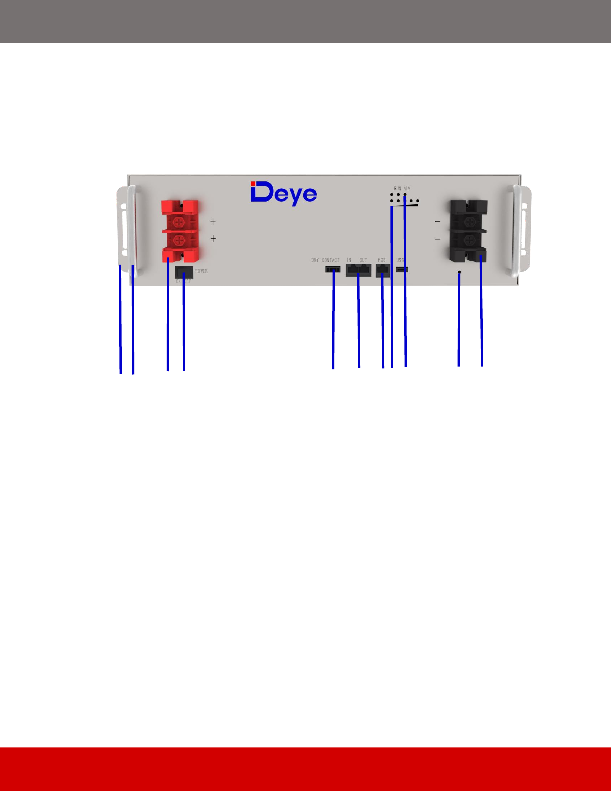
2.1. Front Panel Function Introduction.............................................................................................. 4
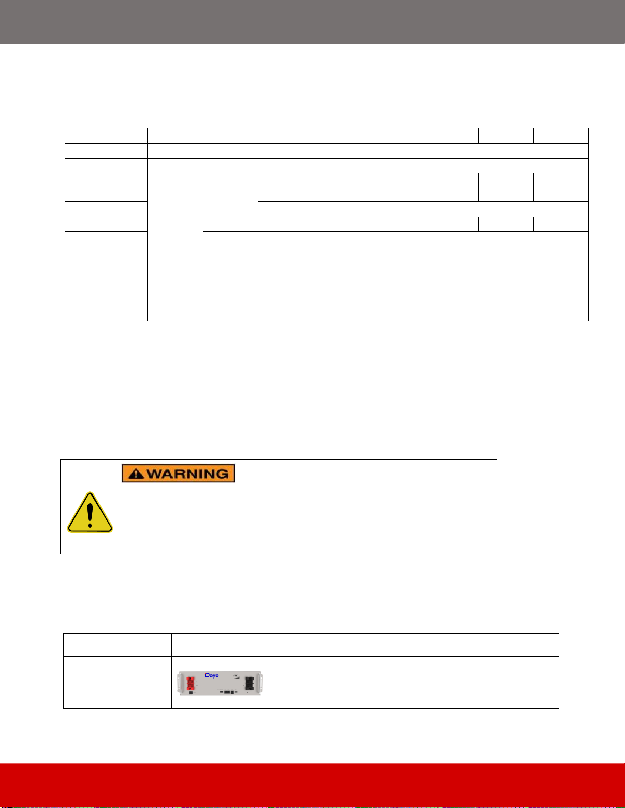
2.2 Product Specifications................................................................................................................ 6
2.3 State Indicator ............................................................................................................................ 7
3. Unpack the Battery ....................................................................................................................... 7
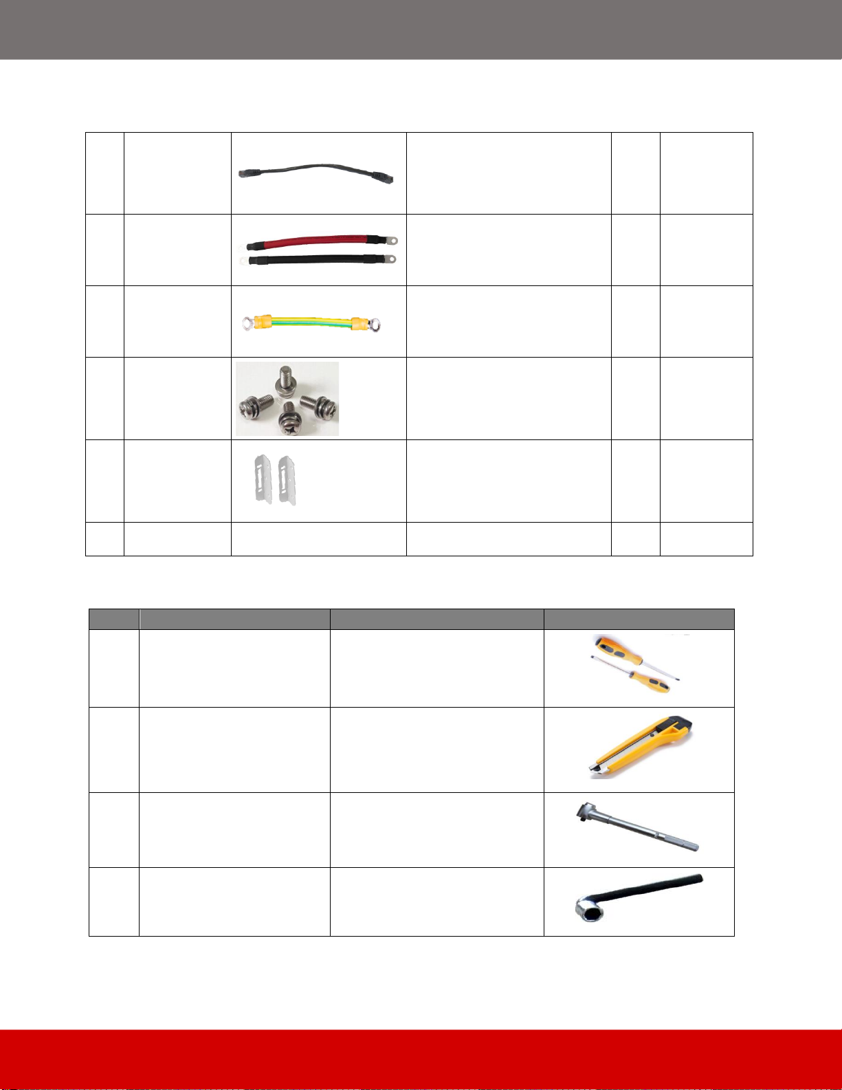
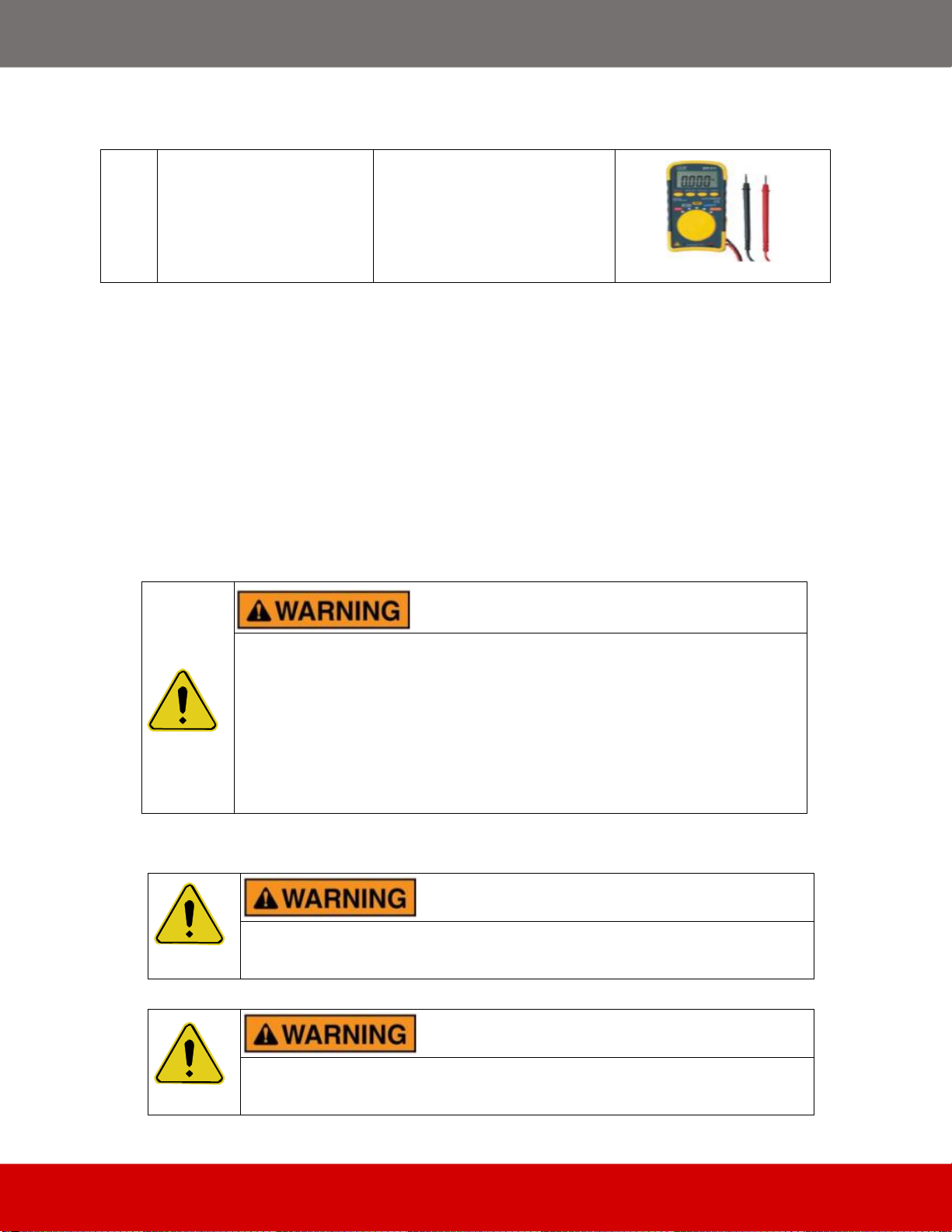
3.1 Parts List..................................................................................................................................... 7
3.2 Visual Inspection of the Modules................................................................................................ 9
4. Battery Installation............................................................................................................................ 9
4.1 Battery Module Installation ....................................................................................................... 10
5. Cable Connection........................................................................................................................... 11
5.1 Single Battery Connection.................................................................................................... 11
5.2 Connect Cables of the Multiple Batteries in Parallel................................................................. 14
5.3 Visual Inspection of the Connection ......................................................................................... 17
6. Activate the Product....................................................................................................................... 17
6.1 Start the Battery........................................................................................................................ 17
7. Inspection, Cleaning and Maintenance.......................................................................................... 17
7.1 General Information.................................................................................................................. 17
7.2 Inspection ................................................................................................................................. 18
7.3 Cleaning ................................................................................................................................... 18
7.4 Maintenance............................................................................................................................. 18
7.5 Storage..................................................................................................................................... 18
8. Troubleshooting ............................................................................................................................. 18
9. Firmware Update............................................................................................................................ 19
9.1 USB Upgrade ....................................................................................................................... 19
9.2 PC Upgrade.......................................................................................................................... 20
9.3 PCS Upgrade ....................................................................................................................... 23
10. Battery recovery........................................................................................................................... 25
10.1 Recovery process and steps of cathode materials................................................................. 25
10.2 Recovery of anode materials.................................................................................................. 26
10.3 Recovery of diaphragm........................................................................................................... 26
10.4 List of recycling equipment:.................................................................................................... 26
11. Transportation Requirements....................................................................................................... 26

-3-
1. Precautions
1.1 General Safety Precautions
The product provides a safe source of electrical energy when operated as intended and as designed.
Potentially hazardous circumstances such as excessive heat or electrolyte mist may occur under
improper operating conditions, damage, misuse and/or abuse. The following safety precautions and
the warning messages described in this part must be observed.
If any of the following precautions are not fully understood, or if you have any questions, contact us
for guidance.
Risks of explosion
Do not subject the battery to strong impacts.
Do not crush or puncture the battery.
Do not dispose of the battery in a fire.
Risks of fire
Do not expose the battery o temperatures in excess of 60℃.
Do not place the battery near a heat source such as a fireplace.
Do not expose the battery to direct sunlight.
Do not allow the battery connectors to touch conductive objects such as wires.
Risks of electric shock
Do not disassemble the battery.
Do not touch the battery with wet hands.
Do not expose the battery to moisture or liquids.
Keep the battery away from children and animals.
Risks of damage to the battery
Do not allow the battery to come into contact with liquids.
Do not subject the battery to high pressures.
1.2 Installation Precautions
Please be aware that a battery presents a risk of electrical shock including high short-circuit current.
Follow all safety precautions while operating the batteries.
Remove watches, rings, and other metallic accessories.
Use tools with insulated handles in order to avoid inadvertent short circuits.
Wear rubber gloves and safety boots.

-4-
Do not put tools or any metal parts on the top of the batteries.
Disconnect charging source and load before connecting or disconnecting terminals.
When moving batteries and wear all appropriate safety clothing and equipment.
Do not open or mutilate the batteries.
▪Verify polarity at all connections before energizing the system. Reverse
polarity at the battery terminals will void the Warranty and destroy the
batteries. Do not short circuit the batteries.
▪Do not combine Lithium Batteries with other brands or chemistries; Do
not mix Lithium Batteries from different installations, clients, or job sites.
▪Do not disassemble or modify the battery. If the battery housing is
damaged, do not touch exposed contents.
2. Product Introduction
48 V series lithium iron phosphate battery system has been designed to provide power backup for
remote or outside telecom plants like Access Terminals, Base Transceiver Stations, and Base
Station Controllers. This system has the characteristics of high system integration, well reliability,
long service life, and wide operating temperature range.
2.1. Front Panel Function Introduction
In order to operate the product correctly, please carefully view the function of the front panel of the
battery.

-5-
Figure 2-1: Front Panel Function Introduction
1. Power button:to turn ON/OFF the whole battery BMS standby, no power output.
2. DRY CONTACT output.
3. PCS:Inverter communication terminal: (RJ45 port) follow the CAN protocol (baud rate:
500kbps), and RS-485(baud rate: 9600bps),used to output battery information to the inverter.
4. IN:parallel Communication Terminal: (RJ45 port) Connect "out" Terminal of Previous battery , for
communication between multiple parallel batteries.
OUT:parallel Communication Terminal: (RJ45 port) Connect "IN" Terminal of Next battery, for
communication between multiple parallel batteries.
5. SOC:These 5 LEDs are used to display the pack SOC. The lightning of these LEDs indicates the
SOC of 20%, 40%, 60%,80% and 100%.
6. RUN light: green LED lighting to show the battery running status
Alarm light: red LED lighting to show the battery has been alarmed.
7. USB : (USB port) Used to insert USB flash drive for battery upgrade.
8. Negative output terminal.
9. Positive output terminal.
1
2
3
4
7
5
6
10
8
11
9
12

-6-
10.Grounding bolt.
11.Handle: It was used to carry/move the battery.
12.Used for fixing with cabinet.
2.2 Product Specifications
Table 2-1: Product Specifications
Main Parameter
SE-G5.1 Pro
Battery Chemistry
LiFePO4
Capacity (Ah)
100
Scalability
Max. 64 pcs pack (327kWh) in parallel (Max. 32 pcs no external setup)
Nominal Voltage (V)
51.2
Operating Voltage(V)
43.2~57.6
Energy (kWh)
5.12
Usable Energy (kWh)[1]
4.61
Charge/Discharge
Current (A)
Recommend[2]
50
Max.[2]
100
Peak(2mins,25℃)
150
Other Parameter
Recommend Depth of Discharge
90%
Dimension (W/H/D,mm)
445*133*430
Weight Approximate(kg)
44
Master LED indicator
5LED(SOC:20%~100%)
3LED (working, alarming, protecting)
IP Rating of enclosure
IP20
Working Temperature
Charge:0℃~55℃
Discharge:-20℃~55℃
Storage Temperature
0℃~35℃
Humidity
5%~95%
Altitude
≤2000m
Cycle Life
≥6000(25±2℃,0.5C/0.5C,70%EOL)
Installation
19-inch standard cabinet, cabinet depth ≥600mm / with rack
Communication Port
CAN2.0, RS485
Certification
UL1973, IEC62619, CE, UN38.3
[1] DC Usable Energy, test conditions: 90% DOD, 0.5C charge & discharge at 25°C. System usable energy may vary due to system configuration parameters.
[2] The current is affected by temperature and SOC.

-7-
2.3 State Indicator
Condition
RUN
ALR
ERROR
SOC1
SOC2
SOC3
SOC4
SOC5
Power Off
Off
Discharge or
Idle
Blink
Bilnk if
Alarm
Exists
Off
e.g. Soc67%:
Off
On
On
On
On
Charge
Off
e.g. Soc47%:
Off
Off
Blink
On
On
Alarm
Bilnk
Off
Same as 'Discharge or Idle'
System
Error/Protection
On
Upgrade
Blink Fastly
Critical Error
Blink Slowly
3. Unpack the Battery
The battery and the related accessories are packed in the carton box and steel belt wooden box. Use
tools to open the packing box. After open the packing box, confirm the product components
according to the parts list.
3.1 Parts List
Check the parts during unpacking.
Table 3-1: Parts Lists
No.
Items
Appearance
Usage
Qty.
Remarks
1
Battery
Provide power
1
Violent unpacking is strictly prohibited. If the battery system is found to be
broken, deformed or other abnormal conditions, the user shall immediately
stop using the battery and contact us.

-8-
2
RJ45
communication
line 300mm
Communication cable for
battery parallel
1
3
4AWG
Red&Black
Power line
300mm
Power cable for battery parallel
2
4
10AWG
yellow-green
ground line
300mm
Battery ground line
1
5
M6*16 Cabinet
bolt
Fix the battery on the rack or
cabinet
4
6
Battery Rack
Fixed Ears and
M4*8 bolt
Used for battery fixing with
19inch rack or cabinet
2 ears
6 bolts
7
User manual
/
/
1
Table 3-2: Recommended Tools andInstruments
No.
Items
Usage
Appearance
1
Phillips Screwdriver or Bit
Tofasten battery and
assemblies
2
Box Cutter
Opening boxes
3
Insulated TorqueWrench
Installing cables and busbars
4
Insulated Sockets
Installing cables and busbars

-9-
5
Battery Tester
Measure battery module’s
voltage
3.2 Visual Inspection of the Modules
After transporting the modules to the installation location, check for:
Physical damage to the exterior
Damaged or protruding screws
4. Battery Installation
This system must be installed by qualified, trained workers familiar with the required instruments.
▪Be sure to use insulated tools (torque wrench, extension, socket, etc.).
▪All the instruments must be insulated and no metal articles (e.g. watch,
ring) shouldbe present in the installation area.
▪All power switches must be turned off in advance.
▪Prepare a CO2 fire extinguisher, a first aid kit, and an AED (automated
external defibrillator) before installation.
Arc Flash and Shock Hazard
Insulated tools are required for any work on this energizedequipment.
Sharp Edges
Wear gloves and other protective gear to prevent injury.

-10-
Pinch Point
Use caution when working in the enclosure to prevent injury.
Heavy Object
Can cause muscle strain or back injury.
Use lifting aids and proper lifting techniques when moving trays, batteries
and otherheavy objects.
4.1 Battery Module Installation
1. Transport battery modules to the installation location.
3. Place the battery modules on the bracket or rack or cabinet.
4. Fix the battery on the bracket or rack. Using the bracket or cabinet bolt to fix the battery into the
bracket or rack.
5. After installation, tighten all bolts.
Figure 4-1: Battery Module Installation (A possible battery install procedure)

-11-
▪We recommends installing battery modules in the upper shelves first and
proceeding to the bottom.
▪The battery can be mounted on a standard 19 inches cabinet or rack.
▪Battery modules can be inserted into a rack frame according to the
customer battery configuration scheme.
5. Cable Connection
5.1 Single Battery Connection
▪Before connect the cable with the inverter, the worker must confirm the output
switch of the inverter has been turn off, to prevent the risk of fire or electric
shock.
▪Before connection, make sure to close the battery.
▪Please follow the instructions to protect the module BMS against damage.
▪DO NOT deviate from the sequence of steps below.
▪Exercise extreme caution prevent the terminals from contacting anything except
their intended mounting points.
▪Terminals and their connected wires have either positive or negative polarity
(Positive: +; Negative-). The polarity of a terminal or a wire connected to the
terminal is onthe front of each module. Exercise extreme caution to prevent the
terminals and/or wires with opposite polarity from contacting with each other.
▪The maximum voltage of the battery is no more than 60V, which is higher than
the safe voltage of 36V. Therefore, we still recommendthat the battery terminals
or other exposed parts should not be directly touched during the installation.

-12-
▪When tightening the screws, make sure they are at a straight angle from the
battery module terminals to avoid damage to the nuts inside.
▪Assemble the screws using a Phillips-head within the fasteningtorque of less
than 8.0 Nm (79.88 kgf/cm).
▪The power terminals, such as “+,” “-,” of the module are covered with the
protecting cover to guard against a short circuit (Shown in Figure 5-1).
▪You must remove the insulation cover prior to connecting and reattach the
insulation cover immediately after connecting.
Figure 5-1: Install the Grounding Wire
Step 1 Wear the protective gloves.
Step 2 Install the battery ground cable.

-13-
Step 3 Install negative and positive power cables for the battery.
1) Remove the protective cover from the battery power wiring terminal.
2) Connect the negative power cable to the battery.
3) Connect the positive power cable to the battery.
4) Install the other end of the battery power cables at a battery route and the corresponding RTN+
busbar in the power system.
5) Reinstall the protective cover on the battery power wiring terminals.
Connect the inverter:
1) Remove the protecting cover.
2) Take-down positive fixing bolt by the Phillips Screwdriver and connect the positive output cable
between the battery positive terminal of the battery and the inverter. After connecting the battery,
fastening bolt immediately to avoid dropping.
Figure 5-2: Single Battery Connection
3) Take-down negative fixing bolt by the Phillips Screwdriver and connect the negative output cable
between the battery negative terminal of the battery and the inverter. After connecting the battery,
fastening bolt immediately to avoid dropping.
4) Install the protecting cover.
5) Sort the cables and fasten the battery cables to the perforated bracket with cable ties.
6) Communication Line Connection
As shown in Figure 5-3, when monitoring the battery by the computer, connect the ‘USB convert to

-14-
RS485’ or CAN Box communication line between battery and computer.
Figure 5-3: Communication Cable Connections between Battery and Computer
5.2 Connect Cables of the Multiple Batteries in Parallel
When multiple batteries in parallel, the cable connecting procedures are follows.
5.2.1. As shown in Figure 5-4, following the cable connection method of the single battery, connect
the positive and negative cables between the Battery 1 and the busbar, Battery 2 and the busbar,
and Battery N and the busbar respectively.
Note: To ensure the current balance, please use cables with the same diameter and length for each
battery.

-15-
Figure 5-4: Multiple Batteries Connections
5.2.2. As shown in Figure 5-4, connect the communication line (a standard RJ45 network cable)
between the adjacent batteries.

-16-
5.2.3. Connect the communication line between battery and computer
(1) PCS Port Definition
(2) IN Port Definition
(3) OUT Port Definition

-17-
5.3 Visual Inspection of the Connection
After connecting the battery, check for:
Usage of positive and negative cables.
Connection of the positive and negative terminals.
All the bolts are tightened.
Cables fixation and the appearance.
The setting of the dialing address.
The installation of the protecting cover.
6. Activate the Product
6.1 Start the Battery
After installation, wiring, and configuration are completed, you must check all the connection. When
the connections are correctly, and then press power button to activate the battery. The green working
light on the front panel of the battery flashes, indicating that the battery system is normal.
7. Inspection, Cleaning and Maintenance
7.1 General Information
The battery product is not fully charged. It is recommended that the installation be completed
within 3 months after arrival;
During the maintenance process, do not re-install the battery in the battery product. Otherwise,
the performance of the battery will be reduced;
It is forbidden to dismantle any battery in the battery product, and it is forbidden to dissect the
battery;
After the battery product is over-discharged, it is recommended to charge the battery within 48
hours. The battery product can also be charged in parallel. After the battery product is
connected in parallel, the charger only needs to connect the output port of any product battery.
Never attempt to open or dismantle the battery! The inside of the battery does not contain
serviceable parts.
Disconnect the Li-Ion battery from all loads and charging devices before performing cleaning
and maintenance activities
Place the enclosed protective caps over the terminals before cleaning and maintenance

-18-
activities to avoid the risk of contacting the terminals.
7.2 Inspection
Inspect for loose and/or damaged wiring and contacts, cracks, deformations, leakage or
damage of any other kind. If damage to the battery is found, it must be replaced. Do not attempt
to charge or use a damaged battery. Do not touch the liquid from a ruptured battery.
Regularly check the battery’s state of charge. Lithium Iron Phosphate batteries will slowly self-
discharge when not in use or whilst in storage.
Consider replacing the battery with a new one if you note either of the following conditions:
- The battery run time drops below 80% of the original run time.
- The battery charge time increases significantly.
7.3 Cleaning
If necessary, clean the Li-Ion battery with a soft, dry cloth. Never use liquids, solvents, or abrasives
to clean the Li-Ion battery.
7.4 Maintenance
The Li-Ion battery is maintenance free. Charge the battery to approximately > 80% of its capacity at
least once every year to preserve the battery’s capacity.
7.5 Storage
The battery product should be stored in a dry, cool and cool environment;
Generally, the maximum storage period at room temperature is 6 months. When the battery is
stored over 6 months, it is recommended to check the battery voltage. If the voltage is higher
than 48V, it can continue to store the battery. In addition, it is needed to check the voltage at
least once a month until the voltage is lower than 48V. When the voltage of the battery is lower
than 48V, it must to be charged according to the charging strategy.
The charging strategy is as follows: discharge the battery to the cutoff voltage with 0.2C10A
current, and then charge with 0.2C10A current for about 3 hours. Keep the SOC of the battery
at 40-70% when stored;
When the battery product is stored, the source of ignition or high temperature should be avoided
and it should be kept away from explosive and flammable areas.
8. Troubleshooting
To determine the status of the battery system, users must use additional battery status monitoring

-19-
software to examine the protection mode. Refer to the installation manual about using the monitoring
software. Once the user knows the protection mode, refer to the following sections for solutions.
Table 8-1: Troubleshooting
Fault Type
Fault Generation
condition
Possible Causes
Troubleshooting
BMS fault
The cell voltage sampling
circuit is faulty.
The cell temperature
sampling circuit is faulty
The welding point for cell voltage
sampling is loose or disconnected.
The voltage sampling terminal is
disconnected.
The fuse in the voltage sampling circuit
is blown.
The cell temperature sensor has failed.
Replace the battery.
Electrochemical
cell fault
The voltage of the cell is low
or unbalanced.
Due to large self- discharge, the cell
over discharges to below 2.0V after
long term storage.
The cell is damaged by external
factors, and short circuits, pinpricks, or
crushing occur.
Replace the battery.
Overvoltage
protection
The cell voltage is greater
than 3.65 V in charging state.
The battery voltage is greater
than 58.4 V.
The busbar input voltage exceeds the
normal value.
Cells are not consistent. The capacity
of some cells deteriorates too fast or
the internal resistance of some cells is
too high.
If the battery cannot
be recovered due to
protection against
abnormality contact
local engineers to
rectify the fault.
Under voltage
protection
The battery voltage is less
than 40V.
The minimum cell voltage is
less than 2.5V
The mains power failure has lasted for
a long time.
Cells are not consistent. The capacity
of some cells deteriorates too fast or
the internal resistance of some cells is
too high.
Same as above.
Charge or dis-
charge high
temperature
protection
The maximum cell
temperature is greater than
60◦C
The battery ambient temperature is too
high.
There are abnormal heat sources
around
Same as above.
Charge low
temperature
protection
The minimum cell
temperature is less than 0◦C
The battery ambient temperature is too
low.
Same as above.
Discharge low
temperature
protection
The minimum cell
temperature is less than
-20◦C
The battery ambient temperature is too
low.
Same as above.
By checking the above data and sending the data to the service personnel of our company, the
service personnel of our company will reply the corresponding solution after receiving the data.
9. Firmware Update
9.1 USB Upgrade
USB only supports USB flash drives with FAT32 file system format.
Other manuals for Spring Series
2
This manual suits for next models
1
Table of contents
Other Deye Camera Accessories manuals