Deye Spring Series User manual
User Manual
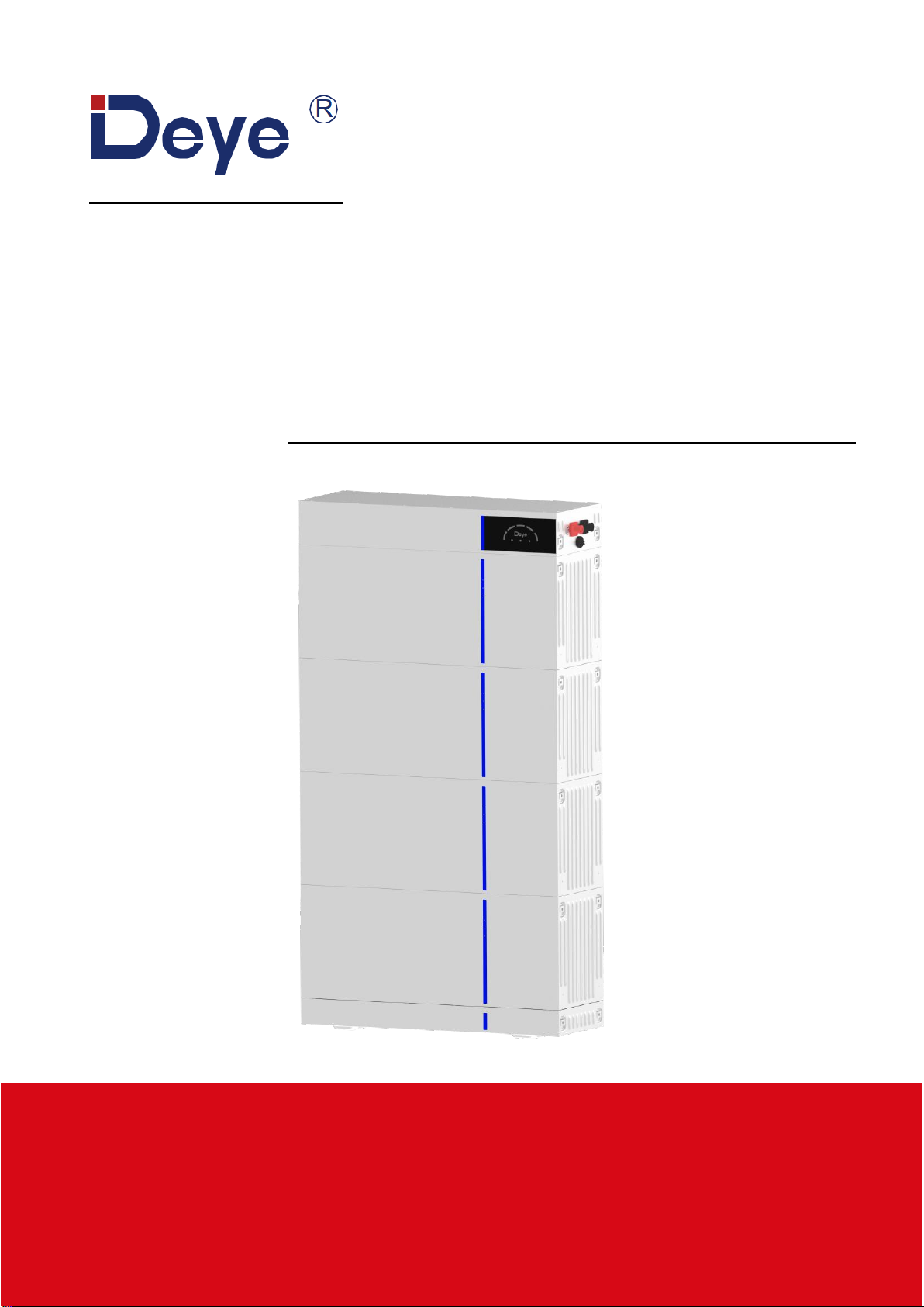
Spring series LFP Battery
AI-W5.1
V1.0

~ 1 ~
About This Manual
The manual mainly describes the product information, guidelines for installation, operation, and
maintenance. The manual cannot include complete information about the solar photovoltaic-
energy storage hybrid system.
How to Use This Manual
Read the manual and other related documents before performing any operation on the battery.
Documents must be stored carefully and be always available.
Contents may be periodically updated or revised due to product development. The infor-
mation in this manual is subject to change without notice. The latest manual can be acquired
1
Safety Introductions
Reminding
1)
It is very important and necessary to read the user manual carefully (in the accessories)
before installing or using battery. Failure to do so or to follow any of the instructions or
warnings in this document can result in electrical shock, serious injury, or death, or can
damage battery, potentially rendering it inoperable.
2)
If the battery is stored for long time, it is required to charge them every six months, and
the SOC should be no less than 50%.
3)
Battery needs to be recharged within 48 hours after fully discharged.
4)
Do not expose cable outside.
5)
All the battery terminals must be disconnected for maintenance.
6)
Please contact the supplier within 24 hours if there is something abnormal.
7)
Do not use cleaning solvents to clean battery.
8)
Do not expose battery to
fl
ammable or harsh chemicals or vapors.
9)
Do not paint any part of Battery, include any internal or external components.
10)
Do not connect battery with PV solar wiring directly.
11)
The warranty claims are excluded for direct or indirect damage due to items above.
12)
Any foreign object is prohibited to insert into any part of battery.

~ 2 ~
Warning
1.1
Before Connecting
1)
After unpacking, please check product and packing list
fi
rst, if product is damaged or lack
of parts, please contact with the local retailer.
2)
Before installation, be sure to cut o
ff
the grid power and make sure the battery is in the
turned-o
ff
mode.
3)
Wiring must be correct, do not mistake the positive and negative cables, and ensure no
short circuit with the external device.
It is prohibited to connect the battery and AC power directly.
4)
Please ensured the electrical parameters of battery system are compatible to related
equipment.
5)
Keep the battery away from water and fire.
1.2
In Using
1)
If the battery system needs to be moved or repaired, the power must be cut o
ff
and the
battery is completely shut down.
2)
It is prohibited to connect the battery with di
ff
erent type of Battery.
3)
It is prohibited to put the batteries working with faulty or incompatible inverter.
4)
It is prohibited to disassemble the battery.
5)
In case of fire, only dry fire extinguishers can be used. Liquid fire extinguishers are forbid-
den.
6)
Please do not open, repair, or disassemble the battery except sta
ff
s from DEYE or author-
ized by DEYE. We do not undertake any consequences or related responsibility which be-
cause of violation of safety operation or violating of design, production, and equipment
safety standards.
2
Introduction
AI-W5.1 lithium iron phosphate battery is one of new energy storage products developed
and produced by DEYE, it can be used to support reliable power for various types of
equipment and systems.
AI-W5.1 is especially suitable for application scene of high power, limited installation
space and long cycle life.
AI-W5.1 has built-in BMS battery management system, which can manage and monitor
cells information including voltage, current and temperature. What’s more, BMS can
balance cells charging and discharging to extend cycle life.
Multiple batteries can connect in parallel for larger capacity and longer power supporting
duration requirements.

~ 3 ~
2.1
Product Features
1)
The whole module is non-toxic, non-polluting, and environmentally friendly.
2)
Cathode material is made from LiFePO
4
with safety performance and long cycle life.
3)
Battery management system (BMS)has protection functions including over-discharge,
over-charge, over-current and high & low temperature.
4)
The system can automatically manage charge and discharge state and balance current and
voltage of each cell.
5)
Flexible configuration, multiple battery modules can be in parallel for expanding capacity
and power.
6)
Adopted self-cooling mode rapidly reduced system entire noise.
7)
The module has less self-discharge, up to 6 months without charging it on shelf, no
memory effect, excellent performance of shallow charge and discharge.
8)
Battery module communication address auto networking, easy maintenance, support re-
motely monitoring and upgrade the firmware.
9)
High-power density: flat design, floor-mounted, saving installation space.
2.2
Product Overview
This section details the interface functions of the front and side panel.
2.2.1 AI-W5.1 System Product Interface
1. Battery negative
6. Wi-Fi module port
2. Battery positive
7. Inverter CAN/RS485 port PCS
AI-W5.1-PDU1
AI-W5.1 Module
2 to 6 pcs
AI-W5.1-Base
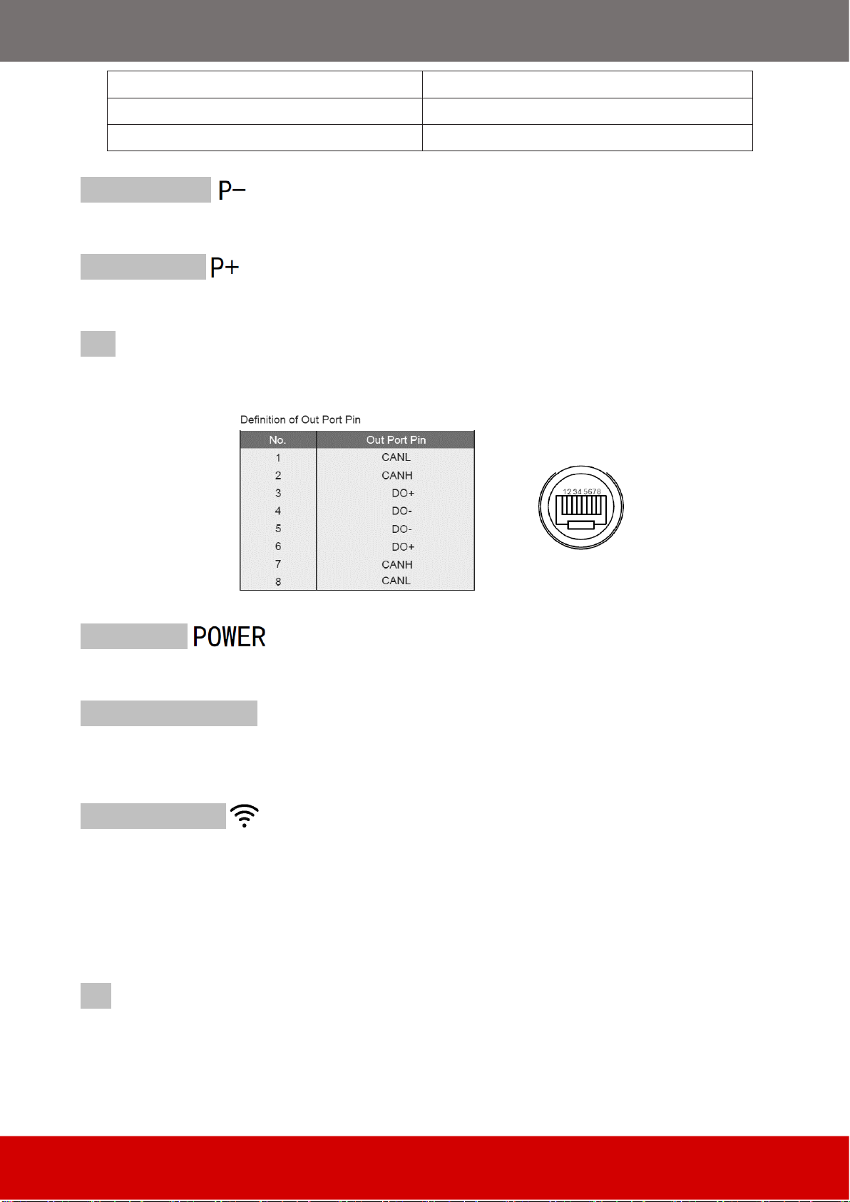
~ 4 ~
3. Parallel communication port OUT
8. Parallel communication port IN
4. Power switch
9. Upper and lower fixing plate position
5. System state indicator
Battery negative
The battery system charge and discharge negative port.
Battery positive
The battery system charge and discharge positive port.
OUT port
Parallel Communication Terminal: (RJ45 port) Connect “IN” Terminal of next battery for
communication between multiple parallel batteries.
Power Switch
Power Switch: to turn ON/OFF the BMS of the entire battery system.
System state indicator
Indicates the operating status of the entire battery system, include SOC, RUN, ALARM, and
ERROR. Refer to introduction in 2.2.2.
Wi-Fi module port
The data acquisition stick (Wi-Fi) mainly collects and records the working state of the bat-
tery system for long-term and effective monitoring of the battery system, and receives vari-
ous information of the system from the battery end. The data is sent wirelessly to the moni-
toring platform, and the real-time status and historical data of the battery system can be
presented in the form of graphs, which is intuitive, clear, and easy to understand.
PCS port
Inverter communication terminal: (RJ45 port) follow the CAN protocol (baud rate: 500K),
used to output battery information to the inverter.

~ 5 ~
IN port
Parallel Communication Terminal: (RJ45 port) Connect “out” Terminal of Previous battery
for communication between multiple parallel batteries.
Upper and lower fixing plate position
Use the fixing plate to secure the upper and lower layers together to prevent tilting and col-
lapse, with two fixing plates on the left and right between each two layers.
BMS function:
Protection and Alarm
Management and Monitor
Charge/Discharge End
Intelligent Protect Mode
Charge Over Voltage
Intelligent Charge Mode
Discharge Under Voltage
Protect, Charge Current Limit
Charge/Discharge Over Current
Intelligent Protect Mode
High/Low Temperature(cell/BMS)
Intelligent Protect Mode
Short Circuit
Protect
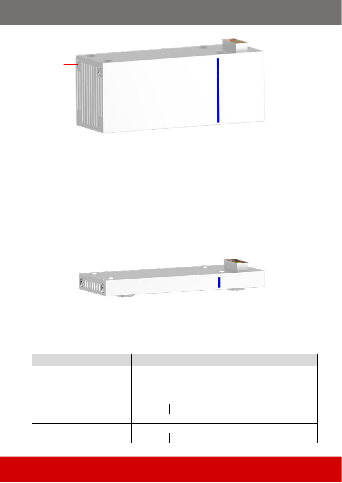
2.2.2 AI-W5.1-PDU1 Interface
1. Wall fixing plate position
2. System earthing position

~ 6 ~
Wall fixing plate position
After installation, for the battery system fixed on the wall to prevent tilt.
System earthing position
Protective earthing for the battery system connecting to the PE.
LED Status Indicator Instructions:
RUN LED
: green, keep flashing when power switch is on.
ALARM LED
: yellow, flashes when battery has alarm.
ERROR LED
: red, long bright if battery is protected.
SOC LED
: 5 blue LEDs, battery capacity indicator, each light represents 20% capacity.
Condition
RUN
ALARM
Error
LED1
LED 2
LED 3
LED 4
LED 5
Power off
off
Charge
Blink
Blink if Alarm
Exists
off
Show SOC & highest LED
blink
Discharge or Idle
off
Show SOC & long bright
Alarm
Blink
off
Other LEDs are same as
above
System error/Protect
off
long bright
Upgrade
Blink Fastly
Critical Error
Blink Slowly
2.2.3 AI-W5.1 Module Interface
~ 7 ~
1. Movable handle handling position,
Upper and lower fixing plate position
4. ALARM LED
2. Battery module dock terminals
5. ERROR LED
3. RUN LED
RUN LED:
green, keep flashing when the power switch is on.
ALARM LED:
yellow, flashes when battery has alarm.
ERROR LED:
red, long bright if battery is protected.
2.2.4 AI-W5.1-Base Interface
1. Upper and lower fixing plate position
2. Battery module dock terminals
2.3
System Technical Data
Main Parameter
AI-W5.1
Battery Chemistry
LiFePO4
Battery Module Energy (kWh)
5.12
Battery Module Voltage (V)
51.2
Battery Module Capacity (Ah)
100
Battery Module Quantity
2
3
4
5
6
Nominal Voltage (V)
51.2
Operating Voltage(V)
43.2~57.6
Energy (kWh)
10.24
15.36
20.48
25.6
30.72

~ 8 ~
Usable Energy (kWh) [1]
9.2
13.8
18.4
23.0
27.6
Charge/Discharge
Current (A)
Recommend [2]
100
150
200
200
200
Max. [2]
180
210
240
250
250
Peak(10s,25℃)
270
315
360
360
360
Other Parameter
Recommend Depth of Discharge
90%
System Dimension (W/D/H, mm)
720*255*770
720*255*1055
720*255*1340
720*255*1625
720*255*1910
System Weight (kg)
124
177
230
283
336
Master LED Indicator
5LED(SOC:20%~100%), 3LED (working, alarming, protecting)
IP Rating of Enclosure
IP65
Operating Temperature
Charge: 0~55℃/ Discharge: -20℃~55℃
Storage Temperature
-20℃~35℃
Humidity
5%~95%
Altitude
≤2000m
Installation
Floor-Mounted
Communication Port
CAN2.0, RS485
Certification
IEC62619, CE, VDE2510-10, CEI 0-21, UN38.3
Battery PDU1
720*255*110(W/D/H, mm), 10kg
Battery Module
720*255*285(W/D/H, mm), 53kg
Battery Base
720*255*85(W/D/H, mm), 8kg
[1] DC Usable Energy, test conditions: 90% DOD, 0.5C charge & discharge at 25°C. System usable energy may vary due to sys-
tem configuration parameters.
[2] The current is affected by temperature and SOC.
2.4
Battery Module Data (AI-W5.1)
Main Parameter
AI-W5.1
Battery Chemistry
LiFePO4
Battery Module Energy (kWh)
5.12
Battery Module Voltage (V)
51.2
Battery Module Capacity (Ah)
100
Battery Module Serial Cell QTY.
16
Nominal Voltage (V)
51.2
Operating Voltage(V)
43.2~57.6
Charge/Discharge Current (A)
Recommend [1]
50
Max. [1]
100
Peak(10s,25℃)
150
Other Parameter
Recommend Depth of Discharge
90%
Battery Module Dimension (W/D/H, mm)
720*255*285
Battery Module Weight (kg)
53
Master LED Indicator
3LED (working, alarming, protecting)
IP Rating of Enclosure
IP65

~ 9 ~
Operating Temperature
Charge: 0~55℃/ Discharge: -20℃~55℃
Storage Temperature
-20℃~35℃
Humidity
5%~95%
Altitude
≤2000m
Cycle Life
≥6000(25℃±2 ℃,0.5C/0.5C,70%EOL)
Installation
Floor-Mounted
Communication Port
CAN2.0, RS485
Energy Throughput
16MWh(@70%EOL)
Certification
IEC62619, CE, VDE2510-10, CEI 0-21, UN38.3
[1] The current is affected by temperature and SOC.
2.5
Product application solutions
The following illustration shows basic application of this battery.
It also includes following devices to have a complete running system.
- Generator or Utility
- PV modules
- Low voltage Hybrid Inverters (Charge & Discharge)
Consult with your system integrator for other possible system architectures depending
on your requirements.
The picture is only an effect picture, please refer to the actual product, the final interpre-
tation right belongs to DEYE.
3
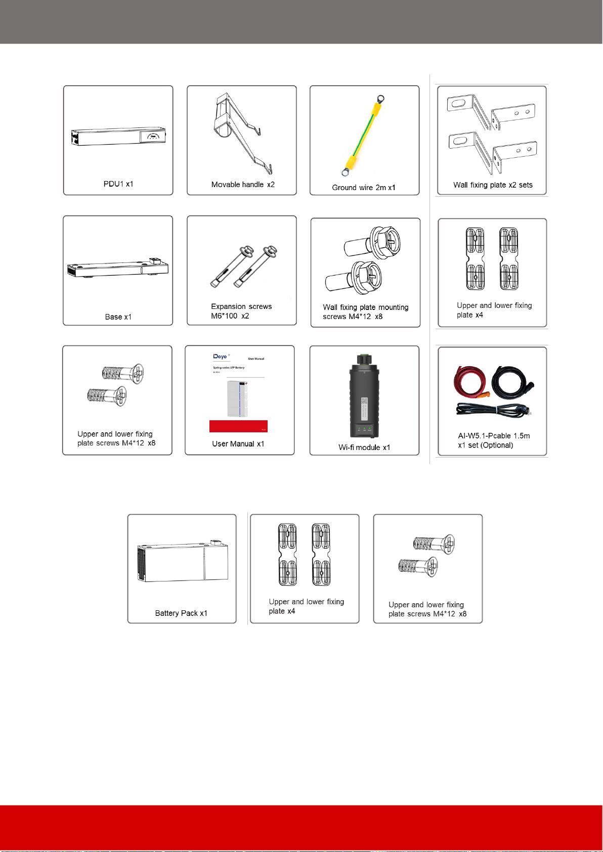
Parts List
Check the equipment before installation. Please make sure nothing is damaged in the pack-
age. You should have received the items in the following package.
~ 10 ~
3.1
System Power Distribute Unit packaging box Parts List
3.2
Li-ion Battery Pack packaging box Parts List
4
Preparations for Installation
4.1
Explanation of Symbol

~ 11 ~
4.2
Tools
These tools are required to install the battery.

~ 12 ~
NOTE:
Use properly insulated tools to prevent accident tale electric shock or short circuits.
If insulated tools are not available, cover the entire exposed metal surfaces of the available
tools, except their tips, with electrical tape.
4.3
Safety Gear
It is recommended to wear the following safety gear when dealing with the battery pack.
5
Installation instructions
5.1
Installation Precaution
Lithium battery is designed for outdoor use (IP65). But please avoid direct sunlight, rain ex-
posure, snow laying up during installation and operation.
Make sure that the installation location meets the following conditions:
The installation area shall avoid of direct sunlight.
The floor and walls are completely water proof.
The wall is flat and level.
There are no flammable or explosive materials.
The ambient temperature is within the range from -20°C to 50°C. Not in the cool air directly.
There is minimal dust and dirt in the area.
The distance from heat source is more than 2 meters.
The distance from air outlet of inverter is more than 0.5 meters.
Do not place at a children or pet touchable area.
There are no mandatory ventilation requirements for battery module, but please avoid of in-
stallation in confined area. Do not cover or wrap the battery case or cabinet.
The aeration shall avoid of high salinity, humidity, or temperature. Not in environment of
precipitation or humidity (>95%).
Not higher than altitude of about 2000 meters above sea level.
CAUTION
Cleaning. Before installing and powering up the system, dust and iron filings must be removed
to keep the environment clean. The system cannot be installed in desert areas without a shell to
protect against sand.

~ 13 ~
CAUTION
Temperature. If the ambient temperature is outside the operating range, the battery pack stops
operating to protect itself. The optimal temperature range for the battery pack to operate is 15°C
to 35°C.
Frequent exposure to harsh temperatures may deteriorate the performance and life of the bat-
tery pack.
CAUTION
Fire extinguisher system. For safety, it is best to have a fire extinguisher system. The fire protec-
tion system needs to be checked regularly to keep it in normal condition. For use and mainte-
nance requirements, follow local fire equipment guidelines.
CAUTION
Grounding system. Before the battery is installed, it must be determined that the basement
grounding point is stable and reliable. If the battery system is installed in a separate equipment
compartment (such as a container), the grounding of the cabin must be stable and reliable.
The resistance of the grounding system is not less than 0.1Ω
CAUTION
Handling and placement. The weight of the single battery module is 53kg. If there is no han-
dling tool, at least 2 persons must carry it.
The battery module must be installed by at least two persons using movable handles.
The PDU and Base are light to handle and place and can be installed by a single person.
5.2
Install the Battery
CAUTION
Remember that this battery is heavy! Please be careful when lilting out from the package.
The battery module must be installed by at least two persons using movable handles.
5.2.1 Selection of installation sites
It is necessary to choose the appropriate installation site according to the requirements of 5.1.
The system must not be immersed in water. The battery base should not be placed in rain or
other water sources. It is recommended that the height of the base is 300mm from the ground,
and the weight of the base should be able to support the weight of the entire battery system
124kg~336kg.
The installation location is recommended to meet the size requirements of the figure below:

~ 14 ~
5.2.2 Unpacking order
First open the box of the System Power Distribute Unit packaging box, take out the base and
handle, the handle is used to carry the battery module, without the handle the battery module
will be difficult to remove from the battery box.
5.2.3 Installation order
i.
Put the installed base and feet along the wall, and keep the distance of 10~35 mm be-
tween the wall and the base.
ii.
Open the battery box, take a battery module from the package out. Put one battery mod-
ule on the base. Pay attention to the direction of the module to make sure that the blind-
mating connectors of the module and the base are at the same side.
~ 15 ~
iii.
Repeat the operations for other battery modules.
iv.
Install the wall fixing plate (PDU part) to the PDU. To do this, follow the instructions below
to install and tighten them on the back side of PDU (torque: 2 Nm).
v.
Put the PDU on top of the battery modules.

~ 16 ~
vi.
Fix the upper and lower fixing plate connection between the battery module and the base,
between battery modules, and between PDU and battery module. To do this, insert the
screws (M4x12) through the holes on them, using a Hexagon Wrench (2.5mm) and tighten
them (torque: 2 Nm).
vii.
Hold the wall fixing plate (wall part) where it intends to be mounted on the wall and mark
the position of the drill holes. Please pay attention that there may be power cables or other
supply lines (e.g., gas or water) routed inside of the wall. Ensure that no lines are laid in the
wall, which could be damaged when drilling holes.
viii.
Set the wall fixing plate (wall part) aside and drill the marked holes. Choose the recom-
mend drill head (10mm) to drill 2 holes on the wall,100mm-110mm deep. Put the wall fixing
plate (wall part) in front of the holes, then insert the expansion screw of M6*100 and tighten.
ix.
Fix the two hangers (wall part and PDU part) with M4X12 screws, using a cylinder screw-
driver (10 mm) to tighten it (torque: 2 Nm).
~ 17 ~
5.3
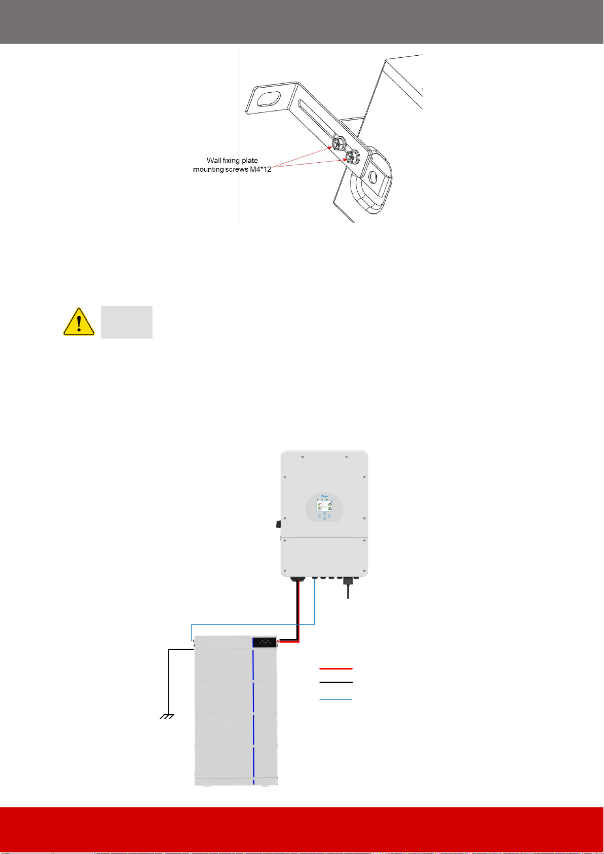
Electrical Connection
5.3.1
Single
Battery System (It is suitable for scenarios where the inverter power ≤
12kW)
CAUTION
It should be noted that the maximum current of single battery system is 250A (inverter
power must not exceed 12kW), exceeding 250A will cause heating of the connectors and
cable, and in severe cases, it will cause a fire accident.
If the inverter power exceeds 12kW, the
connection
mode must be used
Multiple Battery
System
!
Schematic diagram of connection of single battery system:
Battery
Input
AI-W5.1-PCable
(2/0AWG or 70mm2)
Max.250A
PCS port
Hybrid
Inverter
RJ45 CAN communication line
Positive Power line
Negative Power line
~ 18 ~
5.3.2
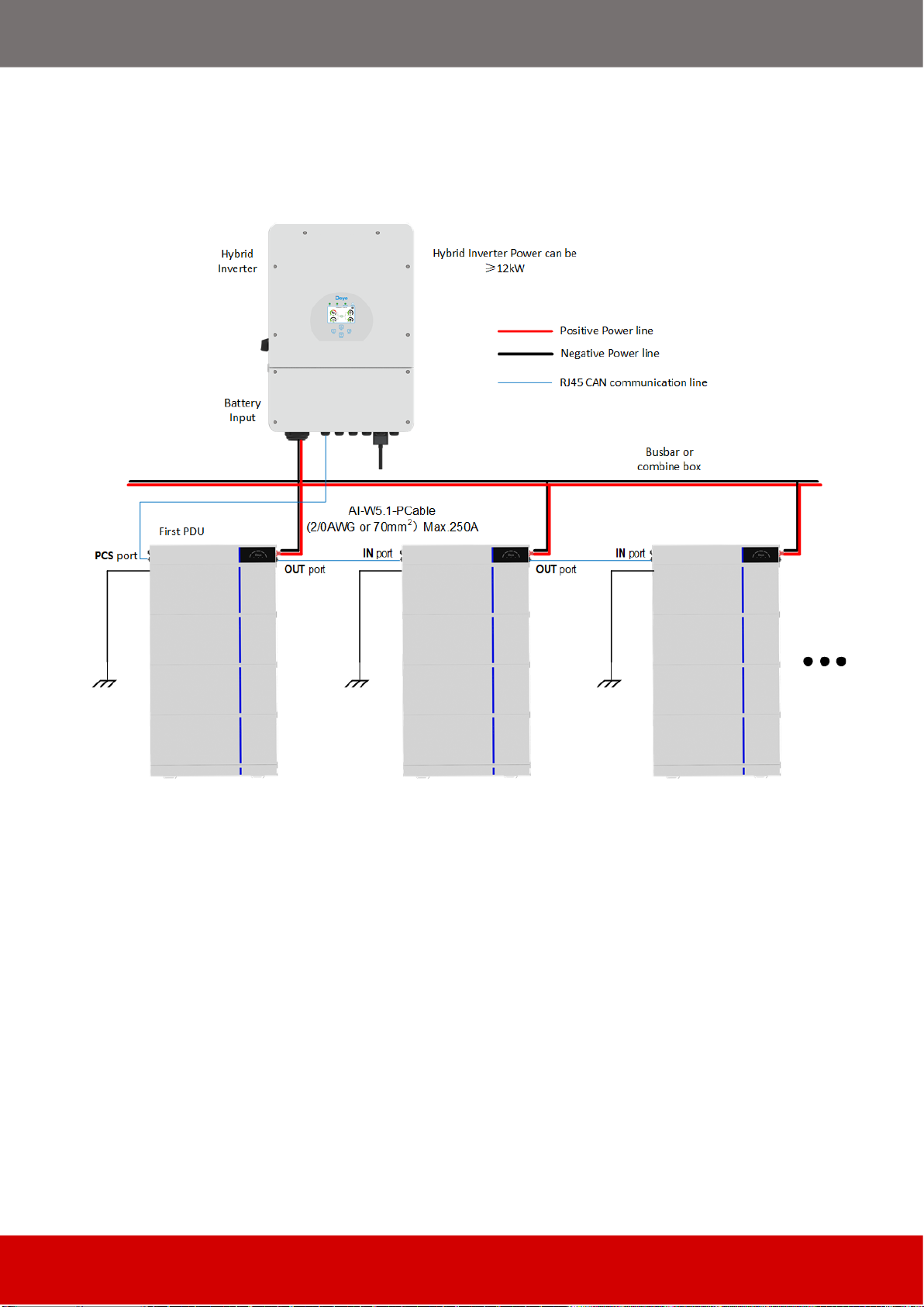
Multiple Battery System
(It is suitable for scenarios where the inverter power ≥
12kW)
Schematic diagram of connection of Multiple batteries system:
or
larger capacity systems:
Other manuals for Spring Series
2
This manual suits for next models
1
Table of contents
Other Deye Camera Accessories manuals


