DFE Ultralights Ascender III-C 2001 Owner's manual
1
D
DF
FE
E
U
Ul
lt
tr
ra
al
li
ig
gh
ht
ts
s
A
As
sc
ce
en
nd
de
er
r
I
II
II
I-
-C
C
P
Pi
il
lo
ot
t’
’s
s
O
Op
pe
er
ra
at
ti
in
ng
g
H
Ha
an
nd
db
bo
oo
ok
k
Applicable to:
Serial Number: ARZ01
Registration: C-IZZZ
Version 1.27 – August 2004
Pilot’s Operating Handbook DFE Ultralights Ascender III-C

2
Pilot’s Operating Handbook DFE Ultralights Ascender III-C
N T
FOREWORD
This handbook describes the features and systems of the DFE Ultralights Ascender III-C
ultralight airplane. Operational procedures and performance data are provided so that the aircraft
can be operated as safely as possible.
It is strongly recommended that the pilot be familiar with the aircraft and this handbook prior to
flight.
This handbook applies specifically to 2001 model DFE Ascender III-C, Serial Number ARZ01,
registered C-IZZZ equipped with a Rotax 503 DCDI engine.
All placards and operating limitations MUST be adhered to.
INTERPRETATION
The words “WARNING”, “CAUTION”, and “NOTE” are used throughout the handbook with
the following definitions:
W
W
WA
A
AR
R
RN
N
NI
I
IN
N
NG
G
G
An operating procedure, practice or condition which may result in
injury or fatality if not carefully observed or followed.
C
C
CA
A
AU
U
UT
T
TI
I
IO
O
ON
N
N
An operating procedure, practice or condition which,
if not strictly observed, may damage the aircraft or equipment.
N
NO
O
OT
TE
E
E
An operating procedure, practice or condition
which it is essential to emphasize.

3
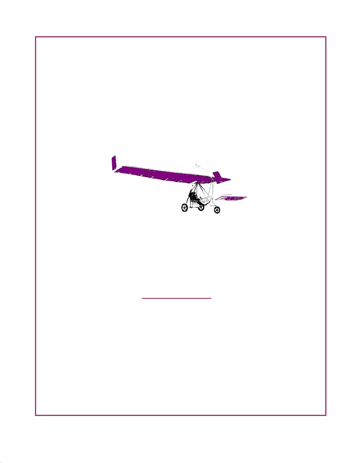
DFE Ascender III-C
General Arrangement Photos
Pilot’s Operating Handbook DFE Ultralights Ascender III-C

4
Pilot’s Operating Handbook DFE Ultralights Ascender III-C
TABLE OF CONTENTS
SECTION I OPERATING LIMITATIONS
GENERAL
FLIGHT OPERATIONS
POWERPLANT LIMITATIONS
AIRSPEED LIMITATIONS
WEIGHT AND BALANCE LIMITS
FLIGHT LOAD FACTORS
MANEUVERS
REQUIRED PLACARDS
SECTION II EMERGENCY PROCEDURES
GENERAL
FIRE
ENGINE FIRE DURING START
ENGINE FIRE IN FLIGHT
ENGINE MALFUNCTION
ENGINE FAILURE ON TAKEOFF
ENGINE AIR RESTART
PARTIAL POWER LOSS/ROUGH RUNNING
LANDING EMERGENCIES
PRECAUTIONARY LANDING APPROACH
FORCED LANDING (COMPLETE POWER FAILURE)
DITCHING
UNUSUAL FLIGHT CONDITIONS
SEVERE TURBULENCE
STALLS
SPINS
STRUCTURAL FAILURE OR MID-AIR COLLISION
SECTION III NORMAL OPERATING PROCEDURES
GENERAL
PREFLIGHT BRIEFING
LIST OF WINGNUTS AND SAFETY RINGS
PREFLIGHT INSPECTION
BEFORE STARTING
STARTING
TAXI
BEFORE TAKEOFF
TAKEOFF-NORMAL

5
Pilot’s Operating Handbook DFE Ultralights Ascender III-C
TAKEOFF-OBSTACLE
TAKEOFF-SOFT FIELD
CLIMB
CRUISE
DESCENT
LANDING-NORMAL
LANDING-OBSTACLE
SHUTDOWN
SECTION IV FLIGHT PERFORMANCE
GENERAL
AIRSPEED CORRECTION
STALL SPEEDS
TAKEOFF PERFORMANCE
CLIMB PERFORMANCE
CRUISE PERFORMANCE
LANDING PERFORMANCE
SECTION V WEIGHT AND BALANCE
GENERAL
FLIGHT ENVELOPE
LOADING PROCEDURES
SAMPLE LOADING PROBLEM
LOADING GRAPH
SECTION VI AIRCRAFT & SYSTEMS DESCRIPTION
GENERAL
AIRCRAFT FILE
AIRFRAME STRUCTURE
MODIFICATIONS
ENGINE
FLIGHT CONTROLS
LANDING GEAR
ELECTRICAL SYSTEM
FUEL SYSTEM
HEATING AND VENTILATION
FLIGHT INSTRUMENTS
AVIONICS
CABIN FEATURES
Table of contents


