DFE RFA User manual

INSTRUCTION MANUAL
Ribbon-Filament Transducer
Model RFA
DOC 801-0784 R4

Dover Flexo Electronics
307 Pickering Road
Rochester, NH 03867- 4630
U.S.A.
FOR ASSISTANCE:
TECHNICAL SERVICE - Installations, Start-Up, Troubleshooting, Repairs, Field Service
or Returns. Call (603) 332-6150 and ask for Technical
CUSTOMER SERVICE - Replacement Parts, Individual Products, Questions about
Orders, Manuals. Call (603) 332-6150 and ask for Customer
SALES - Product Information, System Application Questions or Placing
Orders, Please e-mail us at: [email protected] or call
(603) 332-6150 and ask for Sales.
Telephone: (603) 332-6150 Fax: (603) 332-3758
E-mail: [email protected] Internet: www.dfe.com
©2022 Dover Flexo Electronics, Inc. All rights reserved. Dover Flexo Electronics has made reasonable effort to ensure accuracy of
this document. However, NO WARRANTY, whether expressed or implied, is given regarding the completeness or correctness of
information in this document. Dover Flexo Electronics shall not be liable for damages of any kind arising from the use or misuse of
this document. Dover Flexo Electronics reserves the right to make changes, additions, and deletions to this document without notice
and without obligation.

This label indicates: “Read The Manual”
Make sure you read and understand all instructions and safety precautions listed in this manual
before installing or operating your Model RFA Tension Transducer. If you have any questions
concerning the operation of your device or the information in this manual, please contact us.
Email: [email protected]
Telephone: (603) 332-6150
•Observe all warning labels.
•Never remove warning labels.
WARNING: During installation care should be taken not to drop the Model RFA
transducer, handle the unit with care, sudden jolts or drops can damage its components
and serious injury could result.
WARNING: If this equipment is not connected or operated in the manner specified, the
operating safety of this unit or of connected equipment cannot be guaranteed.
WARNING: Do not connect a standard excitation (5V) tension transducer to a DFE
amplifier with the Extended Range (XRE) option enabled (10V), the transducer may be
damaged.

Table of Contents
DOCUMENT CONVENTIONS ................................................................................................... 5
1GENERAL DESCRIPTION ................................................................................................. 6
1.1 CONSTRUCTION AND MECHANICAL OPERATION (see Figure 1)........................... 6
1.2 SPECIFICATIONS....................................................................................................... 7
1.3 STANDARD FEATURES ............................................................................................. 7
1.4 CONFIGURATION CHOICES...................................................................................... 7
1.5 OPTIONS .................................................................................................................... 8
2INSTALLATION.................................................................................................................. 9
2.1 DIMENSIONS .............................................................................................................. 9
2.2 PRE-INSTALLATION REQUIREMENTS ....................................................................10
2.3 INSTALLATION ..........................................................................................................11
2.4 ELECTRICAL OPERATION........................................................................................12
3CALIBRATION AND SETUP.............................................................................................13
3.1 INTRODUCTION ........................................................................................................13
3.2 ZERO THE TENSION METER....................................................................................13
3.3 CALIBRATE THE TENSION METER..........................................................................13
4CARE AND MAINTENANCE.............................................................................................14
4.1 BEARING LIFE ...........................................................................................................14
4.2 DISASSEMBLY AND REASSEMBLY - TOOLS REQUIRED ......................................14
4.3 CHANGING THE BEARING(S) AND/OR WHEEL.......................................................14
5TROUBLESHOOTING.......................................................................................................15
APPENDIX A: SELECTION OF LOAD RATING ......................................................................17
APPENDIX B: TYPICAL TENSIONS FOR VARIOUS MATERIALS.........................................19
TERMS AND CONDITIONS OF SALE AND SHIPMENT .........................................................20

5
DOCUMENT CONVENTIONS
NOTES - Highlight important concepts, decisions you must make, or the implications of those
decisions.
CAUTIONS - Tell you when equipment may be damaged if the procedure is not followed
properly.
WARNINGS - Tell you when people may be injured, or equipment may be damaged if the
procedure is not followed properly.
Numbered lists indicate tasks that should be carried out in sequence:
1. First do this
2. Then do this

6
1 GENERAL DESCRIPTION
The Model RFA “Ribbon-Filament” Tension Transducer is an electro-mechanical device that converts ribbon,
web, or filament tension into a DC voltage proportional to tension. The voltage is amplified in external electronic
circuitry such as a DFE Tension Amplifier, Indicator or Closed-Loop Controller which is calibrated to output and/or
display actual tension. The tension reading is expressed in pounds, ounces, grams, kilograms, newtons, or any
other desirable units. It can also be supplied to a regulator circuit to control tension automatically.
The RFA Tension Transducer is typically used in applications where the machine has only one side frame and
the idler wheels are cantilevered. The information in this section will help give a clear understanding of the RFA
Tension Transducer system - how it works and how it’s used.
1.1 CONSTRUCTION AND MECHANICAL OPERATION (SEE FIGURE 1)
The standard RFA Transducer wheels are manufactured of aluminum to be lightweight and of low inertia,
and the ribbon wheels and filament wheels are given a hard coat anodized surface finish to be durable.
The bearings are standard deep-groove ball type with shields to discourage entry of contaminants.
Custom wheel geometries and/or finishes are available including those made by the customer to be
mounted on the adapter wheel, subject to specific DFE engineering approval.
Inside the transducer is a single beam having two parallel cantilevered webs with strain gages mounted
on each. When tension is applied, the beam deflects a small amount, causing an electrical output from
the strain gages which is directly proportional to the filament tension.
The bore of the housing acts as a mechanical stop, preventing damage to the beam and gages from
accidental overloads. The stop is functional through 360 degrees, so the overload condition may occur
from any direction, not just the load direction. In all cases, the beam is prevented from deflecting far
enough to cause any damage.
Figure 1 - CUT-AWAY VIEW OF RFA TRANSDUCER

7
1.2 SPECIFICATIONS
ELECTRICAL SPECIFICATIONS
Excitation Voltage: 5 VDC max (Std), 10 VDC max (XR Option)
Output: 100 mV/V, nominal
Strain Gages: Semiconductor, 100 ohms nominal resistance
Repeatability: +/- 1/4% FS
Linearity and Hysteresis Combined: +/- 1/2% FS
Temperature Range: -10° F to +200° F (-23° C to +93° C)
Temperature Coefficient: 0.02% per degree F, typical (0.01% per degree C, typical)
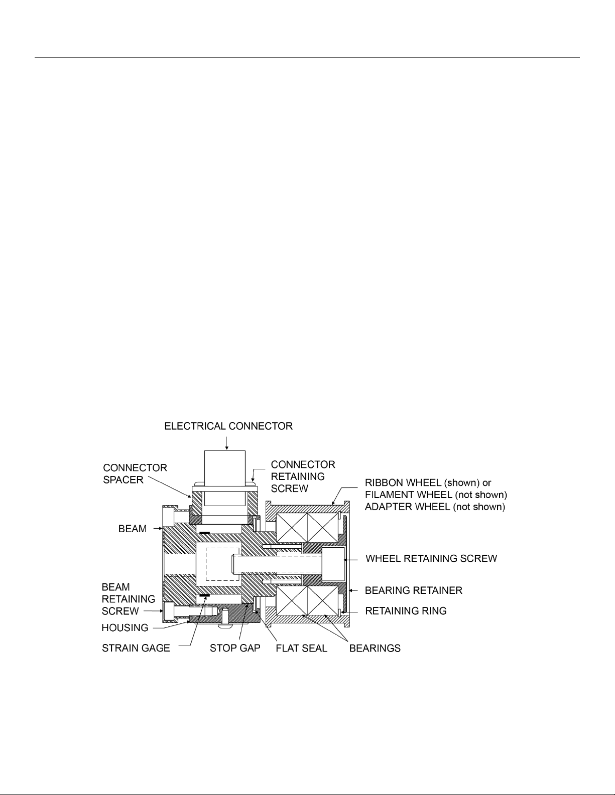
Electrical Connector: MIL Spec - PT02E10-6P
Electrical Connections:
Pin A (White): Signal Output (-)
Pin B (Black): Excitation (+)
Pin C (Red):Excitation (-)
Pin D (Green):Signal Output (+)
Pin E (Blue): Excitation (-)
Pin F (Brown): Excitation (+)
Mating Electrical Connector:
MIL Spec (Standard) - 6 socket, female, PT06E10-6S
MECHANICAL SPECIFICATIONS
Materials: 303 stainless steel and 7075-T6 aluminum, black anodized hard coat wheel finish.
Maximum Overload Capacity: Four times the load rating.
Deflection: .005" typical (0.127 mm typical)
Standard Connector Position:
S, FL styles - 6 o'clock
PB style - Rear with reference to force direction
Load Ratings: 10, 25, 50, 100, 150 (45, 111, 222, 445, 670 N)
Note: The information below is only applicable if a DFE Wheel or shaft assembly is used.
Break-Away Torque: 0.25 in-oz (18 gram-cm) typical
Basic Dynamic Load Rating of Bearings: 4300 lbs (19120 N)
Wheel Weights:
Filament 0.49 lbs (222 g)
Ribbon 0.45 lbs (204 g)
Adapter 0.65 lbs (295 g)
1.3 STANDARD FEATURES
Dual Cantilever Beam: Provides high strength and accuracy at low tension.
Stainless Steel and Aluminum Construction: Excellent durability and corrosion resistance.
Compact Size: For easy mounting--even in small spaces.
1.4 CONFIGURATION CHOICES
These are explanations of standard choices of various configurations that were specified for your
application.
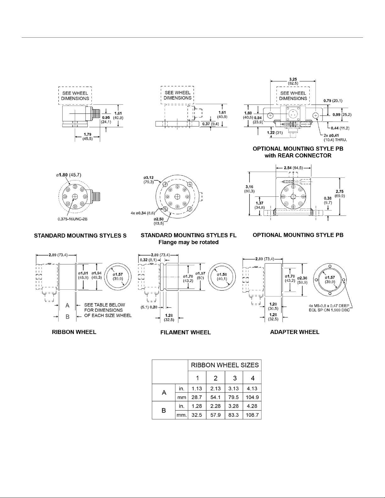
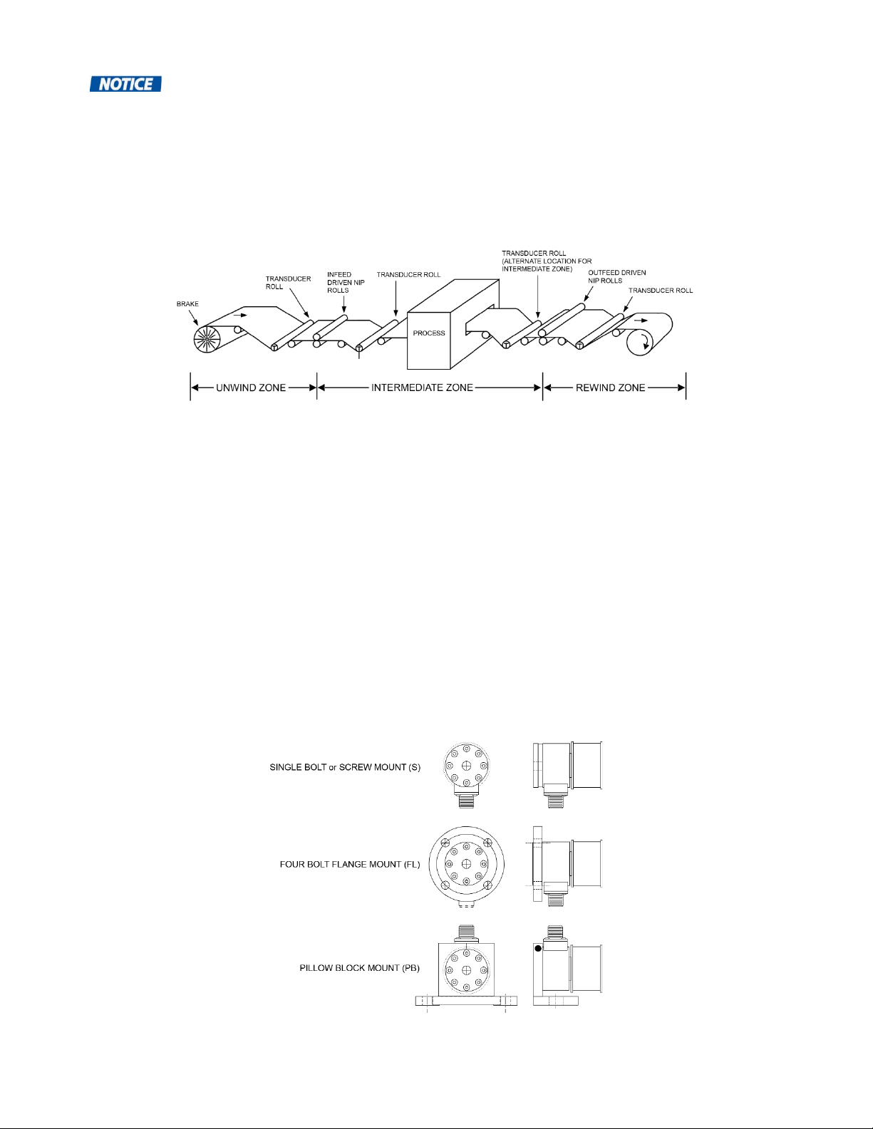
Mounting Styles: Screw or Bolt mount (S) uses a single bolt to mount to machine frame. Pillow Block
bracket (PB) uses a right-angle bracket to mount onto the machine frame. Flange mount (FL) uses a

8
four-bolt flange mounted onto the machine frame which can be rotated to any position for precise
orientation.
Load Ratings:10, 25, 50, 100, 150 lbs (45, 111, 222, 445, 670 N)
DFE Wheel Types: Ribbon Wheel (specify width of 1 to 4 inches), Filament Wheel, Adapter Wheel (hub
for custom applications).
Connector Positions:
S, FL: 1:30, 3:00, 4:30, 6:00 (std.), 7:30, 9:00, 10:30, 12:00.
PB: Rear (std.), 1:30, 3:00, 9:00, 10:30, 12:00 with reference to force direction.
1.5 OPTIONS
Extended Range (XR): Accepts 10V excitation from a supported amplifier, indicator, or controller with
(XRE) option.
Metric Mounting Screw (MMS): Metric mounting thread for S type transducers.

9
2 INSTALLATION
2.1 DIMENSIONS
Figure 2 – DIMENSIONS

10
2.2 PRE-INSTALLATION REQUIREMENTS
Note: No brakes, clutches, belts, chains, or gears should be attached to the transducer
wheel. It cannot be a nip roll or be in contact with a nip wheel. Nothing must contact the wheel except
the ribbon or filament.
1. TENSION ZONE
The transducer must be located in the tension zone which is to be monitored or controlled. The
beginning or end of any tension zone is always at a nip (driven or braked), unwind shaft, rewind
shaft, or drag bar. Any element in the filament path that can change tension is at one end of a tension
zone.
Figure 3- TENSION ZONES
2. WRAP ANGLE
The web or filament must always contact the transducer wheel in the same way. The wrap angle
must not change as the unwind or rewind reel diameter changes. Therefore, there must be at least
one idler wheel between the transducer and the unwind or rewind shaft. If the machine has more
than one web path, be sure to choose a location that is wrapped the same for each. Otherwise, it will
be necessary to install an additional idler roll or transducer, or dual calibration circuitry, or all three. If
the wrap angle is allowed to change, the transducer output will change with angle as well as tension,
and accuracy will be reduced.
3. MOUNTING SURFACE
The structure on which the transducers are mounted must be very stable and strong. Any
movement of the structure may be sensed by the transducers and may cause inaccurate tension
readings. The surfaces must also be smooth and flat so the transducers can be properly aligned
during installation. The RFA Transducer is sold in three different mounting styles and attached to the
machine frame by one of three methods: A single bolt (S) through the back of the unit, a four-bolt
flange (FL), or a pillow-block type bracket (PB).
Figure 4 – RFA MOUNTING STYLES

11
2.3 INSTALLATION
Model RFA Tension Transducers are very easy to install. Follow the simple steps below.
1. ORIENT THE TRANSDUCER (see Figure 5)
The transducer must be turned so the Tension Force arrow (or the notch on the rear edge of the
beam) points in the same direction as the Tension Force.
Figure 5 - TENSION FORCE DIRECTION
If you are installing an "S" or "FL",” style transducer, adjust the transducer on the machine frame by
hand (do not use a wrench) so the arrow (or notch) will bisect the wrap angle.
If you are installing a "PB" bracket style transducer, the transducer is already assembled with the
force direction orientation specified when purchased. It can be aligned more accurately by loosening
the clamp bolt on top of the bracket and turning the transducer by hand (pry the top of the bracket
open with a screwdriver if necessary). Re-tighten the clamp bolt.
2. INSTALL AND TIGHTEN MOUNTING FASTENERS
With the transducer properly oriented with respect to its tension force, install mounting fasteners and
tighten to secure the transducer in place.
WARNING: During installation care should be taken not to drop the RFA Transducer, handle the unit
with care, sudden jolts or drops can damage its components and serious injury could result.
3. CONNECT TRANSDUCER TO ELECTRONICS
Make your connections to your electronics by plugging in the cables, being careful to align the
connectors properly - never force them together. Tighten the connectors to properly seat the pins.
CAUTION: If a non-standard DFE wheel or shaft assembly is used, make certain that it does not
bottom-out on the transducer, as this will interfere with the proper function of the transducer and
possibly cause damage to the unit.

12
2.4 ELECTRICAL OPERATION
The Model RFA Transducer is used singularly. Web tension exerts a force on the roll/wheel which is
transmitted to the cantilever beam. Four semiconductor strain gages are mounted on the beam, two on
the top and two on the bottom. As force is applied and the beam deflects, the top gages are stretched,
and the bottom gages are compressed. This increases the electrical resistance of the top gages and
decreases the resistance of the bottom gages. The gages are electrically connected in a Wheatstone
bridge configuration. The output from the bridge is the sum of the output from sets of gages.
Figure 6 - MODEL RFA TRANSDUCER WIRING
The physical location of the strain gages, on opposite sides of the beam, ensures that each gage
experiences the same temperature variations. This, and the Wheatstone bridge configuration, provides
automatic temperature compensation and a stable output.
The strain gages used in the RFA transducer are high output semiconductor devices with up to 33 times
greater output than the less expensive foil gages used in some budget transducers. Therefore, the signal
amplifier used with these RFA transducers is a very stable, low-gain design. An added benefit of the high
output is inherent immunity to electrical noise.

13
3 CALIBRATION AND SETUP
3.1 INTRODUCTION
No physical calibration adjustments are required with the RFA Transducer. Follow the electronic
calibration steps listed in the manual of the Tension Controller, Indicator or Amplifier being used with the
device. Some general calibration instructions are listed below for reference.
3.2 ZERO THE TENSION METER
1. With no weight on the idler roll and power connected to the devices, press the Quik-Cal™ Zero
button on the supported amplifier or indicator. If using a touchscreen indicator or controller, press the
Zero command at the touchscreen menu prompt.
3.3 CALIBRATE THE TENSION METER
1. See Figure 7. Pass the rope over the Transducer wheel / pulley in the same path as the web follows.
Tie the end in the machine at least one idler roll beyond the Transducer. Pass the other end by at
least one idler roll before the Transducer. Be sure the rope does not pass over any driven rolls,
braked rolls, or dead bars (this will cause in-accurate calibration). Attach the weight to the free end of
the rope and let it hang without touching anything.
2. Wait for the weight to stop swinging.
3. Press the Calibrate button on supported Quik-Cal™ amplifiers and indicators or press the Calibrate
command at the touchscreen menu prompt.
4. This concludes the calibration procedure.
Figure 7 – WEB PATH

14
4 CARE AND MAINTENANCE
Your Dover Flexo RFA Tension Transducer has been manufactured of quality materials. With proper
application and installation your transducer should be relatively maintenance free and long lasting. Any
changes in your application which affect the dynamics of your equipment such as web speed, net force,
material, etc. could possibly require upgrading of load rating or wheel change. Contact Dover for specific
information and engineering assistance.
4.1 BEARING LIFE
The bearings in the RFA Transducer will turn continuously in normal operation. They have been selected
to give a long service life under typical operating conditions if properly maintained with lubrication. Use
the formula below to find the L10 life, in hours, for your application.
To find the radial load (P) for your application, use the appropriate sizing formula in Appendix A,
substituting 2 for the 4 to eliminate the oversizing factor.
RPM = 3.82 x line speed in feet per minute/diameter of transducer wheel in inches
(RPM = 318.3 x line speed in meters per minute/diameter of transducer wheel in millimeters)
BEARING SPECIFICATIONS
Bearing Type
Rated Load (C)
Maximum Speed (RPM)
Ball
4,300 lbs (19,120 N)
20,000
LIFE CALCULATION FORMULAS (where Pis radial load as described above)
L10 = (16667 / RPM) x (C) / P)3, for ball bearings
An L10 life of 20,000 to 30,000 hours is usually considered satisfactory for web process machinery such
as printing presses, coaters, etc.
4.2 DISASSEMBLY AND REASSEMBLY -TOOLS REQUIRED
1. Right-angle Allen wrenches.
2. A small flat blade screwdriver.
4.3 CHANGING THE BEARING(S) AND/OR WHEEL
1. Remove the single M8 cap screw holding the wheel, bearings, retainer, and spacer (if any) onto the
beam.
2. Remove the wheel, bearings, and bearing retainer from the beam. If the hardware does not separate
easily, it may be carefully pried apart by putting flat blade screwdrivers between the wheel and
housing and prying equally on opposite sides of the assembly so as not to distort the beam.
3. Remove the bearing retainer, retaining ring and bearings from the wheel.
4. Reassemble the unit with new bearings, new wheel, or both by following the preceding steps in
reverse order.
SCREW SIZE
HEX SOCKET SIZE
LOCATION OF USE
M4 - 0.7 3mm Beam
M8 - 1.25
6mm
Bearing Retainer

15
5 TROUBLESHOOTING
This is a list of problems which could occur during initial start-up or afterwards. The probable causes are listed
with the most likely one first and the least likely one last.
1. TRANSDUCER WHEEL SHAKES, VIBRATES, or BOUNCES
1. Wheel is not balanced.
2. Transducer is not securely mounted.
3. Wheel is turning at its natural frequency. Call our Technical Service Department for analysis of
operating conditions and solution to problem.
4. Transducer beam is vibrating sympathetically with a vibrating machine frame.
2. CANNOT ADJUST TENSION OUTPUT DEVICE1/ DISPLAY TO READ ZERO WHEN RIBBON /
FILAMENT IS SLACK
1. Failure in the tension indicator circuit. Refer to tension indicator/controller manual.
2. A strain gage has failed. To verify: Unplug the transducer cable and use an ohmmeter to measure
the resistance of the gages at the connector on the transducer. Measure between pins A, B, and
A, C. Also measure between pins D, E and D, F. In each case the resistance should be about 100
ohms. Measure the resistance between any pin and the housing of the transducer. The meter
should read infinite resistance. Apply an appropriate force to the wheel by hand or by using a line
and a weight, in the direction of the tension force and maintain it while again measuring between
pins A, B and A, C. Repeat while measuring between pins D, E and D, F. The resistance should
be only a few ohms different from before.
3. Wheel greater than 95% load rating W COS(A).
3. TENSION OUTPUT DEVICE1/ DISPLAY READS BACKWARDS
1. Transducer connected to Legacy Electronics2. Signal wires are reversed, or transducer is
installed backwards with force arrow pointing in opposite direction.
4. TENSION OUTPUT DEVICE1/ DISPLAY PEGS HIGH OR LOW
1. Meter is not electrically adjusted to zero. Refer to tension indicator/controller manual.
2. Transducer cable has broken wire, poor connection, or short circuit.
3. Strain gage failure. Perform test in 5.2.2 above.
4. Failure in the tension amplifier circuit of the indicator/controller.
5. TENSION OUTPUT DEVICE1/ DISPLAY DOES NOT READ ZERO WHEN WEB IS SLACK AND
READING DRIFTS WITH TIME
1. Meter is not calibrated. See Section 3.
2. Transducer cable has a broken wire, poor connection, ground, or short circuit.
3. A strain gage is cracked. Perform the test in 5.2.2 above.
6. TENSION OUTPUT DEVICE1/ DISPLAY DOES NOT READ THE SAME EACH TIME THE SAME
FORCE IS APPLIED (poor repeatability)
1. Extreme build-up of dirt, ink, adhesive, grease, or other foreign material inside end of transducer
causing interference with beam movement.
2. Transducer cable has a broken wire, poor connection, ground, or short circuit.
3. Strain gage failure. See 5.2.2 above.
7. TENSION OUTPUT DEVICE1/ DISPLAY READING DOES NOT CHANGE WHEN FORCE IS
APPLIED TO WHEEL, METER READS ZERO
1. Meter is not calibrated. See Section 3.

16
2. Extreme build-up of dirt, ink, adhesive, grease, or other foreign material inside end of transducer
causing interference with beam movement.
3. Transducer cable has broken wire, poor connection, ground, or short circuit.
4. Transducer cables connected incorrectly, or to wrong transducers.
5. Failure of tension amplifier circuit in controller/indicator.
6. Unit not turned on.
8. TENSION OUTPUT DEVICE1/ DISPLAY READING BOUNCES
1. Web tension is fluctuating because of machine speed fluctuations, worn bearings, chattering
unwind brake, flat spot in unwind or rewind roll, machine vibration, etc.
2. Transducer is not securely mounted.
3. Tension controller damping requires adjustment. See controller Instruction Manual for procedure.
4. Failure in the tension amplifier circuit of the controller/indicator.
Note1: Tension output devices such as amplifiers, display indicators and closed-loop
controllers
Note2: Legacy electronics that precede Quik-Cal™ digital calibration technology

17
APPENDIX A: SELECTION OF LOAD RATING
Following is the procedure used to calculate the load rating for the transducer(s) for your application. The
correct transducer load rating was determined by maximum ribbon (or filament) tension, wrap angle, and wheel
weight. If you change any part of your application or plan to move your transducers to another application,
please follow the steps below to reconfigure. As always please feel free to contact one of our Applications
Engineers for assistance.
The RFA Tension Transducer is available with five standard load ratings ranging from 10 lbs to 150 lbs (45N to
670N). Choose the appropriate wrap configuration from the following diagrams. Then compute the Net Force
using the formula below the diagram.
SELECTION PROCEDURE
The correct load rating is found in four simple steps:
1. OBTAIN DATA TO PLUG INTO THE SELECTION FORMULA
1. Estimate the maximum web (or filament) tension. Use the Typical Tensions table in Appendix B as
a guide if necessary.
2. Determine the wrap angle and tension force direction.
2. COMPUTE NET FORCE USING THE SELECTION FORMULA
Refer to the formulas above. Compute the Net Force, using the formula below the correct wrap
diagram.
Figure 8 - NET FORCE CALCULATION
Wheel Weights:
Standard filament wheel is 0.49 lb (222 grams) including bearings and fasteners.
Standard ribbon wheel is 0.45 lb (204 grams) including bearings and fasteners.
Standard adapter wheel is 0.65 lb (295 grams) including bearings and fasteners.
Weight of customer supplied wheel must be provided and is subject to DFE engineering approval.
Note: These sizing formulas contain an oversizing factor of 2X tension to account for tension surges.

18
3. SELECT THE LOAD RATING
Use the table below to select the correct load rating. In some cases, the load rating may be less than
the computed Net Force. This is acceptable because the Net Force formula contains an oversizing
factor of 2. Therefore, the actual force exerted on the transducer will not exceed its rating if the
transducer is chosen according to the following chart.
LOAD RATING CHART
NET FORCE
lbs (N)
LOAD RATING
lbs (N)
Up to 13
(Up to 58)
10
(45)
14 - 32
(62 - 142)
25
(111)
33 - 63
(147 - 280)
50
(222)
63 - 125 (285 - 556) 100 (445)
126 - 187
(561 - 832)
150
(670)
4. COMPARE LOAD RATING WITH EFFECTIVE TRANSDUCER WHEEL WEIGHT
Note: The following applies only to non-standard wheels or other hardware used in place of
the wheel.
Sometimes a wheel is so heavy that its weight uses up most of the operating range of the transducer.
When this happens, it may not be possible to adjust the tension indicating meter to read zero when
tension is zero because the adjustment range of the electronic circuit has been exceeded. To find
out if the wheel is too heavy, compare the load rating with the effective weight of the wheel as
follows: The effective wheel weight is the "W COS(A)" term in the formula. If W COS(A) is more than
95% of the load rating chosen, the tension meter will probably not be adjustable to zero. If this is the
case, one or more of the following changes must be made to reduce W COS(A) to less than 95% of
the load rating:
1. Reduce the transducer wheel weight,
2. Increase angle (A),
3. Use the next higher load rating (this is the least desirable choice because it reduces transducer
signal output).

19
APPENDIX B: TYPICAL TENSIONS FOR VARIOUS MATERIALS
Table of contents
Other DFE Transducer manuals
Popular Transducer manuals by other brands

SIAP+MICROS
SIAP+MICROS t002 TTT User manual and maintenance

Mianyang Weibo Electronic
Mianyang Weibo Electronic WBV415S01 user manual

novotechnik
novotechnik TLM 102 Series Instructions for use

S+S Regeltechnik
S+S Regeltechnik PREMASGARD 1110 Operating Instructions, Mounting & Installation

Veris Industries
Veris Industries PH Series installation instructions

Siemens
Siemens EchoMax ST-H Quick start manual

Meggitt
Meggitt Whittaker C173255-1 Maintenance manual

Thyracont
Thyracont VSH87E operating instructions

Airmar
Airmar P66 Owner's guide & installation instructions

Airmar
Airmar TM256 Owner's guide & installation instructions

Simrad
Simrad ES38-12 - REV C datasheet

Garmin
Garmin GT15M-TH installation instructions