manuals.online logo
Brands
  1. Home
  2. •
  3. Brands
  4. •
  5. novotechnik
  6. •
  7. Transducer
  8. •
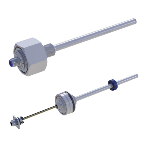
  9. novotechnik TLM 102 Series User manual

novotechnik TLM 102 Series User manual

Artikelnummer: 516966 / 07 Änderungen vorbehalten / Specifications subject ot change 2009/02 Seite 1
TLM Quadratur Gebrauchsanleitung
TLM Quadrature Instructions for Use
1 Allgemeine Beschreibung
Magnetostriktive Wegaufnehmer für direkte, genaue und
absolute Messung von Wegen bzw. Längen in der
Steuerungs-, Regelungs- und Messtechnik.
2 Sicherheitshinweise
2.1 Bestimmungsgemäße Verwendung
Der Wegaufnehmer TLM wird zu seiner Verwendung in
eine Maschine oder Anlage eingebaut. Er bildet zusammen
mit einer Steuerung ein Wegmesssystem und darf auch nur
für diese Aufgabe eingesetzt werden.
Bei unbefugten Eingriffen, unzulässiger Anwendung oder
Nichtbeachtung der Montagehinweise kommt es zum
Verlust von Garantie- und Haftungsansprüchen.
2.2 Installation und Inbetriebnahme
Der Wegaufnehmer ist nur von Fachpersonal und unter
Berücksichtigung aller geltenden Sicherheitsbestimmungen
in Betrieb zu nehmen.
Alle Maßnahmen zum Schutz von Personen bei einem
Defekt des Wegaufnehmers müssen vor der
Inbetriebnahme getroffen werden.
Starke magnetische oder elektromagnetische Felder in
unmittelbarer Nähe zum Wegaufnehmer können zu
fehlerhaften Signalen führen!
2.3 Anschlüsse prüfen
Falsche Verbindungen und Überspannung können zur
Beschädigung des Wegaufnehmers führen.
Prüfen Sie deshalb vor dem Einschalten die Anschlüsse
immer sorgfältig.
Achtung: Potentialdifferenzen zwischen Versorgung GND
und Signal GND sind zu vermeiden.
Durch Potentialdifferenzen zwischen Versorgung GND und
Signal GND kann der Wegaufnehmer zerstört werden!
2.4 Einschalten des Systems
Bitte beachten Sie, dass das System beim Einschalten
unkontrollierte Bewegungen ausführen kann, vor allem
wenn die Wegmesseinrichtung Teil eines Regelsystems ist,
dessen Parameter noch nicht eingestellt sind. Stellen Sie
daher sicher, dass hiervon keine Gefahren ausgehen
können.
2.5 Messwerte prüfen
Nach dem Austausch eines Wegaufnehmers wird
empfohlen, die Ausgangswerte in der Anfangs- und
Endstellung des Positionsgebers im Handbetrieb zu
überprüfen. (Änderungen oder fertigungsbedingte
Streuungen vorbehalten)
2.6 Funktionsfähigkeit prüfen
Die Funktionsfähigkeit des Wegmesssystems und aller
damit verbundenen Komponenten ist regelmäßig zu
überprüfen und zu protokollieren.
2.7 Funktionsstörung
Wenn das Wegmesssystem nicht ordnungsgemäß arbeitet,
ist es außer Betrieb zu nehmen und gegen unbefugte
Benutzung zu sichern.
1 General description
This device is a magnetostricitve transducer for direct,
precise and absolute measurement of displacements or
lengths in control, regulation and measuring applications.
2 Safety instructions
2.1 Conventional application
The TLM transducer is intended to be installed in a machine
or system. Together with a controller it comprises a position
measuring system and may only be used for this purpose.
In case of unauthorized modifications, non-permitted usage
or non-observance of installation instructions, the warranty
and liability claims will be lost.
2.2 Installation and startup
The transducer must be installed by qualified personnel in
consideration of all relevant safety regulations.
Non-observance of the installation instructions will void any
warranty or liability claims.
All personal protection measures in case of a transducer
defect or failure must be taken before startup.
Strong magnetic or electromagnetic fields in close
vicinity to the linear transducer may lead to faulty
readings!
2.3 Check connections
Improper connections and overvoltage can damage the
transducer.
Please always check the connections carefully before
turning on the system.
Caution: Potential differences between supply voltage
GND and signal GND must be avoided.
With different potentials between supply voltage GND and
signal GND the transducer can be destroyed!
2.4 Turning on the system
Please note that the system may execute uncontrolled
movements when first turned on or when the transducer is
part of a closed-loop system whose parameters have not
yet been set. Therefore make sure that no hazards can
result from these situations.
2.5 Check output values
After replacing or repairing a transducer, it is advisable to
verify the output values for the start and end position of the
position marker in manual mode. (Transducers are subject
to modification or manufacturing tolerances)
2.6 Check functionality
The functionality of the transducer system and all its
associated components should be regularly checked and
recorded.
2.7 Fault conditions
If the transducer system doesn‘t operate properly, it should
be taken out of service and protected against unauthorized
use.
Artikelnummer: 516966 / 07 Änderungen vorbehalten / Specifications subject ot change 2009/02 Seite 2
TLM Quadratur Gebrauchsanleitung
TLM Quadrature Instructions for Use
3 Einbau / Installation
3.1 Wegaufnehmer / Transducer
Beispiel Teileschlüssel / example ordering code:
TLM xxxx 001 xxx xxx
85
Elektrischer Nullpunkt
electrical zero point
L
Zubehör / accessories:
Positionsgeber / position marker
Z-TLM-P01
75
15
37,5
50
65
M5
38
Markierung / marks
Elektrischer Nullpunkt / electrical zero point
Zubehör: Positionsgeber /
Accessories: position marker
Z-TLM-P01, Art.-Nr. / P/N 005651
je Schraube max. 200 Ncm /
Tighten to max. 200 Ncm (=283 ozf in)
Spannklammern und Spannschrauben im Beipack enthalten /
Mounting clamps and screws included
Artikelnummer: 516966 / 07 Änderungen vorbehalten / Specifications subject ot change 2009/02 Seite 3
TLM Quadratur Gebrauchsanleitung
TLM Quadrature Instructions for Use
13 85
M12x1
13,5 85
M16x0,75
3.2 Elektrischer Anschluss / Electrical connection
3.2.1 Code 102
3.2.2 Code 112
3.2.3 Code 201
Artikelnummer: 516966 / 07 Änderungen vorbehalten / Specifications subject ot change 2009/02 Seite 4
TLM Quadratur Gebrauchsanleitung
TLM Quadrature Instructions for Use
3.3.3 Z-TLM-P05
3.3 Positionsgeber / Position marker
3.3.1 Z-TLM-P01
3.3.2 Z-TLM-P04
85,5 45
22
Markierung
Marker
M5x10
±18°
37,4
57
64
Elektrischer Nullpunkt
electrical zero point
20
55
45
28
±15
15
∅4,2
57 +11
84,5 21
Elektrischer Nullpunkt
electrical zero point
∅4,2
4,3
85 20
36,5
28
±2
0 - 4
Elektrischer Nullpunkt
electrical zero point
11,5
50 +4
Artikelnummer: 516966 / 07 Änderungen vorbehalten / Specifications subject ot change 2009/02 Seite 5
TLM Quadratur Gebrauchsanleitung
TLM Quadrature Instructions for Use
3.4 Elektrische Daten / Electrical data
Versorgungsspannung / Supply voltage: 24 VDC ±20%
Stromaufnahme / Current draw: Quadratur Schnittstelle / Quadrature interface ≤100 mA typisch / typical
3.5 Steckerbelegung / Pin configuration
( Sicht auf den Flanschstecker / front view to the flange connector )
8-pol. Flanschstecker / 8-pin flange connector
M12x1, DIN EN 50044
Beispiel Teileschlüssel / example ordering code: TLM xxxx xxx xxx 102
Zubehör / accessories : Kupplungsdose / straight connector EEM 33-86; IP67; Art.-Nr. / P/N 005629
Winkeldose / angled connector
EEM 33-87; IP67; Art.-Nr. / P/N 005630
Flanschstecker 12-pol. / 12 pin flange connector
IEC130-9, DIN 45326
Beispiel Teileschlüssel / example ordering code: TLM xxxx xxx xxx 112
Zubehör / accessories : Kupplungsdose / straight connector EEM 33-62; IP67; Art.-Nr. / P/N 005609
Winkeldose / angled connector
EEM 33-63; IP67; Art.-Nr. / P/N 005610
Spezifische Stecker auf Anfrage / Special connectors on request :
( Sicht auf den Flanschstecker / front view to the flange connector )
Artikelnummer: 516966 / 07 Änderungen vorbehalten / Specifications subject ot change 2009/02 Seite 6
TLM Quadratur Gebrauchsanleitung
TLM Quadrature Instructions for Use
Spezifischer Stecker auf Anfrage / Special connector on request
Beispiel Teileschlüssel: TLM xxxx xxx 8xx 112
Example ordering code :
TLM xxxx xxx 8xx 112
Stecker / Plug
Code 112
Signal
PIN A A +
PIN B B +
PIN C B -
PIN D Z +
PIN E Z -
PIN F Versorgung GND /
supply voltage GND
PIN G +24 VDC
PIN H A -
PIN J Teach-In
PIN K Power-On-Burst
PIN L n.c.
PIN M n.c.
3.6 Quadratur Schnittstelle / Quadrature interface
Beispiel Teileschlüssel: TLM xxxx xxx 8xx 102
Example ordering code :
TLM xxxx xxx 8xx 102
Stecker / Plug
Code 102
Kabel / Cable
Code 201, 203, 205
Dose m. Kabel /
Connector w. Cable
EEM33-86, EEM33-87
Signal
PIN 1 YE gelb / yellow WH weiss / white A +
PIN 2 GY grau / grey BN braun / brown B +
PIN 3 GN grün / green GN grün / green B -
PIN 4 WH weiss / white YE gelb / yellow Z +
PIN 5 RD rot / red GY grau / grey Z -
PIN 6 BU blau / blue PK rosa / pink Versorgung GND /
supply voltage GND
PIN 7 BN braun / brown BU blau / blue +24 VDC
PIN 8 PK rosa / pink RD rot / red A -
ACHTUNG ! Konfektionierte Kabel können abweichende Farbbelegung aufweisen !
CAUTION ! Customized cables may show different color coding !
ACHTUNG ! Konfektionierte Kabel können abweichende Farbbelegung aufweisen !
CAUTION ! Customized cables may show different color coding !
Artikelnummer: 516966 / 07 Änderungen vorbehalten / Specifications subject ot change 2009/02 Seite 7
TLM Quadratur Gebrauchsanleitung
TLM Quadrature Instructions for Use
3.7 Arbeitsweise der inkrementellen Schnittstelle
Inkrementelle Wegaufnehmer erzeugen üblicherweise 2
Signalpulse, welche um 90°zueinander phasenversetzt sind
(A / B Signal). Der Ausdruck „Quadratur“ bezieht sich auf
diesen 90°-Phasenversatz. Ein absolut messender
Wegaufnehmer muss seinen Positionswert in eine Anzahl
Pulse „übersetzen“, welche dem zurückgelegten Weg
entspricht.
A eilt B vor bei positiver Bewegung (Positionsgeber bewegt
sich vom Anschlussflansch weg), bzw. B eilt A vor bei
negativer Bewegung.
Ein zusätzliches Referenzsignal Z wird für die Nullstellung der
Steuerung zur Verfügung gestellt.
Die Quadratur-Schnittstelle kann direkt mit handelsüblichen
Inkrementalencoder-Eingangsstufen der betroffenen
Steuerung verbunden werden.
Die Ermittlung des zurückgelegten Weges erfolgt
synchronisiert alle 62,5 µs. Die Pulsbreite der Quadratur-
Signale wird innerhalb dieses Refreshzyklus an die Anzahl
der zu übertragenden Pulse angepasst.
Z-Signal / Referenzfahrt
Bei überschreiten der Position 0 wird das Z-Signal für die
Dauer eines Inkrementes auf logisch „HIGH“ gesetzt. Das Z-
Signal kann zur Rücksetzung des Zählers in der Steuerung
genutzt werden. Nach der Zähler-Rücksetzung kann die
absolute Position durch eine einfache Aufwärts- / Abwärts-
Zählung ermittelt werden.
Fehlermeldungen
Bei fehlendem Positionsgeber (vertikaler oder lateraler
Abstand ausserhalb der erlaubten Werte) erkennt der
Weggeber TLM einen Fehler und sendet „0“ als Positionswert.
3.7 Principle of incremental interface
Incremental position transducers usually generate two data
signals that are electrically 90°out of phase with each other
(A / B signal). The term „quadrature“ refers to this 90°phase
relationship. An absolute position from a transducer has to be
„translated“ into a relative movement represented by edges
where one edge or transition corresponds to the transducer
resolution.
A leads B by 90°for positive motion (position marker moving
away from connector) and B leads A for negative motion
(position marker moving towards the connector).
An additional reference signal named Z is available for
resetting the counter of the control system.
The quadrature output can be directly connected to standard
incremental encoder inputs of the control system.
The calculatio of the position difference is synchronized
internally each 62,5 µs (16kHz refresh). The pulse duration of
the quadrature signals is adopted to the number of pulses to
be transmitted in-between this refresh cycle.
Z signal and reference move
When the position is 0 or negative, the Z signal (zero
indication) is set to logical high. The Z signal can be used to
resent the position counter in the control system. After the
reset the absolute position can be determined by the control
system using a simple up/down counter.
Error conditions
If the position marker is missing (vertical distance to
transducer is too far or position is outside the specified
measuring range), the TLM detects an error and transmits „0“
as position value.
Artikelnummer: 516966 / 07 Änderungen vorbehalten / Specifications subject ot change 2009/02 Seite 8
TLM Quadratur Gebrauchsanleitung
TLM Quadrature Instructions for Use
4 Montagehinweis
Bei der Montage der Befestigungsklammern ist das maximale
Drehmoment zu beachten. Es wird empfohlen, den Abstand
zwischen 2 Befestigungsklammern auf maximal 1000 mm zu
beschränken.
Der Standard-Positionsgeber (Zubehör) wird im Abstand laut
3.3 zur Profiloberfläche montiert. Die Befestigung des freien
Positionsgebers erfolgt mit Schrauben M4. Bei Montage des
Positionsgebers ist auf eine ausreichende Ausrichtung
desselben zur Messrichtung zu achten.
Ein Potentialausgleich - Stromfluss - über den Kabelschirm ist
zu vermeiden. Der Kabelschirm ist mit dem Metallgehäuse
des Steckers verbunden – somit auch mit dem Gehäuse TLM.
Für kritische Applikationen stehen optional auch Kunstoff-
Befestigungsklammern zur Verfügung.
Der Bereich für den Kabelabgang muss ausreichend
dimensioniert werden, der Mindestbiegeradius ist
einzuhalten und scharfe Kanten sind zu vermeiden!
Versatz des Positionsgebers:
Ein Höhenversatz des Positionsgebers Z-TLM-P01
von 0 - 4 mm bewirkt eine Signaländerung
von ca. 200 µm/mm.
Ein Seitenversatz des Positionsgebers Z-TLM-P01 von bis zu
2 mm führt zu keiner Signaländerung.
Ein Höhenversatz des Positionsgebers Z-TLM-P04 von
4 - 15 mm bewirkt eine Signaländerung von ca. 150 µm/mm.
Ein Seitenversatz des Positionsgebers Z-TLM-P04 von bis zu
2 mm führt zu keiner Signaländerung, bei 2 -15 mm beträgt
die Signaländerung ca.15 µm/mm.
5 Anschlüsse
Beim elektrischen Anschluss unbedingt zu beachten:
Anlage (Versorgung GND) und Schaltschrank (Signal GND)
müssen auf gleichem Potential liegen.
Um die elektromagnetische Verträglichkeit (EMV) zu
gewährleisten, sind nachfolgende Hinweise unbedingt zu
beachten:
• Wegaufnehmer und Steuerung müssen mit einem
geschirmten Kabel verbunden werden.
• Schirmung: Geflecht aus Kupfer-Einzeldrähten,
85% Bedeckung.
• Auf der Seite der Steuerung muss der Kabelschirm geerdet,
d.h. mit dem Schutzleiter verbunden werden.
4 Installation Instructions
Note the maximum tightening torque when fastening down the
mounting clamps. Recommended maximum distance between
2 mounting clamps is 1000 mm (40 inches).
The position marker (order separately) is installed at a distance
according to 3.3 from the top surface of the transducer. The
floating position marker is attached using M4 screws. When
installing the position marker, observe proper orientation of the
position marker to the direction of travel.
Avoid ground loops through the cable shield. Connect the
shield to the metal body of the connector, which in turn
provides contact to the transducer housing.
For critical applications optionally also plastic mounting clamps
are available.
For the area of the cable please take care that enough
space is available, the minimum bending radius has been
observed and sharp edges have be avoided.
Displacement of the position marker:
A horizontal displacement of the position marker Z-TLM-P01 of
0 - 4 mm causes a change of signal of approx.
200 µm/mm.
A vertical displacement of the position marker Z-TLM-P01 of
up to 2 mm leads to no change of signal.
A horizontal displacement of the position marker Z-TLM-P04 of
4 - 15 mm causes a change of signal of approx.
150 µm/mm.
A vertical displacement of the position marker Z-TLM-P04
of up to 2 mm leads to no change of signal, from 2 - 15 mm the
change of signal amounts to approx.15 µm/mm.
5 Wiring
Note the following when making electrical connections:
System (supply voltage GND) and control cabinet (signal
GND) must be at the same potential.
To ensure the electromagnetic compatibility, the following
instructions must be strictly followed:
• Transducer and controller must be connected using shielded
cable.
• Shielding: Copper filament braided, 85% coverage.
• On the controller side the shield must be tied to the connector
housing in the BKS connector.
Artikelnummer: 516966 / 07 Änderungen vorbehalten / Specifications subject ot change 2009/02 Seite 9
TLM Quadratur Gebrauchsanleitung
TLM Quadrature Instructions for Use
TLM xxxx xxx xxx xxx
Elektrisch definierter Bereich /
defined electrical range
Mechanische Ausführung /
mechanical configuration
Elektrische Schnittstelle /
electrical interface
Elektrischer Anschluss/
electrical connection
8 Bestellcode / ordering code
6 Zubehör (separat zu bestellen)
• Kupplungsdose 8-pol. M12x1 mit 2m Kabel
(EEM 33-86 IP 67; Art.Nr. 005629)
• Winkeldose 8-pol. M12x1 mit 2m Kabel
(EEM 33-87 IP 67; Art.Nr. 005630)
• Kupplungsdose 12-pol. IEC130-9
(EEM 33-62 IP 67; Art.Nr. 005609)
• Winkeldose 12-pol. IEC130-9
(EEM 33-63 IP 67; Art.Nr. 005610)
• Positionsgeber Z-TLM P01 (Art.Nr. 005651)
• Positionsgeber Z-TLM P04 (Art.Nr. 005654)
• Geführter Positionsgeber Z-TLM P05 (Art.Nr. 005655)
6 Accessories (order separately)
• Straight connector 8-pin M12x1 with cable, 2m
(EEM 33-86 IP 67; P/N 005629)
• Angled connector 8-pin M12x1 with cable, 2m
(EEM 33-87 IP 67; P/N 005630)
• Straight connector 12-pin IEC130-9
(EEM 33-62 IP 67; P/N 005609)
• Angled connector 12-pin IEC130-9
(EEM 33-63 IP 67; P/N 005610)
• Position marker Z-TLM P01 (P/N 005651)
• Position marker Z-TLM P04 (P/N 005654)
• Guided position marker Z-TLM P05 (P/N 005655)
7 Sonderzubehör auf Anfrage
• 2 Kunststoff-Befestigungsklammern
(Art.Nr. 056027)
• 3 Kunststoff-Befestigungsklammern
(Art.Nr. 056028)
7 Special accessories on request
• 2 plastic mounting clamps
(P/N 056027)
• 3 plastic mounting clamps
(P/N 056028)

This manual suits for next models

3

Other novotechnik Transducer manuals

novotechnik LWX Series User manual

novotechnik

novotechnik LWX Series User manual

novotechnik TIM Series User manual

novotechnik

novotechnik TIM Series User manual

novotechnik TLH User manual

novotechnik

novotechnik TLH User manual

novotechnik TH1 Series User manual

novotechnik

novotechnik TH1 Series User manual

novotechnik LWG Series User manual

novotechnik

novotechnik LWG Series User manual

novotechnik PTP Series User manual

novotechnik

novotechnik PTP Series User manual

novotechnik Z-TF1-PO1 User manual

novotechnik

novotechnik Z-TF1-PO1 User manual

novotechnik RSM-2800 User manual

novotechnik

novotechnik RSM-2800 User manual

novotechnik TMI Series User manual

novotechnik

novotechnik TMI Series User manual

novotechnik TM1 Series User manual

novotechnik

novotechnik TM1 Series User manual

novotechnik TX2 Series User manual

novotechnik

novotechnik TX2 Series User manual

novotechnik TP1 Series User manual

novotechnik

novotechnik TP1 Series User manual

novotechnik TIM Series User manual

novotechnik

novotechnik TIM Series User manual

novotechnik LS1 Series User manual

novotechnik

novotechnik LS1 Series User manual

novotechnik RSM-2800 User manual

novotechnik

novotechnik RSM-2800 User manual

novotechnik RFC-4800 CAN User manual

novotechnik

novotechnik RFC-4800 CAN User manual

novotechnik TM1 Series User manual

novotechnik

novotechnik TM1 Series User manual

novotechnik TH1 CANopen User manual

novotechnik

novotechnik TH1 CANopen User manual

novotechnik T Series User manual

novotechnik

novotechnik T Series User manual

novotechnik TH1 Series User manual

novotechnik

novotechnik TH1 Series User manual

novotechnik TEX Series User manual

novotechnik

novotechnik TEX Series User manual

novotechnik RSC-2800 User manual

novotechnik

novotechnik RSC-2800 User manual

Popular Transducer manuals by other brands

Omega PX276 instruction sheet

Omega

Omega PX276 instruction sheet

controlair 500-AA Installation, operation and maintenance instructions

controlair

controlair 500-AA Installation, operation and maintenance instructions

W.E. Anderson 2800 Series Installation and operating instructions

W.E. Anderson

W.E. Anderson 2800 Series Installation and operating instructions

JBL Professional Series Technical manual

JBL

JBL Professional Series Technical manual

Airmar Technology Corporation R99 owner's guide

Airmar Technology Corporation

Airmar Technology Corporation R99 owner's guide

Thyracont VSP63MA4 operating instructions

Thyracont

Thyracont VSP63MA4 operating instructions

DSPM UniMeasure HX-VP420 Series installation guide

DSPM

DSPM UniMeasure HX-VP420 Series installation guide

Amprobe ACF-3000 SR operating instructions

Amprobe

Amprobe ACF-3000 SR operating instructions

NK TECHNOLOGIES VTD-BD Series instructions

NK TECHNOLOGIES

NK TECHNOLOGIES VTD-BD Series instructions

Cleco P2182BA/EN instruction manual

Cleco

Cleco P2182BA/EN instruction manual

TR-Electronic LMRI-46 200 ANA-I+JUSTAGE manual

TR-Electronic

TR-Electronic LMRI-46 200 ANA-I+JUSTAGE manual

Veris Hawkeye H421SP installation guide

Veris

Veris Hawkeye H421SP installation guide

Soundmask SM-T-1200 operating manual

Soundmask

Soundmask SM-T-1200 operating manual

Airmar CM599LH Owner's guide and installation instructions

Airmar

Airmar CM599LH Owner's guide and installation instructions

Simrad ES38-12 -  REV C Installation

Simrad

Simrad ES38-12 - REV C Installation

Omega RH62 Series manual

Omega

Omega RH62 Series manual

Humminbird XNT 9 DB 74 T installation guide

Humminbird

Humminbird XNT 9 DB 74 T installation guide

Ningbo KPT-G1210 manual

Ningbo

Ningbo KPT-G1210 manual

manuals.online logo
manuals.online logoBrands
  • About & Mission
  • Contact us
  • Privacy Policy
  • Terms and Conditions

Copyright 2025 Manuals.Online. All Rights Reserved.