Meggitt Whittaker C173255-1 User manual

NOTICE: PROPRIETARY INFORMATIONOF WHITTAKER CONTROLS,INC., A BUSINESS UNIT OF MEGGITT PLC.
THE INFORMATION CONTAINED IN THIS DOCUMENT IS DISCLOSED IN CONFIDENCE. IT IS THE PROPERTY OF
WHITTAKER CONTROLS, AND SHALL NOT BE USED, DISCLOSED TO OTHERS, OR REPRODUCED IN WHOLE
OR IN PART WITHOUT THE EXPRESS WRITTEN CONSENT OF WHITTAKER CONTROLS. IF CONSENT IS GIVEN
THIS NOTICE SHALL APPEAR IN ANY SUCH REPRODUCTION.
REVISION 2.1 – 04/01/2004
Maintenance Manual
ABSOLUTE PRESSURE
TRANSDUCER ASSEMBLY
PART NUMBERS:
C173255-1
C173255-2
C173255-3
C173255-4

WHITTAKER CONTROLS, INC.
A MEGGITT PLC COMPANY
MAINTENANCE MANUAL
ABSOLUTE PRESSURE TRANSDUCER ASSEMBLY
C173255
INDUSTRIAL PRODUCTS GROUP Revision 2.1 04/01/2004 Page A
LIST OF EFFECTIVE PAGES
On a revised page, the portion of text or illustrations affected by the change is indicated by a vertical line
in the outer margin of thepage. When a revision is issued, the entire document is reissued with the current
revision number and date shown on all pages. For major revisions, the basic number is incremented. For
minor revisions, the number following the decimal is incremented. Dates of issue for original and subse-
quent revisions are as follows:
Original ..............................................05/01/1998
Revision 2.0 ...........................................09/01/2003
Revision 2.1 ...........................................04/01/2004
The total number of pages in this technical document is 17 consisting of the following:
Title, A, 1 – 15
TABLE OF CONTENTS
SUBJECT PAGE
Introduction .......................................................................4
Description and Operation ...........................................................7
Installation ......................................................................10
Fault Isolation ....................................................................11
Repair ..........................................................................13
Maintenance Parts List .............................................................15
LIST OF ILLUSTRATIONS
FIGURE PAGE
1 Absolute Pressure Transducer Assembly .......................................8
2 Interconnection Diagram ...................................................12

WHITTAKER CONTROLS, INC.
A MEGGITT PLC COMPANY
MAINTENANCE MANUAL
ABSOLUTE PRESSURE TRANSDUCER ASSEMBLY
C173255
INDUSTRIAL PRODUCTS GROUP Revision 2.1 04/01/2004 Page 1
LIST OF TABLES
TABLE PAGE
1 Specifications and Characteristics .............................................6
2 Leading Particulars .........................................................9
3 Recommended Spare Parts .................................................15
IMPORTANT SAFETY INSTRUCTIONS
SAVE THESE INSTRUCTIONS!
This manual contains important instructions that should be followed during installation and maintenance
of the Absolute Pressure Transducer Assembly (transducer assembly). The following are general safety
precautions that arenot related to specific procedures andtherefore do not appear elsewhere in this publi-
cation. These are recommended precautions that personnel must understand and apply during many
phases of maintenance.
Safety Alert Symbols
Safetyalert symbolsareused inthismanual toidentifypotential orimmediatepersonalinjury hazards.The
safety alert symbol words are explained below:
DANGERindicatesanimminentlyhazardoussituationwhich,ifnot
avoided, will result in injury or serious injury.
WARNINGindicatesa potentiallyhazardous situationwhich,if not
avoided, could result in injury or serious injury.
CAUTION indicates a potentially hazardous situation which, if not
avoided, may result in minor or moderate injury.
CAUTION used without the safety alert symbol indicates a poten-
tially hazardous situation which, if not avoided, may result in pro-
perty damage.

WHITTAKER CONTROLS, INC.
A MEGGITT PLC COMPANY
MAINTENANCE MANUAL
ABSOLUTE PRESSURE TRANSDUCER ASSEMBLY
C173255
INDUSTRIAL PRODUCTS GROUP Revision 2.1 04/01/2004 Page 2
WEAR PROTECTIVE CLOTHING
!Wear protective clothing (gloves, apron, etc.) approved for the materials and tools being used.
USE APPROVED SAFETY EQUIPMENT
!When cleaners are being used, approved explosion-proof lights, blowers, and other equipment must
be used. Make sure that fire fighting equipment is readily available and in working order.
GIVE CLEANERS SPECIAL CARE
!Keepcleaners inspecialpolyethylenebottlesorinsafetycansandinminimumquantities. Discardsoil-
ed cleaning rags into safety cans.
Equipment Safety Information
The following safety information briefly discusses hazards peculiar to the equipment, whichare likely to be
encountered during maintenance activity.
GENERAL OPERATING LOCATION PRECAUTIONS
!Use only authorized replacement parts or hardware.
!Observe proper Lock-Out/Tag-Out procedures when working on the transducer assembly and make
sure that personnel protection equipment such as electrical grounds are installed.
!Make sure that all of the electrical wiring is properly terminated. Make sure that all of the wire terminals
are securely connected.
!Avoid hazardous voltage situations that can result from unsafe conditions such as, but not limited to
the following:
CImproper grounding
CHandling electrical leads or devices with wet hands or on wet ground
CDamaged electrical wire insulation
CImproper connection or re-connection of the power terminals.
CShort circuits to ground

WHITTAKER CONTROLS, INC.
A MEGGITT PLC COMPANY
MAINTENANCE MANUAL
ABSOLUTE PRESSURE TRANSDUCER ASSEMBLY
C173255
INDUSTRIAL PRODUCTS GROUP Revision 2.1 04/01/2004 Page 3
OPERATION AND MAINTENANCE NEAR HIGH PRESSURE COMPRESSED GAS SYSTEMS
!Protect all gas lines from damage or puncture. Do not operate the equipment if a gas leak is detected
– this could indicate a loose or damaged high pressure fitting.
!Do not use flammable solvents for cleaning parts.
!Check for tools, rags, or loose parts left in the area before resuming operation.

WHITTAKER CONTROLS, INC.
A MEGGITT PLC COMPANY
MAINTENANCE MANUAL
ABSOLUTE PRESSURE TRANSDUCER ASSEMBLY
C173255
INDUSTRIAL PRODUCTS GROUP Revision 2.1 04/01/2004 Page 4
INTRODUCTION
1. Purpose of Manual
A. This technical manual contains instructions for operation and maintenance of the Absolute
PressureTransducerAssembly(transducerassembly).Thismanualisintendedtoprovideinfor-
mation in sufficient detail to permit proper fault isolation, maintenance, and repair of the equip-
ment.
B. The transducer assembly is a component of a fuel metering system used in conjunction with
the General Electric Engine Control System to control delivery of natural gas to individual com-
bustor manifolds of a Gas Turbine Engine. Refer to Table 1 for specifications and characteris-
tics.
2. Revision Service
This manual will be revised as necessary to show the current information.
3. Weights and Measurements
Weights and measurements in this manual are expressed in both English (U.S. customary) and
Metric (SI) units.
4. Scope of Manual
The technical manual is divided as follows:
Introduction – Describes the purpose and scope of this manual.
DescriptionandOperation–Containsaphysicaldescriptionoftheequipmenttogetherwithexplan-
ations of its operation and component functions and characteristics.
Installation – Provides information for installing, connecting, and preparing the equipment for use.
Fault Isolation – Contains procedures for finding the cause of a malfunction.
Repair – Provides instructions for replacement of defective components.

WHITTAKER CONTROLS, INC.
A MEGGITT PLC COMPANY
MAINTENANCE MANUAL
ABSOLUTE PRESSURE TRANSDUCER ASSEMBLY
C173255
INDUSTRIAL PRODUCTS GROUP Revision 2.1 04/01/2004 Page 5
Maintenance Parts List – Contains a list of spare parts recommended for on-site support of the
equipment.
5. Symbols and Abbreviations
Symbols and abbreviations used in this technical manual are as follows:
AWG American Wire Gage
C Centigrade (Celsius)
DC Direct current
F Fahrenheit
Hz Hertz
kg Kilogram
kg/s Kilograms/second
kPa KiloPascal
kPad KiloPascal, differential
kPag KiloPascal, gage
LVDT Linear variable differential transformer
mm Millimeter
Nm Newton-meter
NPT National Pipe Thread
P/N Part Number
psi Pounds per square inch
psia Pounds per square inch, absolute
psid Pounds per square inch, differential
psig Pounds per square inch, gage
SPDT Single-pole, double-throw
VDC Volts direct current

WHITTAKER CONTROLS, INC.
A MEGGITT PLC COMPANY
MAINTENANCE MANUAL
ABSOLUTE PRESSURE TRANSDUCER ASSEMBLY
C173255
INDUSTRIAL PRODUCTS GROUP Revision 2.1 04/01/2004 Page 6
Table 1. Specifications and Characteristics
Applications ................................. General Electric LM1600, LM2500, LM2500+
and LM6000 Gas Turbine Engines
Service Fluid .......................................... Natural Gas (per MID-TD-0000-1)
Electrical Power ................................................ 12VDC (9 to 16 VDC)
Temperatures
Normal Ambient ....................................... –54 to 104°C (–65 to 220°F)
High Ambient (one hour) ........................................... 177°C (350°F)
Natural Gas ............................................. 0to149°C (32 to 300°F)
DESCRIPTION WHITTAKER
PART NUMBER HAZARDOUS AREA RATING
Absolute Pressure
Transducer Assembly C173255-1
C173255-2 Explosion Proof Design, CSA/UL, certified for NEC, Class
I, Division 1, Groups C and D, Temp Code T4 (maximim
ambient 120°C); CENELEC EEx d IIB, T4, Tamb = 120°C
C173255-3
C173255-4 Explosion Proof Design, CSA/UL, certified for NEC, Class
I, Division 1, Groups C and D, Temp Code T4 (maximum
ambient 120°C); CENELEC EEx d IIB, T4, Tamb = 120°C;
Group II, Category 2, Zone 1 (II 2 G) for ATEX

WHITTAKER CONTROLS, INC.
A MEGGITT PLC COMPANY
MAINTENANCE MANUAL
ABSOLUTE PRESSURE TRANSDUCER ASSEMBLY
C173255
INDUSTRIAL PRODUCTS GROUP Revision 2.1 04/01/2004 Page 7
DESCRIPTION AND OPERATION
1. System Operation
A. The fuel metering system is designed to provide the controlled flow of natural gas fuel to the
engine.
B. Afterthenatural gasinletsupplylineandthefuelmeteringvalveoutlet linesareconnected, and
the electrical connections are made, natural gas is applied to the fuel metering valve gas inlet
from the facility gas supply system. Fuel flow through the fuel metering system is initiated by
electrically commanding the fuel metering valve to open.
C. The fuel metering valve is opened as necessary to control the flow of natural gas fuel to the
individual engine combustor manifolds by modulating in response to position commands re-
ceived through the motor controller from the GE engine control system.
D. The position commands fromthe GE engine control system arederived from many parameters
suchasengineoperating conditions, gasproperties, gaspressuresandgastemperatures.The
use of an extensive valve characteristics map and accurate position feedback, accurately pro-
vides the desired mass flow rates of the natural gas into the individual combustor manifolds.
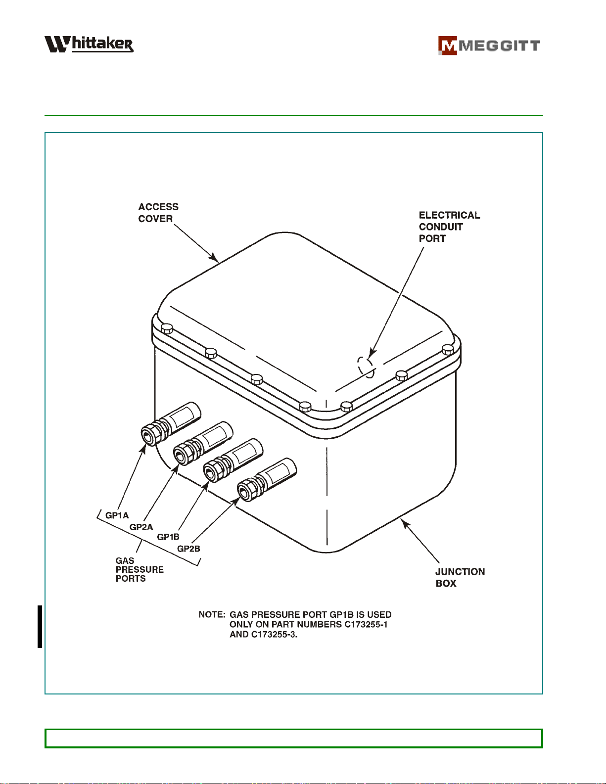
2. Absolute Pressure Transducer Assembly (See Figure 1)
A. When operating the engine, gas pressure at the inlet and outlet of each fuel metering valve is
monitoredbytheanabsolutepressuretransducer.Eachfuelmeteringvalvehasitsowndedica-
ted pressure transducer assembly, each of which includes three or four “smart” temperature
compensateddigitalabsolutepressuretransducersandtheircorrespondingelectronicinterface
circuit cards in one explosion proof enclosure.
B. Depending on system upstream piping geometry, one or two transducers are provided in each
assembly for upstream pressure measurement (GP1) and two transducers are provided for re-
dundant downstream pressures (GP2). For systems requiring two upstream pressure trans-
ducers, Whittaker Controls P/N C173255-1 is used; or P/N C173255-3 for European CE com-
pliance.Forsystemsrequiringasingleupstreamtransducer,WhittakerControlsP/NC173255-2
is used; or P/N C173255-4 for European CE compliance. .
C. For pressure transducer characteristics and specifications, refer to Table 2.
WHITTAKER CONTROLS, INC.
A MEGGITT PLC COMPANY
MAINTENANCE MANUAL
ABSOLUTE PRESSURE TRANSDUCER ASSEMBLY
C173255
INDUSTRIAL PRODUCTS GROUP Revision 2.1 04/01/2004 Page 8
Figure 1. Absolute Pressure Transducer Assembly

WHITTAKER CONTROLS, INC.
A MEGGITT PLC COMPANY
MAINTENANCE MANUAL
ABSOLUTE PRESSURE TRANSDUCER ASSEMBLY
C173255
INDUSTRIAL PRODUCTS GROUP Revision 2.1 04/01/2004 Page 9
3. Leading Particulars (Refer to Table 2)
Table 2
Leading Particulars
Type .......................................Digital pressure transducers and interface
electronics in explosion proof enclosure
Service Fluid ....................................... Natural Gas (per MIL-TD-0000-1)
Pressure Ports ............................. 3/8-inch tube, 3 places (compression fitting)
Pressures
Calibrated .......................................... 0to5170 kPa (0 to 750 psia)
Over-Pressure ........................................... 13800 kPa (2000 psia)
Accuracy ..................................................... ±0.02% of full scale
Temperatures
Fluid .............................................. –54 to +121/C (–65 to 250°F)
Ambient (maximum) ............................................... 82
/C (180°F)
Electrical Data
Voltage (normal) .......................................................12VDC
Voltage Range .................................................... 9to16VDC
Current ....................................................... 10milliamperes
Electrical Connections ........................ Terminal Block (¾-inch NPT conduit entry)
Dry Weight ................................................. 17.5 kg (38.5 pounds)

WHITTAKER CONTROLS, INC.
A MEGGITT PLC COMPANY
MAINTENANCE MANUAL
ABSOLUTE PRESSURE TRANSDUCER ASSEMBLY
C173255
INDUSTRIAL PRODUCTS GROUP Revision 2.1 04/01/2004 Page 10
INSTALLATION
1. General
This section contains information on installation and interfacing of the transducer assembly with the
engine and the GE engine control system.
2. Installation
A. Pressure Ports
The gas pressure ports are standard ¾-inch compression tube fittings in accordance the appli-
cable ANSI standards.
B. Pressure Ports
The gas pressure ports are standard ¾-inch compression tube fittings in accordance the appli-
cable ANSI standards.
C. Electrical Interfaces
Hard wiring to terminal strips, conduit, conduit connectors.
D. Shielding
The shields on all of the cabling must be open at the device end and tied to the shield bar at the
GE engine control system interface, or tied to a common ground at the motor controller.
E. Cable Entries
Allofthecable entries intotheenclosure mustbedoneusingmethodsapproved by local certifi-
cation agencies (i.e., CENELEC, CSA, FM, etc.).
F. Cable Wire Sizing
All customer cabling conductors must be 18 AWG.

WHITTAKER CONTROLS, INC.
A MEGGITT PLC COMPANY
MAINTENANCE MANUAL
ABSOLUTE PRESSURE TRANSDUCER ASSEMBLY
C173255
INDUSTRIAL PRODUCTS GROUP Revision 2.1 04/01/2004 Page 11
FAULT ISOLATION
1. General
Thissectioncontainsspecificchecksrequiredtofaultisolatethetransducerassemblyduringservice.
The first step in fault isolation is to verify the electrical connections. Make sure that all of the con-
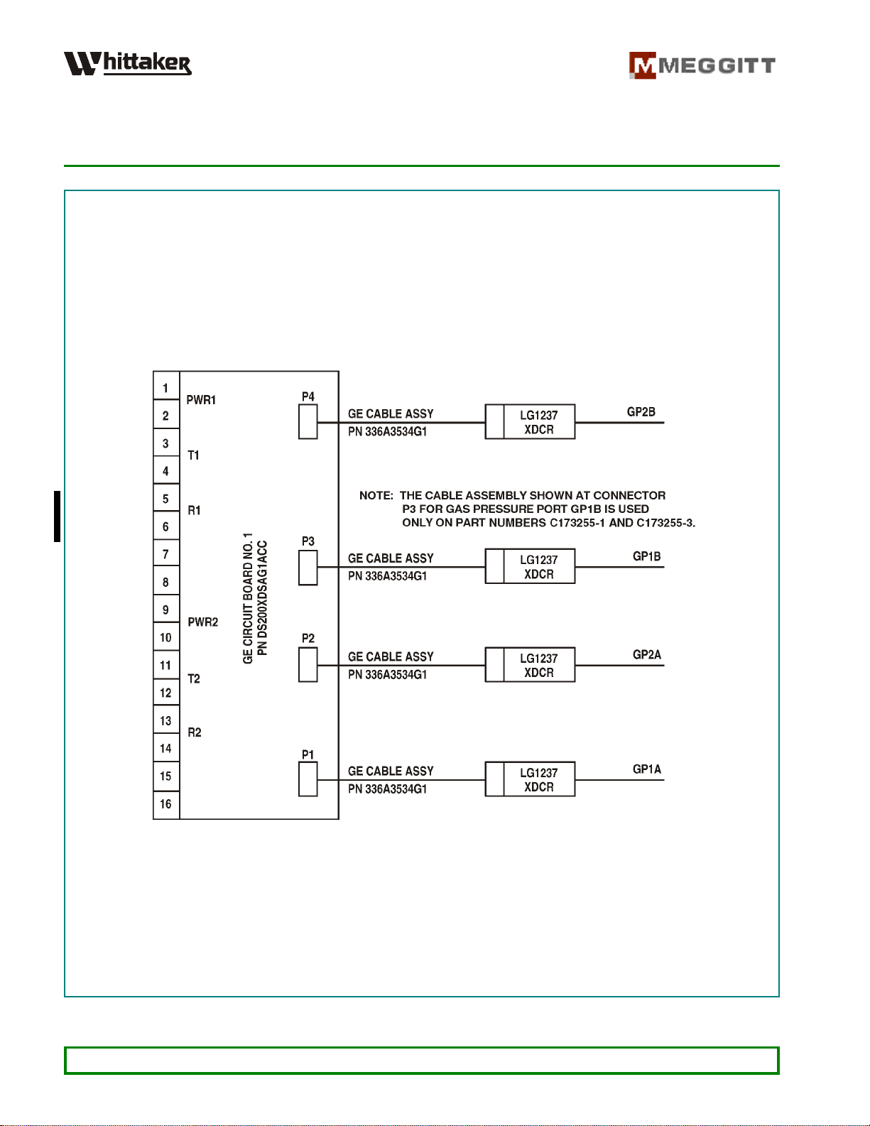
nections are secure and that there are no damaged conductors. Refer to Figure 2 for the electrical
interconnectiondiagram.Iftheconnectionsareallintact,performcomponentfaultisolationinaccord-
ance with the following paragraphs.
2. Pressure Transducers (GP1/GP2)
If the outputs of the redundant GP2A and GP2B transducers, or the GP1A and GP1B (where appli-
cable) inlet pressure transducers from any of the three input branches vary from each other by an
amount that exceeds the allowed limits, a fault will be registered by the GE engine control system.
Since these pressure transducers are not adjustable, the fault can only be isolated to the transducer
or printed circuit board. To isolate a defective pressure transducer or printer circuit board, the follow-
ing procedure should be performed.
A. Therearethreeorfourtransducerchannelsineachpressuretransducer assembly.Ifthesignal
ofonechannelissuspect,openthetransducerenclosureandinterchangetheconnector onthe
printed circuit card of the suspect channel with the adjacent channel printed circuit card (i.e.,
if channel GP2B is suspect, disconnect its cable from terminal P4 and reconnect it to terminal
P2).
B. If the suspect signal follows to the adjacent channel, the problem has been isolated to the
pressure transducer and the pressure transducer must be replaced.
C. Ifthesuspectsignalremainsonthesamechannel,theproblemhasbeenisolated totheprinted
circuit board and the printed circuit board must be replaced.
WHITTAKER CONTROLS, INC.
A MEGGITT PLC COMPANY
MAINTENANCE MANUAL
ABSOLUTE PRESSURE TRANSDUCER ASSEMBLY
C173255
INDUSTRIAL PRODUCTS GROUP Revision 2.1 04/01/2004 Page 12
Figure 2. Interconnection Diagram

WHITTAKER CONTROLS, INC.
A MEGGITT PLC COMPANY
MAINTENANCE MANUAL
ABSOLUTE PRESSURE TRANSDUCER ASSEMBLY
C173255
INDUSTRIAL PRODUCTS GROUP Revision 2.1 04/01/2004 Page 13
REPAIR
1. General
A. This section outlines specific repair tasks which may be required, as determined by the results
of performing fault isolation procedures. Prior to any repair action, perform the fault isolation
procedures (refer to FAULT ISOLATION).
B. Refer to Figure 2 for the system electrical wiring interconnection diagram.
2. Repair Tasks
A. Pressure Transducer Replacement
1) Removal
a. Disconnect the cable assembly from the pressure transducer by loosening the two
connector screws.
b. Remove the screws and washers securing the pressure transducer to the mounting
block.
c. Remove and discard the packing between the pressure transducer and the mounting
block.
2) Installation
a. Install a new packing on the pressure port of the new pressure transducer, between
the pressure transducer and the mounting block.
b. Secure the pressure transducer to the mounting block with the screws and washers.
c. Connect the cable assembly to the pressure transducer and tighten the two attaching
screws.

WHITTAKER CONTROLS, INC.
A MEGGITT PLC COMPANY
MAINTENANCE MANUAL
ABSOLUTE PRESSURE TRANSDUCER ASSEMBLY
C173255
INDUSTRIAL PRODUCTS GROUP Revision 2.1 04/01/2004 Page 14
B. Circuit Board Replacement
1) Removal
a. Disconnect all (three or four) transducer cable assemblies from the circuit board.
b. Disconnectthecables connected tothe 32-pinconnector.Makesurethattheconnec-
tor terminations are marked on the cable, so that they can be easily reconnected
during installation.
c. Removethemountingscrewssecuring thecircuitboard,andremovethecircuitboard
from the enclosure.
2) Installation
a. Install circuit board in the enclosure and secure it with the screws and washers.
b. Connect the cables to their assigned pins of the 32 pin connector.
c. Connect the transducer cables to their assigned connectors of the circuit board.

WHITTAKER CONTROLS, INC.
A MEGGITT PLC COMPANY
MAINTENANCE MANUAL
ABSOLUTE PRESSURE TRANSDUCER ASSEMBLY
C173255
INDUSTRIAL PRODUCTS GROUP Revision 2.1 04/01/2004 Page 15
MAINTENANCE PARTS LIST
1. General
Thissection identifiespartsrecommended foron-site maintenanceoftransducer assembly. Allofthe
recommended items may be ordered from Whittaker Controls.
2. Maintenance Parts
Table 3 comprises a listing of spare parts recommended for on-site maintenance support of the
transducer assembly. Table 3. Recommended Spare Parts
ITEM
NUMBER PART NUMBER DESCRIPTION RECOMMENDED
QUANTITY
1 C325937-2 Transducer, Pressure 1
2 C326270-1 Circuit Board 1
3 C327371 Cable Assembly 2
4 M83248-1-010 Packing (transducer to manifold) 4
5 NAS1352C04-12 Screw (#4-40 x 0.75 inch long) (manifold attaching) 4
6 MS35338-135 Washer, Lock (#4) (manifold attaching) 4
7 C326462 Screw (circuit board attaching) 6
8 C326469 Washer, Lock (circuit board attaching) 6
This manual suits for next models
3
Table of contents
Other Meggitt Transducer manuals

Popular Transducer manuals by other brands


MG
MG 17CE instruction manual

Gossen MetraWatt
Gossen MetraWatt SINEAX DME 4 Series operating instructions

WIKA
WIKA F2301 operating instructions

Desoutter
Desoutter DLT Series Product instructions

Lumel
Lumel P300 User Manual & Quick Start

S+S Regeltechnik
S+S Regeltechnik AERASGARD RCO2 Operating and mounting instructions


