PH Series
Pressure Transducer – Wet Media
INSTALLATION INSTRUCTIONS
• Read instructions thoroughly prior to install
Applications shown are suggested means of installing sensors, but it is
the responsibility of the installer to ensure that the installation is in
compliance with all national and local codes and OSHA requirements.
Installation should be attempted only by individuals familiar with
proper installation techniques and with codes, standards, and proper
safety procedures for control installations. Warning: Do not use on
oxygen service, in an explosive/hazardous environment, or with
flammable/combustible media.
Install the PH Series in any stainless compatible media application.
Media must be compatible with 17-4 PH stainless steel.
A unique retainer bracket design eliminates the requirement for a
back-up wrench on the sensor fitting.
PH models can handle overload pressure of 2x’s maximum full scale
range. Burst pressure is 5x’s maximum full scale range.
CONFIGURATION
#Z102149-0I
OPERATION
Test Mode: Test mode overrides output to full-scale. If product is
configured for current (mA) operation, output will be
20.0 mA in test mode. If product is configured for
voltage (VDC) operation, output will be 5.0 VDC or
10.0 VDC in test mode. (depending on position of JP2
output span jumper.)
Status LED: Status LED glows green to indicate normal operation.
Status LED glows red to indicate overpressure. Status
LED flashes red to indicate other fault condition.
TARE (Zero): Press and hold the “TARE” push-button for 2 seconds or
provide contact closure on auxiliary “REMOTE TARE”
terminal to automatically reset output to zero
pressure. To protect the unit from accidental tare, this
feature is enabled only when detected pressure is
within 5% of factory calibration.
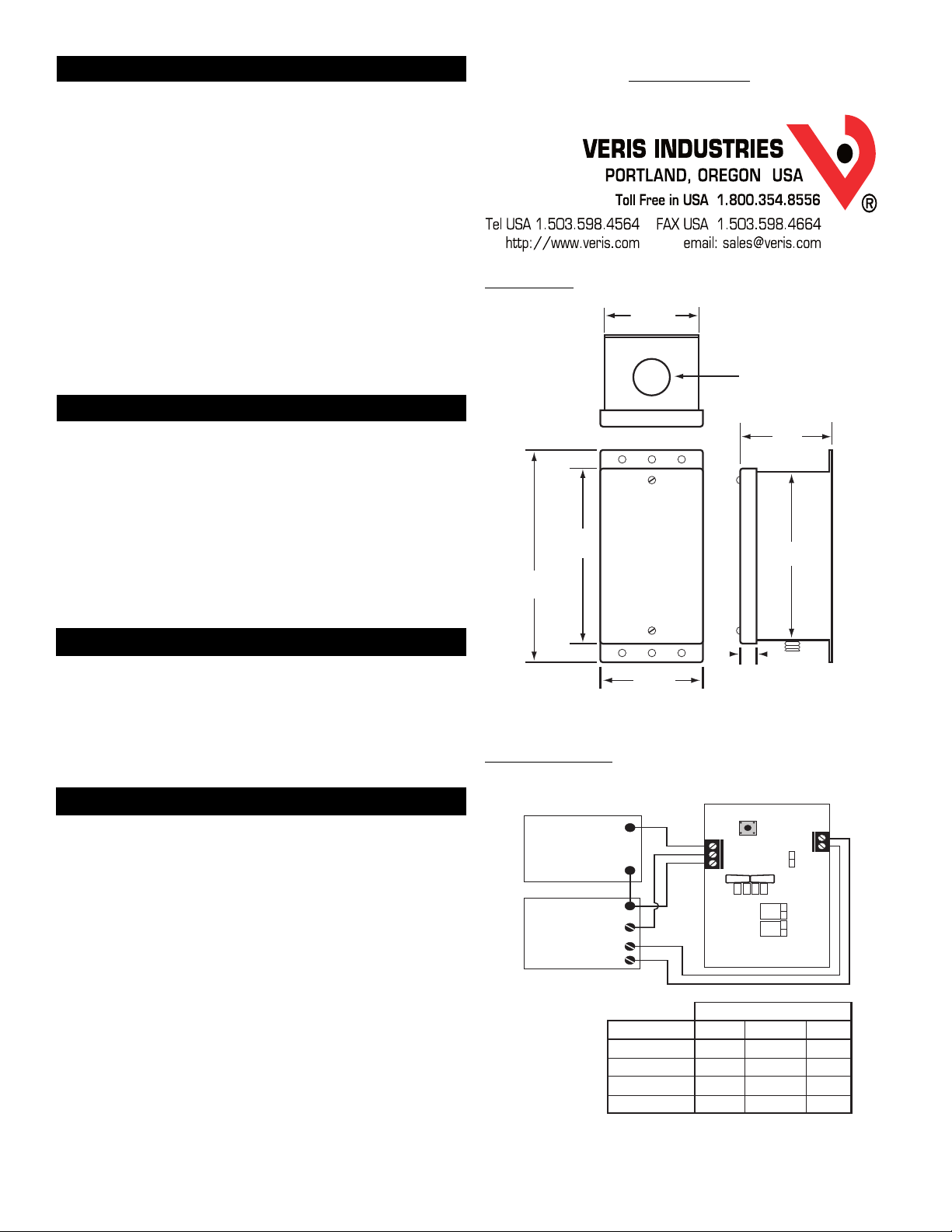
WIRING
Connect transmitter to control system and power supply as indicated.
Note: PH Series are 3-wire sourcing type transmitters.
CAUTION: This product utilizes a half-wave rectifier power supply. If a
transformer is to be used to power this product, the transformer must
not be used to power other devices utilizing non-isolated full-wave
power supplies.
OPTIONAL: Connect TARE (zero) terminals to digital output (contact
closure) of control system.
CAUTION: TARE input is for dry-contact. Do not apply voltage to TARE
(zero) terminals.
Use jumper JP1 to select voltage (V) or current (mA) mode.
Use jumper JP2 to select 0-10V or 0-5V output span. (Voltage mode only).
Use jumper JP3 to select slow or fast mode. Slow mode provides
5-second averaging for surge dampening.
Select appropriate full-scale range using the slide switch. WIRING DIAGRAM
1/4” NPT male thread,
stainless 17-4 PH
2.189"
(56 mm)
2.249"
(57mm)
.871" dia.
(22 mm)
.391"
(10mm)
4.176"
(106 mm) 4.0"
(102 mm)
5.06"
(129 mm)
2.445"
(62 mm)
DIMENSIONS
MODEL
07
08
09
10
A
25
62.5
125
250
B
50
125
250
500
C
100
250
500
1000
RANGE
+
-
-
POWERSUPPLY
12to 24 VDC/24 VAC
DIGITALCONTROL
AnalogInput
0-5V/0-10V
or4-20mA
Optional
Digital Output
VIN
OUT
COMMON
ZeroRemote
Zero
Slow
Fast
VOLT
mA
0-5
0-10
Response
Output
Range
TEST
A
B
C
VerisPS-24 Series


