DG Airparts Super XC User manual
Super XC
Instruction Manual
Version 1.0
READ THIS MANUAL FIRST!
and
DG Airparts, Inc.
present the

Introduction
Super XC
Page 2
Table of Contents
Introduction……………………………………………………………………………………………………….
Specifications……………………………………………………………………………………………………..
Disclaimer…………………………………………………………………………………………………………
Parts List…………………………………………………………………………………………………………..
Construction
Wing Part I………………………………………………………………………………………………
Wing Mount……………………………………………………………………………………………..
Stabilator…...……………………………………………………………………………………………
Fuselage Part I…………….……………………………………………………………………………..
Rudder…………………………………………………………………………………………………...
Wing Part II……………………………………………………………………………………………...
Fuselage Part II………………………………………………………………………………………….
Setup………………………………………………………………………………………………………………
Conclusion………………………………………………………………………………………………………..
2
2
2
3
6
9
11
13
14
18
19
21
21
Congratulations! You now own what we believe to the best and most complete high performance cross country
sailplane kit available anywhere today. The Super XC is a high performance cross country sailplane using the lat-
est RnR products molding technologies. The Super XC incorporates full-span camber-changing flaps and ailerons,
which provide a maximum speed range from coring the tightest thermals to outrunning the competition. The Super
XC utilizes the S2048 F3B airfoil section for an outstanding L/D ratio.
Disclaimer
UNDER NO CIRCUMSTANCES SHALL RnR PRODUCTS BE HELD LIABLE FOR INCIDENTAL, CONSE-
QUENTIAL, OR OTHER DAMAGES, ALLEGED NEGLIGENCE, BREACH OF WARANTEE, STRICT LI-
ABILITY, TORT, CONTRACT, OR ANY OTHER LEGAL THEORY ARISING OUT OF THE USE OR HAN-
DLING OF THIS PRODUCT.
Specifications
Wing Span……...170 in
Wing Area………1545 in²
Weight………….10.5 lbs
Wing Loading…. 15.6 oz/ft²
Note: This is not a beginners sailplane and certain aspects of building the sailplane are left up to the individual
preferences of the builder.

Fuselage
1. Fuselage
2. Wing Cover
3. Canopy Hatch
4. Elevator Pushrod
Left Wing
1. Outer Panel
2. Inner Panel
Right Wing
1. Outer Panel
2. Inner Panel
Page 3
Super XC
Parts List
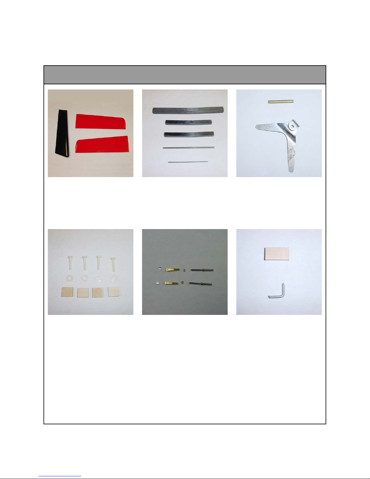
Wing Bolts
1. 5/16” Nylon Bolt (4)
2. 5/16” Nylon Washer (4)
3. Wood Retainer Block (4)
Elevator Bag
1. 3/16” Elevator Pivot Tube
2. Elevator Bellcrank
Joiners
1. Main Wing Joiner
2. Outer Wing Joiner (2)
3. 5/32 Stabilizer Joiner
4. 3/32 Stabilizer Joiner
Parts List
Tail Group
1. Rudder
2. Left Stabilizer
3. Right Stabilizer
Towhook Hardware
1. Towhook
2. Mounting Block
Page 4
Super XC
Elevator Pushrod Hardware
1. 4-40 Rod Ends (2)
2. 4-40 Jam Nuts (2)
3. 4-40 Clevis and Lock (2)

Flap Hardware
1. Flap Linkages (2)
2. Control Horns (2)
Rudder Hardware
1. Pull-Pull Kevlar
2. 2-56 Threaded Rod (4)
3. 2-56 Jam Nuts (4)
4. 2-56 Clevis and Lock (4)
5. Control Horns (2)
Parts List
Rudder Hinges
1. Hinges (3)
2. Pockets (3)
Page 5
Super XC
Aileron Hardware
1. Aileron Linkages (2)
2. Ball Links (2)
Table of contents
Popular Toy manuals by other brands

FUTABA
FUTABA GY470 instruction manual

LEGO
LEGO 41116 manual

Fisher-Price
Fisher-Price ColorMe Flowerz Bouquet Maker P9692 instruction sheet

Little Tikes
Little Tikes LITTLE HANDIWORKER 0920 Assembly instructions

Eduard
Eduard EF-2000 Two-seater exterior Assembly instructions

USA Trains
USA Trains EXTENDED VISION CABOOSE instructions


