DG Technologies VSI-2534 User manual

Page | 2
This document describes DG Technologies VSI-2534. The VSI-2534 is an SAE J2534 Pass-Thru
device with its primary purpose to program automotive ECUs (Electronic Control Units).
The VSI-2534 is also useful for vehicle diagnostics, development, general design, hardware-in-
the-loop simulation and anywhere communications with a vehicle network are required.
Permission is granted to copy any or all portions of this manual, provided that such copies are for use with the VSI-
2534 product and that “© 2019 DG Technologies.”, (herein referred to as “Dearborn Group”, “DG Technologies”,
or “DG”), remains on all copies.
The accompanying software, provided for use with the VSI-2534, is also copyrighted. Permission is granted to copy
this software for back-up purposes only.
I M P O R T A N T
To ensure your success with this product, it is essential that you read this document carefully before using the
hardware.
Damage caused by misuse of the hardware is not covered under product warranty. When using this manual, please
remember the following:
❑ This manual may be changed, in whole or in part, without notice.
❑ DG assumes no responsibility for any damage resulting from the use of this hardware and software.
❑ Specifications presented herein are provided for illustration purposes only and may not accurately
represent the latest revisions of hardware, software or cabling.
❑ No license is granted, by implication or otherwise, for any patents or other rights of DG or of any third
party.
DG® logo is a registered trademark of DG Technologies, Inc. Other products that may be referenced in this manual
are trademarks of their respective manufacturers.
© 2006 - 2019 DG Technologies, Inc.

Page | 3
Contents
1. Introduction ......................................................................................5
1.1 VSI-2534 hardware specifications .......................................................................................6
1.2 Power Connector .....................................................................................................................6
1.2.1 Powering up the hardware.............................................................................................6
1.2.2 Vehicle network connection..........................................................................................6
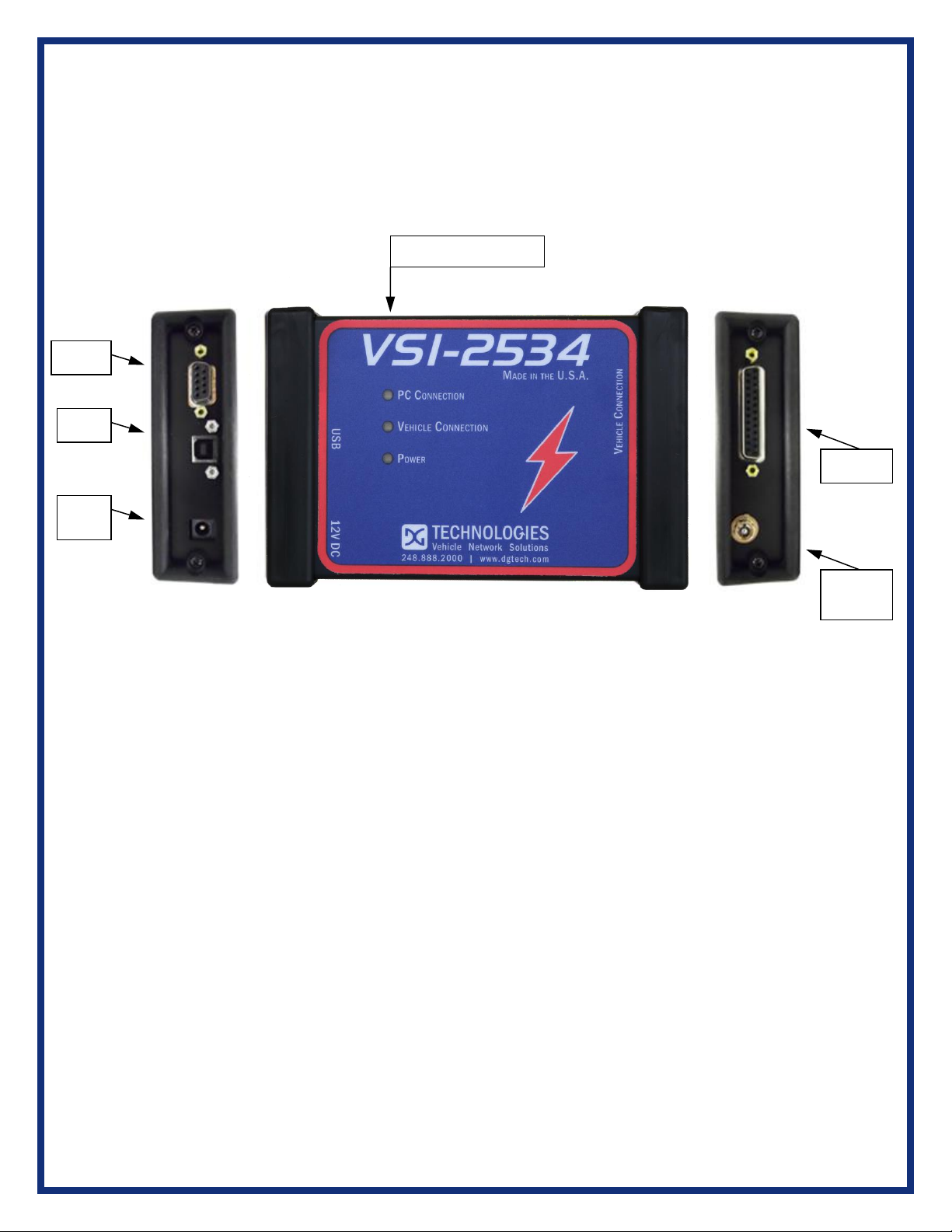
1.3Hardware overview..................................................................................................................7
1.3.1 Toggle Switch....................................................................................................................7
1.3.2 DB-25...................................................................................................................................7
1.3.3 DB-9.....................................................................................................................................7
1.3.4 USB......................................................................................................................................7
1.3.5 12V DC.................................................................................................................................7
1.3.6 Status Indicators..............................................................................................................8
1.3.7 Status Indicators Table...................................................................................................8
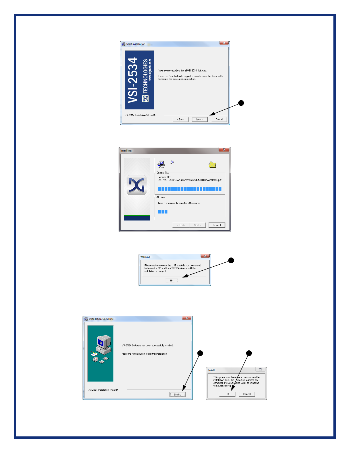
2. Software Setup .................................................................................9
3. Hardware Configuration.................................................................11
3.1 First Time Hardware Connection to the PC.....................................................................11
3.2 Typical Hardware Connection to the PC...............................................................................12
3.3 Hardware Configuration Information .....................................................................................13
4. Software ..............................................................................................14
4.1 VSI-2534 Validation Utility.........................................................................................................14
4.2 DG Assist.......................................................................................................................................14
4.3 DG Diagnostics OBDII................................................................................................................14
4.4 Data Link Monitor 2 (DLM2)......................................................................................................14
4.5 Software Development Kit (SDK)............................................................................................14
4.6 DG Updater....................................................................................................................................14
4.6.1 DG Driver Update –Internet Connection Required.....................................................14
4.6.2 DG Driver Update –Initial Screen....................................................................................15
4.6.3. DG Driver Update –Main Update Screen......................................................................15
4.6.4 Successful Connect –Updates Available......................................................................16
4.6.5 Advanced Settings –Setting Default Time for Check for Updates.........................17

Page | 4
4.7 Hardware/Firmware Update of the VSI-2534 ........................................................................18
5. Technical Support and Return Merchandise Authorization (RMA) .19
5.1. Technical Support......................................................................................................................19
5.2. Return Merchandise Authorization (RMA)...........................................................................19
6. Warranty Information and Limitation Statements ............................20
6.1. Warranty Information ................................................................................................................20
6.2. Limitation Statements...............................................................................................................20
6.2.1. General Limitation and Risk Assignment.....................................................................20
6.2.2. Exclusion of Incidental, Consequential and Certain Other Damages...................20
6.2.3. Limitation of Liability and Remedies.............................................................................21
6.2.4. Right to Revise or Update without Notice....................................................................21
6.2.5. Governance..........................................................................................................................21
6.2.6. Contact...................................................................................................................................21
7. Troubleshooting.............................................................................21
7.1 VSI-2534 Validation Utility.........................................................................................................21
7.2 Windows “Side-by-Side” Error ................................................................................................21
7.3 OEM Application Troubleshooting .........................................................................................21
Appendix A –Pin Assignment for the OBD II Cable.............................22
Appendix B –List of Acronyms Used in this Document......................23

Page | 5
1. Introduction
How it works: A PC is connected to a vehicle through the VSI-2534 “Pass-Thru device” to the
OBD-II J1962 connector and on to the ECUs. The VSI-2534 provides the translation interface
between the PC and the vehicle or module.
The user software application on the PC sends and receives data to the vehicle using the DG
Technologies VSI-2534.
Provides support for: the most current version of the J2534 API (Version 04.04) and D-PDU
API.
Supports the following protocols:
CAN (ISO 11898, J2284)
Single-Wire CAN
ISO15765
ISO 9141
KWP2000
J1850 PWM (Ford SCP)
J1850 VPWM (both GM Class 2 and Chrysler)
SCI
GM-UART
Features:
•USB 2.0 connection to a PC for fast downloads. (Operates at full network speed with fast
and efficient data transfers.)
•Connects to a vehicle with an OBDII cable or a custom cable.
•Runs the SAE J1699 Vehicle Validation software.
•On or off-board J2534 module programming.
•Programming voltages –5 to 20 V in 100 mV steps.
•Useful for diagnostics or module development.

Page | 6
1.1 VSI-2534 hardware specifications
Dimensional
Height: 4.375 in
Width: 6.625 in.
Depth: 1.312 in.
Weight
VSI-2534 tool: 13.3 oz.
OBD II cable: 10.9 oz.
Electrical
Nominal Voltage: 12 VDC
Maximum Voltage: 27 VDC
Current consumption: Less than 200 mA at 12 VDC
Temperature range: - 40 C to +85 C
1.2 Power Connector
The VSI-2534 can be powered via either a power jack (12V DC) OR via the supplied OBD II
cable attached to the vehicle. (See 1.3.1 for more information on 12V DC usage)
WARNING: The VSI-2534 SHOULD NOT be powered via the power jack AND the supplied
OBD II cable SIMULTANEOUSLY. Connecting to multiple power sources may cause
damage to the hardware.
1.2.1 Powering up the hardware
Once a power source has been connected, the POWER LED should light green. See
Section 1.3.2 fordetails.
1.2.2 Vehicle network connection
The vehicle network connection can be made by using the supplied OBD II cable or
by a custom cable to the hardware’s DB-25 (female) connector, see Appendix A.

Page | 7
1.3 Hardware overview
The following figures show the external features of the VSI-2534:
Figure 1: VSI-2534 Front & Side Views
1.3.1 Toggle Switch
The Toggle Switch can be used to simulate the vehicle ignition switch (on/off)
when the VSI-2534 is powered via a 12V DC input. An example of this scenario
would be reflashing on the bench. When powered via. the supplied OBDII cable,
the Toggle Switch is not active.
1.3.2 DB-25
This is the connector where the OBDII cable connects and powers the VSI-2534
from the vehicle connection.
1.3.3 DB-9
This is no longer in use.
1.3.4 USB
This is where the USB cable connects to the device to the PC.
1.3.5 12V DC
This is the external Power Connector.
Toggle
Switch
DB-25
DB-9
Status (3) Indicators
USB
12V
DC

Page | 8
1.3.6 Status Indicators
The VSI-2534 has three status LEDs that indicate activity of the following functions:
▪PC Connection –Indicates that the VSI-2534 has established a connection
to the PC, and if the link is “active.”
▪Vehicle Connection –Indicates that the vehicle network connection is
established / active.
▪Power –Indicates that the VSI-2534 is connected to a power supply (either
via the jack plug or through a vehicle connection), and whether or not the unit
is operating properly.
1.3.7 Status Indicators Table
LED Name
LED State
Description
PC Connection
Off
PC has not initialized communication with
VSI-2534 via the USB data link.
On
(Solid Red)
PC has initialized communication with VSI-
2534 via the USB data link. No bus activity.
On
(Alternating Red / Green)
Activity on the PC-VSI-2534 connection via
USB data link.
Vehicle
Connection
Off
No vehicle network protocol channel has
been initialized for use.
On
(Red)
One or more vehicle network protocol
channels have been initialized for use. No
bus activity.
On
(Alternating Red / Green)
There is activity on one or more vehicle
network protocol channels.
Power
Off
No power supplied to the VSI-2534 unit.
On
(Solid Green)
Unit is powered either via the vehicle
connector or the external power jack. Unit is
operating properly.
On
(Solid Red)
Unit is powered either via the vehicle
connector or the external power jack. Unit is
not operating properly.
Table 1: LED Descriptions

Page | 9
2. Software Setup
1. If it does not start automatically, locate the “Setup_VSI2534.EXE” file on the CD
and double-click on it to start the software setup, and then click “Next”.
2. Exit all open Windows programs and click “Next” to continue.
3. Choose Destination Location for the installation. The default location is
C:\Dearborn Group Products\VSI-2534. Click “Next” to continue.

Page | 10
4. Click “Next” to continue.
5. Installing…
6. Ensure that you do not have the VSI-2534 hardware connected to the PC’s USB
port. Click “OK” to continue.
7. Installation is complete. Click “Finish”, then click “OK” to reboot the PC.

Page | 11
3. Hardware Configuration
3.1 First Time Hardware Connection to the PC
Note: For Windows Vista or 7 32-bit ONLY, see below. For Windows Vista or 7, 64-bit, a screen
will display in the lower right corner of the screen indicating automatic driver installation.
Step 1: Connect the VSI-2534 to a power source (Power adapter or powered from the
OBD II cable). Note: do not power unit from multiple sources. Power LED must be a
solid Green. Connect USB Cable to PC. In some versions of Windows the final step in
driver installation is automatic. In others, the Windows Found New Hardware Wizard will
run to finalize driver installation. This can take a few moments to come up.
Step2: Select “Install the software automatically” or “Yes now – and every time I
connect a new device” and click “Next”.
Step3: Click “Finish”.

Page | 12
3.2 Typical Hardware Connection to the PC
Step 1: Connect the VSI-2534 to a power source (12V Power adapter or powered from
the OBD II cable). Note: Do not power unit from multiple sources. Power LED must be a
solid GREEN.
Step 2: Connect the VSI-2534’s USB cable to the PC that the software was installed on
and note that the Power LED is a solid Green and the PC Connection LED is a solid
RED.
Step 3: Connect the OBDII cable provided to the vehicle or using an application such as
the DG 2534 SDK (Software Development Kit), shown above, a user can open a link to
the hardware and connect with a protocol to a Vehicle or an Electronic Control Module
(ECU). Note: after this connection, the Vehicle Connection LED is a solid RED.

Page | 13
3.3 Hardware Configuration Information
By running the “VSI-2534 Config Utility”, located in Start > All Programs > DGTech VSI-
2534, a user can find out Hardware version, protocol support, and other information.
The “Get Firmware Version” button provides the Firmware version of the VSI-2534
hardware. Note: Do not have any other application running that uses the J2534 library.
The “Turn Logging ON” checkbox enables the Configuration button. The Configuration
button enables the user to set “Logging Type” and “Logging Method” to create VSI-2534
DLL log. Note: Do not have any other application running that uses the J2534 library.
Protocols Supported: J1850VPW, J1850PWM, CAN, ISO9141, ISO14230, ISO15765,
SCI_A_ENGINE:1, SCI_A_TRANS:1, SCI_B_ENGINE:1, SCI_B_TRANS:1,
SWCAN_ISO15765_PS, SWCAN_PS, GM_UART_PS
J2534 API Version: 04.04

Page | 14
4. Software
4.1 VSI-2534 Validation Utility
Please refer to the “DG VSI-2534 Validation Utility User Guide” found in:
Start>Programs>Dearborn Group Products>VSI-2534>Documentation.
4.2 DG Assist
Please refer to the “DG Assist User Manual” found in: Start>Programs>Dearborn
Group Products>DG Assist.
4.3 DG Diagnostics OBDII
Please refer to the DG Diagnostics OBDII User Guide found in:
Start>Programs>Dearborn Group Products>VSI-2534>Documentation.
4.4 Data Link Monitor 2 (DLM2)
Please refer to the “DLM2 Manual” found in: Start>Programs>Dearborn Group
Products>DLM2.
4.5 Software Development Kit (SDK)
Please refer to the “DG J2534 SDK Manual” found in: Start>Programs>Dearborn
Group Products>VSI-2534>Documentation.
4.6 DG Updater
DG Update is an application that is installed with your VSI drivers. It will run (by
default) once every 30 days, and will keep you up-to-date with the latest versions
of drivers for all your DPA, DG Diagnostics, and VSI-2534 products. With this
application running regularly and Automatic Firmware Update (see DPA user
manual) turned on, this will keep your DPAs up-to-date with drivers and firmware.
DG recommends our customers keep up-to-date so that your OEM and
component manufacturer diagnostic applications run smoothly.
The utility will run once every 30 days as a user logs on. This value is
configurable, but defaults to 30 days. It can also be invoked manually from the
Windows Start Menu:
Start > Programs > Dearborn Group Products > VSI-2534 > DG Update
4.6.1 DG Driver Update –Internet Connection Required
The DG Driver Update utility depends on successfully connecting to the
Internet (to one of DG’s servers) to retrieve the latest version information
and to download the latest drivers and applications if necessary.
Many companies install firewalls and virus protection and these may block
the DG server queries and responses. If you are connected to the Internet
and have issues running DG Update (getting “Unable to connect to the

Page | 15
internet to check for updates." messages), ensure that your firewall or
virus protection will allow a connection to the following Internet host/site
and port: fh.dgtech.com, port 8888. There are too many firewall and
virus programs on the market to cover in this manual, however if you
contact your network administrator and give him the host and port number,
he should be able to configure your PC to allow the communication. You
may also consult the Windows help system and/or the documentation for
your firewall and/or virus protection software.
4.6.2 DG Driver Update –Initial Screen
When the utility runs as a user logs on, the following screen will appear in
the lower right hand corner of the screen. If you want to check for updates,
ensure that your PC is connected to the Internet and click Continue.
Clicking Cancel will cause DG Update to wait until the next time it is
scheduled to run. Clicking Continue will bring up the main update screen.
4.6.3. DG Driver Update –Main Update Screen
The main screen appears looking like this. Depending on which products
are installed on your PC, the grid will display pertinent information about
them. When selecting DG Update from the Windows Start Menu, this is
the first screen to appear.

Page | 16
Connect your PC to the Internet and click the Check for Updates button.
Due to the nature of TCP/IP communications, errors connecting or
sending/receiving of data are slow to appear, however the user will
eventually be notified if there was a problem.
If the check for updates was successful, the second column of the grid will
display information returned from the DG server showing the most current
versions and the Install Status row will change to red, green or blue.
Color
Description
Green
Drivers up-to-date. No update necessary.
Red
Drivers are outdated. Update recommended.
Blue
Drivers on your PC are newer than current version.
This usually indicates you are running a beta copy of the DPA drivers.
4.6.4 Successful Connect –Updates Available
Out of date message box
Progress bar and Download button shown
In this case, the VSI-2534 drivers are out of date (red), the user will be presented with a
prompt notifying them that there are updates available. Only if updates are available will
the Download button and progress bar show up on the screen. The progress bar will
keep you informed of the download progress should you choose to download the latest
drivers by clicking the Download button.

Page | 17
When you click the Download button, you will be prompted to confirm starting of the
download.
Prompt asking if drivers should be downloaded
Note: The DG Update application can only download and install one item at a time. The
user will be prompted for whichever one they want to update first.
After choosing Yes, the program will download the drivers and update the progress bar
while doing so. Once the drivers have been downloaded, the application will unzip them
and start the installation process. The dialog box will go away after the install has been
started.
Do not disconnect your VSI or shut down your computer until installation is complete
After the drivers have been downloaded (to the Windows temp directory –if you wish to
save them for other machines), they will be unzipped and the program will exit right after
starting the new driver installation. Follow the installation instructions in the appropriate
User Manual.
4.6.5 Advanced Settings –Setting Default Time for Check for Updates
If you want to turn off, or alter the timeout period where the user is prompted to check for
updates (the dialog below), press the Settings button. The advanced settings dialog box will
be displayed. To turn off the checking prompt, set the value to 0 (zero). Otherwise, you can
set the number of days between checks.
Small dialog box that appears In the system tray
Advanced settings screen

Page | 18
4.7 Hardware/Firmware Update of the VSI-2534
.
Step 1: Go to: Start>All Programs>DGTech VSI-2534>FirmwareUpdater.
*NOTE: Adaptor must be plugged in
Select the drop-down menu for “Adapter” and select “VSI-2534 USB”.
Step 2: Click on “Yes”.
Step 3: Updating the Firmware...
Step 4: Firmware has been updated. Click “OK”

Page | 19
5. Technical Support and Return Merchandise Authorization
(RMA)
5.1. Technical Support
After reading and following the troubleshooting and validation procedures and
still not being able to resolve an issue, please feel free to contact DG technical
support. For users in the United States, technical support is available from 9 a.m.
to 5 p.m. Eastern Time. You may also fax or e-mail your questions to us. For
prompt assistance, please include your voice telephone number.
DG Technologies Technical Support
Phone: (248) 888-2000
Fax: (248) 888-9977
E-mail: [email protected]
Web site: www.dgtech.com
Users not residing in the United States should contact your local DG representative or e-mail
techsupp@dgtech.com
5.2. Return Merchandise Authorization (RMA)
If technical support has deemed that there may be a physical problem with your
VSI, you will be issued you an RMA number. You would then return the product
along with any documentation of ownership you have (proof of purchase/price) to
the following address:
Product Service/Repairs
Attn: RMA# xxxxxxx
DG Technologies
33604 West 8 Mile Road
Farmington Hills, MI 48335

Page | 20
6. Warranty Information and Limitation Statements
6.1. Warranty Information
DG Technologies VSI-2534 is warranted against defects in materials and workmanship for two (2) years following date of
shipment. Cables (both USB and vehicle) are warranted for 90 days.
DG Technologies, Inc. will, at its option, repair or replace, at no cost to the customer, products which prove to be defective
during the warranty period, provided the defect or failure is not due to misuse, abuse, or alteration of the product. The
customer is responsible for shipment of the defective product to DG. This warranty does not cover damage to any item
that DG Technologies determines has been damaged by the customer's abuse, misuse, negligence, improper assembly,
modification, or operation of the product.
A Return Merchandise Authorization (RMA) number must be issued to the customer by our Technical Support Department
at (248) 888-2000 and must be included with the product being returned (for more details, see section Return
Merchandise Authorization (RMA)). A VSI is warranted for 90 days after a warranty repair, or to end of the original factory
warranty period, whichever is longer.
6.2. Limitation Statements
6.2.1. General Limitation and Risk Assignment
To the maximum extent permitted by applicable law, DG Technologies
and its suppliers provide support services on an “as-is” basis and disclaim
all other warranties and conditions not specifically stated herein, whether
express, implied or statutory, including, but not limited to, any warranties
of merchantability or fitness for a particular purpose, lack of viruses,
accuracy or completeness of responses, results, lack of negligence or lack
of workmanlike effort, and correspondence to description. The user
assumes the entire risk arising out of the use or performance of the
device, its operating system components, and any support services.
6.2.2. Exclusion of Incidental, Consequential and Certain Other
Damages
To the maximum extent permitted by applicable law, in no event shall DG
Technologies or its suppliers be liable for any special, incidental, indirect
or consequential damages whatsoever, including but not limited to:
damages for loss of profit, loss of confidential or other information;
business interruption; personal injury; loss of privacy, failure to meet any
duty (including good faith or of reasonable care); negligence; and any
other pecuniary or other loss related to the use of or the inability to use the
device, components or support services or the provision of or failure to
provide support services or otherwise in connection with any provision,
even if DG Technologies or any supplier has been advised of the
possibility of such damages.
Table of contents
Popular Scanner manuals by other brands

Canon
Canon CanoScan N340P Service bulletin

Kodak
Kodak Scanmate i1120 user guide

Golden engineering
Golden engineering XR150 Operator's manual

Canon
Canon DR 5010C - imageFORMULA - Document Scanner Specifications

Avision
Avision FL1503B user manual

Canon
Canon imageFORMULA P-150 Portable Scanner reference guide