DHA Four-channel DC Controller DMX Instructions for use

LIGHTING LIMITED
Four-channel
DC Controller DMX
Instruction &Maintenance
Manual

Contents
1 Four-channel DC Controller DMX 3
Front Panel Controls
Dmx Operation
2 Rotation Direction 4
3 Status LED 5
Load Compensation
4 Rear Panel Connections 6
and iring
5 Cross Over Splitter 7
6 Four Channel System 8
7 Power Output Protection 9
8 Fuse Replacement 10
Mains Voltage Selection
9 Declaration of Conformity 11
Four Channel DC Controller DMX
1
The DHA Lighting DC Controller DMX supplies power for up to four
Varispeed moving effects units. Speed and direction of the effects are
remotely controlled via a DMX512 input port or can be preset from the
front-panel controls.
he controller can drive one Varispeed effect per channel. ypical speeds
obtained are 0—20rpm for Gobo Rotators (0—10rpm for the Double Gobo
Rotator) and 0—5rpm for Yoyos and Animation units.
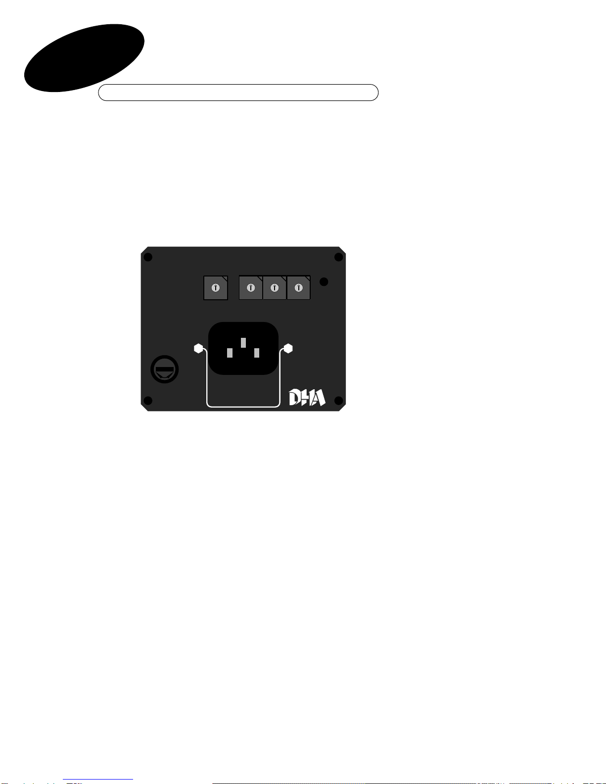
Front Panel Controls
he front panel controls comprise four rotary switches, each marked 0—9,
and a status indicator LED. Also on the front panel are an IEC mains input
socket and fuse. he mains supply voltage (non-dim) is selectable
internally. he set voltage is marked on the base of the unit.
DDMMXX OOppeerraattiioonn
With switch 1 (far left) in position 0, the DC controller DMX can be remotely
controlled from a lighting console, or similar device, capable of producing a
DMX512 signal. Switches 2, 3 & 4 are used to set the DMX address. Eight
consecutive DMX channels are required.
3
DC CONTROLLER DMX
CH 1 CH 3
DMX ADDRESS
FUSE
100 mA
MANUAL CONTROL
DMX CONTROL CH1 = 0
CH 2 CH 4
F
U
S
E
5
1
0
2
3
4
6
7
8
9
5
1
0
2
3
4
6
7
8
9
5
1
0
2
3
4
6
7
8
9
5
1
0
2
3
4
6
7
8
9

Rotation Direction
wo DMX channels are used to control each DC controller channel – one for
forward speed and one for reverse. he speed and direction of the DC
controller output are derived from the difference between the levels of
these two signals (see example in Fig.1). Effect speed is continuously
variable from zero to maximum in either direction. he response has been
tailored to give greater control at the lower end of the speed range.
Where more than one effect unit is used, the direction of motor rotation will
remain consistent between units. However, the apparent direction of the
on-stage lighting effect is dependent on the focus of the individual effect
and on the viewpoint of the observer.
MMaannuuaall OOppeerraattiioonn
Where switch 1 is set to any value other than zero, the outputs of the effect
channels 1 to 4 are directly controlled by switches 1 to 4 respectively and
any DMX signal is ineffective.
he speed of each effect is variable in discreet increments from zero to nine
ranging from stationary to maximum speed for the effect. here is no
control over direction in this operating mode and all effects will move in the
nominal ‘forward’ direction.
2
4
Lighting Console
Channels
DC Controller
Channels
1 2 3 4 5 6 7 8
CHANNEL 1
Full Speed Forward
CHANNEL 2
Stationery
CHANNEL 3
Stationery
CHANNEL 4
Slow Speed Forward
Fig 1

Status LED
DDMMXX MMooddee ((SSwwiittcchh 11 == 00))
When the unit is operating correctly the status LED will be on continuously
except for a blink every 2.5 seconds. If the device detects any faults or
error conditions the LED changes to a flashing pattern consisting of two
flashes then a pause. Each flash corresponds to a particular type of error
and will be a long flash if that error has occurred or a short flash if it has
not.
If the DC Controller DMX is not receiving all eight channels of DMX, error 1
will be signalled and the device will not function in DMX mode.
The DC Controller DMX requires eight consecutive channels of DMX to
operate, eg.
Unit 1 Forward DMX Address
Unit 1 Reverse Address + 1
Unit 2 Forward Address + 2
Unit 2 Forward Address + 2 etc until
Unit 4 Forward Address +6
Unit 4 Forward Address +7
Manual Mode (Switch 1 ≠ 0)
he LED is off except for a short flash every 2.5 seconds. No program
detectable errors are possible in this mode.
SSttaattuuss LLEEDD CCooddeess
Flash Error Explanation
1 No DMX Data No DMX has been received for over a second.
2 DMX Data Error Bad data on DMX line (framing error).
– resets automatically 10 seconds after
last occurrence.
LLooaadd CCoommppeennssaattiioonn
Each channel of the DC controller has automatic, load-compensation
circuitry. When operating at slow speeds, the mechanical load on the
motor being driven is monitored, and compensated when necessary, by an
automatic increase in output voltage to maintain constant speed. his
occurs for heavy or uneven loads (eg. the Yoyo effect which has greater
resistance during its upward travel).
3
5
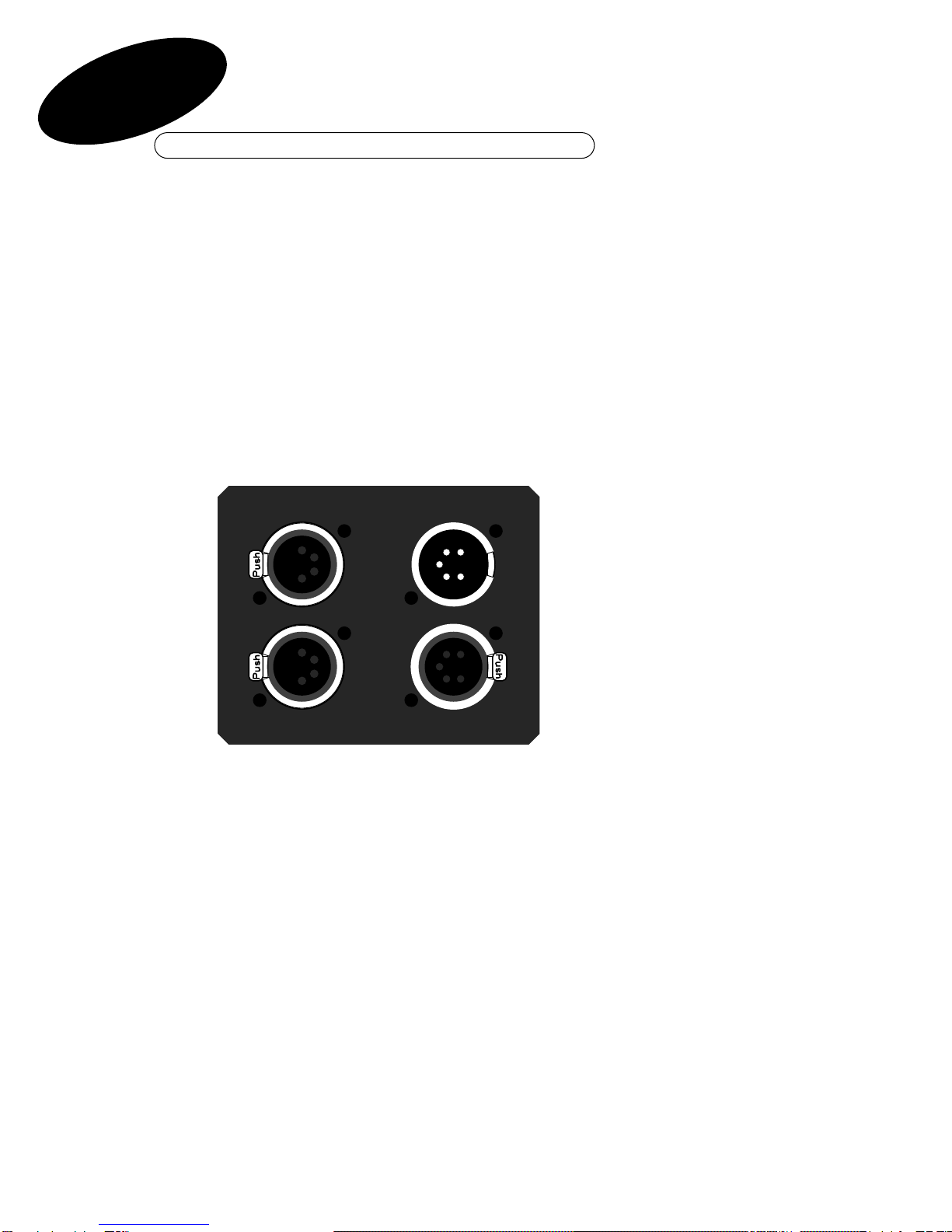
Rear Panel Connections
he rear panel of the DMX to Light alk convertor carries four XLR-type
connectors. o the right are two DMX standard XLR-5 connectors – male for
DMX input and female for DMX output. hese two are simply connected
through internally so the DMX cabling can be daisy chained from device to
device in the normal way. he unit contains no termination and an external
DMX terminator must be fitted if this is the last device in the DMX chain.
Motor drive output from the unit is via the two XLR 4-pin female connectors
to the left. Each connector carries two channels. he lower connector
feeds the drive for channel 1 on pins 1&2 and for channel 2 on pins 3&4.
Similarly, the upper connector feeds the drive for channel 3 on pins 1&2
and for channel 4 on pins 3&4.
Due to the operation of the load-compensation circuitry, nnoo mmoorree tthhaann oonnee
eeffffeecctt uunniitt mmuusstt bbee ppoowweerreedd ffrroomm eeaacchh cchhaannnneell.
When making up cabling note that DHA Varispeed Moving Effects are
supplied fitted with XLR 4-pin male connectors. With older effects, the
motor will operate on channel 1 or 3 (pins 1&2); more recent equipment
has a switch to select between channels.
4
6
CH 1 - 2
CH 3 - 4 DMX IN
DMX OUT
5
1
23
4
123
4123
4
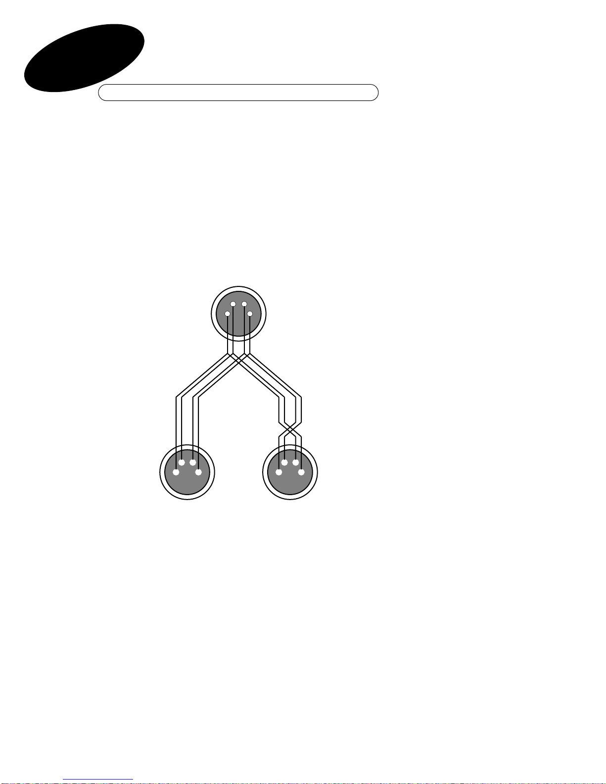
Cross–Over Splitter
7
Fig 2
4– pin XLR male
4– pin XLR female
o connect effects to all four channels it is necessary to use 2-way
crossover splitters – hese should be wired as shown in fig.2.
External cables should be 0.75mm cross section (18 AWG) to minimise
voltage loss, particularly over long runs.
DHA can supply extension cables and 2-way crossover splitters which
combine to greatly simplify wiring runs to remote locations. An example is
shown in fig.3.

Four Channel System
Fig 3
6
Channel 1 Channel 2
Channel 3
Channel 4
Controller
8

Power Output Protection
9
he motor drive outputs are protected by a self-resetting thermal cutout.
his provides protection against short circuits and also protects motors
from burnout due to stalling by external force or overloading.
When a short circuit or overload occurs on an output channel the output on
all channels will be greatly reduced and the main (red) power LED will be
dimmed significantly. After a few seconds the thermal cutout will be
activated on the short-circuit channel and the remaining channels will
return to normal operation. he cut-out time will vary depending on the
output settings of the controller but, provided that external wiring
conforms to the standard recommended by DHA Lighting, there will be no
immediate damage to either the DC controller or any DHA moving effects
connected.
While the fault persists the affected channel will remain in shutdown. he
controller should not be left in this state for any prolonged period.
he DC controller should recover in a matter of seconds once the source of
the fault is removed.
7

Fuse Replacement
Mains input is selectable internally between 100—120V AC or 220—240V
AC and is protected by a fuse, accessible from the front panel.
oo rreeppllaaccee tthhee mmaaiinnss ffuussee::
• Press and turn the cap of the fuse holder anticlockwise to release
the lock and withdraw the cap which holds the fuse itself. Replace the fuse
and lock the cap back into the fuse holder (press and turn clockwise). Use
only 100mA, 20mm x 5mm, fast-blow HRC fuses.
oo cchhaannggee tthhee mmaaiinnss vvoollttaaggee sseettttiinngg::
• Disconnect from mains supply before opening case!
• Undo the four retaining screws on the front panel, and gently pull
the panel away from the body until the voltage selector switch is visible on
the lower printed circuit board.
• For 100-120 V supply set switch to position 2 (left).
• For 220-240 V supply set switch to position 1 (right).
• Carefully replace the front panel and secure with the original
screws.
Reference
he DMX512 Digital Data ransmission Standard for Controllers and
Dimmers
United States Institute of heater echnology, July 1986.
Operation of the unit on 220-240V supplies when set for 110V operation
will damage the controller and may also damage any Moving Effects units
connected. Operation at 110V when set for 220V will not cause damage but
the full range of speeds will not be available.
10
8

Declaration of Conformity
9
DMX DC CONTROLLERProduct Name: DCONDMXModel Number(s):
115V or 230V 50/60Hz ACProduct Options:
EN50081-1 Emissions
EN50082-1 Immunity
EN61000-3-2 Harmonics
EMC:
The products herewith comply with the requirements of the Low
Voltage Directive 73/23/EEC and the EMC Directive 89/336/EEC. The
products were tested in a typical configuration.
Supplementary Information:
Manufacturer's Name DHA Lighting Limited.
Manufacturer's Address
DHA Lighting Limited
284 - 302 Waterloo Road
London SEI 8RQ
England
declares, that the product(s):
conform(s) to the following Product Specifications:
European Contact:
DHA Lighting Limited
284 - 302 Waterloo Road London SEI 8RQ England
Tel +44 (0)171 771 2900 Fax +44 (0)171 771 2901
David K Hersey
Director
ISO/IEC Guide 22 and EN 45014According to
DECLARATION OF CONFORMITY
Date
Relevant clauses of
EN 60-065: 1993
Safety:
30/8/96
11

284 – 302 WA ERLOO ROAD LONDON SE1 8RQ tel +44(0)20 7771 2900 fax +44 (0)20 7771 2901
Table of contents
Popular Lighting Equipment manuals by other brands

National Specialty Lighting
National Specialty Lighting LED Brick Star Gen I installation instructions

Emergi-Lite
Emergi-Lite Lux-Ray LED manual

mbt Lighting
mbt Lighting LZ600RG user manual

Luxli
Luxli TIMPANI2 user manual

Prilux
Prilux flexilight MAXIBRILLO manual

Larson Electronics
Larson Electronics EPL-HB-150LED-RT-100-EPP instruction manual


Patlite
Patlite LR4 Complete Operation Manual

Acclaim Lighting
Acclaim Lighting Flex Tube SC G2 user guide

ALPHA LITE
ALPHA LITE E Series User manual book

Current
Current GEPS24-180U installation guide

LIVARNO home
LIVARNO home HG07137A Assembly, operating and safety instructions

Defiant
Defiant 84045 Use and care guide