DHC BT1000 HD User manual

1
Model BT1000 HD
BATTERY & ELECTRICAL SYSTEM ANALYZER
OWNER’S MANUAL
READ ENTIRE MANUAL BEFORE USING THIS PRODUCT
BATTERY/CHARGING/STARTING SYSTEM ANALYZER / PRINTER
1
English

2
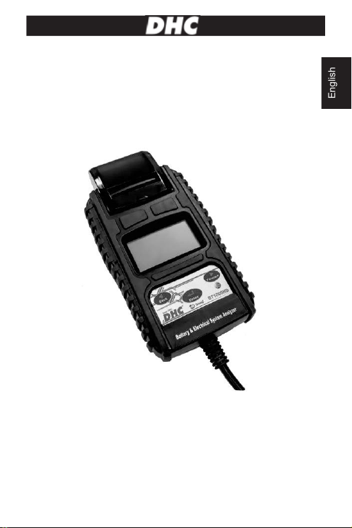
TEST PROCEDURES / OPERATING INSTRUCTIONS
IMPORTANT
1. For testing 6 and 12 volt batteries, 24V battery pack, and for testing 12 and 24
volt charging systems.
2. Suggested operation range 0濎(32ʲ) to 50濎(122ʲ) in ambient
temperature.
WARNING
WARNING: This product can expose you to chemicals including arsenic, which is
known to the State of California to cause cancer.
For more information, go to www.P65Warnings.ca.gov.
1. Working in the vicinity of a lead acid battery is dangerous. Batteries generate
explosive gases during normal battery operation. For this reason, it is of
utmost importance, if you have any doubt, that each time before using your
tester, you read these instructions very carefully.
2. To reduce risk of battery explosion, follow these instructions and those
published by the battery manufacturer and manufacturer of any equipment
you intend to use in the vicinity of the battery. Observe cautionary markings on
these items.
3. Do not expose the tester to rain or snow.
PERSONAL SAFETY PRECAUTIONS:
1. Someone should be within range of your voice or close enough to come to
your aid when you work near a lead acid battery.
2. Have plenty of fresh water and soap nearby in case battery acid contacts skin,
clothing or eyes.
3. Wear safety glasses and protective clothing.
4. If battery acid contacts skin or clothing, wash immediately with soap and water.
If acid enters eye, immediately flood eye with running cold water for at least
ten minutes and get medical attention immediately.
5. NEVER smoke or allow a spark or flame in vicinity of battery or engine.
2
English

3
6. Be extra cautious to reduce risk of dropping a metal tool onto the battery. It
could spark or short-circuit the battery or other electrical parts and could cause
an explosion.
7. Remove personal metal items such as rings, bracelets, necklaces and
watches when working with a lead acid battery. It can produce a short circuit
current high enough to weld a ring or the like to metal causing a severe burn.
PREPARING TO TEST:
1. Be sure area around battery is well ventilated while battery is being tested.
2. Clean battery terminals. Be careful to keep corrosion from coming in contact
with eyes.
3. Inspect the battery for cracked or broken case or cover. If battery is damaged,
do not use tester.
4. If the battery is not sealed maintenance free, add distilled water in each cell
until battery acid reaches level specified by the manufacturer. This helps
purge excessive gas from cells. Do not overfill.
5. If necessary to remove battery from vehicle to test, always remove ground
terminal from battery first. Make sure all accessories in the vehicle are off to
ensure you do not cause any arcing.
OPERATION & USE:
Note: Each time you connect the tester to a battery, the tester will run a quick
cable verification to ensure a proper connection through the output cables to
sensors in the clamp jaws. If the connection checks out OK, the tester will
proceed to the Home Screen. If the connection is poor, the display will show
“CHECK CABLE”. In this case, check cable connections for visible signs of
damage, as you may need to re-connect the clamps to the battery or replace the
cable end.
3
English

4
HOW TO REPLACE CABLE END:
1. Detach the clamp lead when the replacement is necessary.
2. Make sure the new clamp lead is well connected.
NOTE that do not detach the cables unless necessary to make sure
the pins are not rusted or corroded by the acid liquid.
BEFORE TESTING:
1. Before you test a battery in a vehicle, turn off the ignition, all accessories and
loads. Close all the vehicle doors and the trunk lid.
2. Make sure you have put 6 pcs 1.5V batteries into the battery chamber.
Oxyride batteries are not recommended because of the initial 1.7 Volt output.
If the 1.5V battery runs out of power, screen will show “POWER LOW”.
Replace those 6 pcs 1.5V batteries before starting the test.
Note that nothing will be seen on the display until the tester is
connected to a vehicle battery.
3. Make sure the battery terminals are clean. Wire brush them if necessary.
Clamp the black load lead to the vehicle negative battery terminal. Clamp the
red load lead to the vehicle positive battery terminal. Please clamp on the lead
part of the terminal only. Clamping on the iron part of the terminal will lead to
wrong test results.
4. Paper load:
Open the clear cover. Insert paper to the paper feeding for auto running the
paper into printer
4
English

5
PAPER REPLACEMENT:
A. Open the clear cover.
B. Insert replaced paper roll into the paper feeding for auto running the paper into
the printer.
C. Pull the paper slowly and straightly from the paper roll in the chamber.
MAIN MENU:
SYSTEM
ANALYZER
You will view the following screens by
pressing ◄/ ►to switch between all
functions and settings.
BATTERY TEST
XX.XX V
Press «ENTER» to do battery test.
SYSTEM TEST
XX.XX V
Press «ENTER» to do system test.
IN
-
VEHICLE TEST
XX.XX V
Press «ENTER» to do In-vehicle test.
PRINT
LAST
RESULT
Press «ENTER» to print last result.
LANGUAGE
SELECT
Press «ENTER» to change language.
5
English

6
TEST COUNTER
Press «ENTER» to see how many times you
tested in battery / system / in-vehicle test.
2018/02/05
13:25:00
Press «ENTER» to start Date & Time Setting.
Then press ◄/ ►to adjust “Year”. Press
«ENTER» to finish Year. Please follow
previous step to finish Month, Day, Hour &
Minute.
BRIGHTNESS
Press «ENTER» to start adjusting brightness
of the screen.
CUSTOMIZE
Press «ENTER» to edit customized info.
BATTERY TEST:
1.
Select BATTERY TEST. Press «ENTER».
BATTERY TEST
XX.XX V
2. Press the ◄►to select 6V / 12V battery or 24V Battery Pack.
6/ 12 V Batt. Test
2
4V Batt. Pcak Test
*When Selecting 24V battery pack test, the tester will ask the user to clamp 24V
battery pack (Using red clamp to connect positive terminal of battery 1, black
clamp to connect negative terminal of battery 2) before indivisually testing battery
1 & battery 2.
6
English

7
6 /12V Battery Test:
1. Press the ◄►to select REGULAR/STD or START/STOP battery.
REGULAR/STD
START/STOP
* REGULAR/STD BATTERY:
FLOODED, AGM FLAT PLATE, AGM SPIRAL, VRLA/GEL
* START/STOP BATTERY:
AGM FLAT PLATE, EFB
2.
Press the ◄►key to select the battery type:
BATTERY TYP
E:
AGM FLAT PLATE
3. Press «ENTER» to confirm choice.
4. Press the ◄►key to select the battery rating:
CCA/SAE, EN, JIS, DIN, IEC, & CA/MCA.
SELECT RATING:
CCA/SAE
5. Press «ENTER» to confirm choice.
6.
Press the ◄►key to input the battery
capacity.
CCA/SAE: 40~2000
EN: 40~1885
DIN: 25~1120
IEC: 30~1320
JIS: By Battery Type No.
CA/MCA: 50~2400
SELECT CAPACITY:
560CCA/SAE
7.
Press the ◄►key to confirm temperature.
ABOVE
32°F/0°C?
YES/
NO
7
English

8
8. Press <<Enter>> to begin the test.
*Return Feature: Before the test is started, the user can always return to
the previous setting page by pressing <<ENTER>> for 2 seconds.
SURFACE CHARGE NOTICE:
The battery will hold a surface charge if the engine has been running or after
the battery has been charged. The tester may prompt you to remove the
surface charge.
A. Follow the instructions indicating when to turn the headlights on and off or
apply a load into the battery.
IN VEHICLE:
SURFACE CHARGE
IN VEHICLE? YES
TURN HEADLIGHTS
ON FOR 15 SECS
OUT OF VEHICLE:
SURFACE CHARGE
IN VEHICLE? NO
TESTING
B. The tester will resume testing after it detects
that the surface charge is removed.
TESTING
9. Test the battery for few seconds.
10
.Press the ◄►key to select battery fully
charged or not if tester asks. Press «E
NTER» to
confirm choice.
IS BATTERY
CHARGED?
YES/NO
11. When the test is completed, the display shows the actual volts and the actual
CCA and internal resistance. {Press the ◄►key to read: SOH (STATE OF
HEALTH) and SOC (STATE OF CHARGE)}.
12.One of the six test results will be displayed:
GOOD & PASS
*The battery is good and capable of holding a
charge.
GOOD & PASS
VOL:
xx.xx V
CCA:
xxxx CCA/SAE
IR:
xx.xx mΩ
8
English

9
GOOD & RECHARGE
*The battery is good but needs to be recharged.
GOOD &
RECHARGE
VOL:
xx.xx V
CCA:
xxxx CCA/SAE
IR:
xx.xx mΩ
CAUTION
*The battery may be serviced but decrease the
capability of starting the engine gradually. The
battery may fail under extreme climate
conditions. There may be a poor connection
between the vehicle and the battery affect the
charging function. Please pay attention to the
battery for replacement consideration and
charging system checking.
CAUTION
VOL:
xx.xx V
CCA:
xxxx CCA/SAE
IR:
xx.xx mΩ
RECHARGE & RETEST
*Battery is discharged, the battery condition
cannot be d
etermined until it is fully charged.
Recharge & retest the battery.
RECHARGE &
RETEST
VOL:
xx.xx V
CCA:
xxxx CCA/SAE
IR:
xx.xx mΩ
BAD & REPLACE
*The battery will not hold a charge. It should be
replaced immediately.
BAD & REPLACE
VOL:
xx.xx V
CCA:
xxxx C
CA/SAE
IR:
xx.xx mΩ
BAD CELL & REPLACE
*The battery has at least one cell short circuit. It
should be replaced immediately.
BAD CELL &
REPLACE
VOL:
xx.xx V
CCA:
xxxx CCA/SAE
IR:
xx.xx mΩ
LOAD ERROR
*The tested battery is bigger than
2000CCA/SAE or 200A
H. Or the clamps are
not connected properly. Please fully charge the
battery and retest after excluding both previous
reasons. If reading is the same, the battery
should be replaced immediately.
LOAD ERROR
9
English

10
15.SOC & SOH Display: Press directional keys to see SOC & SOH:
GOOD & PASS
SOC:
xx.xx V
ˍˍˍˍˍˍˍˍˍˎ
90%
GOOD & PASS
SOH: xxxx CCA/SAE
ˍˍˍˍˍˍˍˍˍˎ 90%
16
.Test Code:
Press <Enter> to get Test Code.
CODE
xxxxxxxxxxxx
What is the ”Test Code”? How to use it?
A. Put the CD into CD or CD/DVD/BLUE RAY combination drive.
B. Follow the installation instructions and install the icon named “BT/RTxxx”
and the sheet below will pop up then input the “Test Code” into the chart
manually or by barcode scanner.
C. Test results will show up in the chart after decoding as below.
D. The test data can be stored in the PC.
17
.Press the ◄►key to select result printing:
YES or NO. Press «ENTER» to confirm your
choice.
PRINT RESULT?
YES/NO
18.Press «ENTER» return to MAIN MENU or remove the test clamps from the
battery posts after completion of testing batteries to end test.
10
English

11
24V Battery Pack Test:
1. Clamp 24V battery pack to get 24V pack
voltage.
(Using red clamp to connect positive
terminal of battery 1, black clamp to
connect negative terminal of battery 2)
2. Clamp Battery 1 to start battery 1 test within
15 secs.
(Using red clamp to connect positive
terminal, black clamp to connect negative
terminal of battery 1)
3. Please refer to 12V battery test procedures to finish battery 1 test.
4. Once battery 1 test is completed, please
connect battery 2. Within 15 secs.
(Using red clamp to connect positive
terminal, black clamp to connect negative
terminal of battery 2)
5. Please refer to 12V battery test procedures to finish battery 2 test.
6. Once battery 1 & 2 tests are completed, press enter to see battery 1 & 2
results.
7. Press the ◄►key to select result printing:
YES or NO. Press «ENTER» to confirm
your choice.
SYSTEM TEST:
1.
Select “SYSTEM TEST” from the main menu.
SYSTEM TEST
xx.xx V
2. Turn off all vehicle accessory loads such as light,
air conditioning, radio, etc. Before starting the
engine.
TURN OFF LOADS
START ENGINE
24V BATT. PACK
TEST
CLAMP BATT. 1
CLAMP BATT. 2
BATT. 1 RESULT
PRESS ENTER
BATT. 2 RESULT
PRESS ENTER
PRINT RESULT?
YES/NO
11
English

12
3. When the engine is started, one of the three results will be displayed along
with the actual reading measured.
CRANKING VOLTS NORMAL
The system is showing normal draw. Press
«ENTER» to perform the charging system test.
CRANKING VOLTS
xx.xx V
NORMAL
CRANKING VOLTS
LOW
The cranking voltage is below normal limits,
troubleshoot the starter with manufacturers
recommended procedure.
CRANKING VOLTS
xx.xx V LOW
CRANKING NOLTS
NOT DETECTED
The cranking voltage is not detec
ted.
CRANKING VOLTS
NOT DETECTED
4. Press «ENTER» to begin charging system test.
PRESS ENTER
FOR
CHARGING
TEST
MAKE SURE ALL
LOADS ARE OFF
5. Press the «ENTER» key, one of the three results will be displayed along with
the actual reading measured.
HIGH
CHARGING VOLTS WHEN TEST AT
IDLE
The voltage output from the alternator to the
battery exceeds the normal limits of a functioning
regulator. Check to ensure there is no loose
connection and the ground connection is normal.
ALT. IDLE VOLTS
xx.xx V HIGH
If there is no connection issue, replace the regulator. Since most alternators
have the regulator built-in, this will require you to replace the alternator. The
normal high limit of a typical automotive regulator is 14.7 volts +/- 0.05. Check
manufacturer specifications for the correct limit, as it will vary by vehicle type
and manufacturer.
12
English

13
CHARGING SYSTEM NORMAL WHEN TEST
AT IDLE
The system is showing normal output from the
alternator. No problem is detected.
ALT. IDLE VOLTS
xx.xx V
NORMAL
LOW CHARGIN
G VOLTS WHEN TEST
AT IDLE
The alternator is not providing sufficient current
to the battery. Check the belts to ensure the
alternator is rotating with engine running.
ALT. IDLE VOLTS
xx.xx V LOW
If the belts are slipping or broken, replace the belts and retest. Check the
connections from the alternator to the battery. If the connection is loose or
heavily corroded, clean or replace the cable and retest. If the belts and
connections are in good condition, replace the alternator.
6.
Press «ENTER» for th
e charging system with
accessory loads. Turn on the blower to high
(heat), high beam headlights, and rear defogger.
Do not use cyclical loads such as air conditioning
or windshield wipers.
TURN ON LOADS
PRESS ENTER
7.
When testing older model diesel engines, the
users need to run up the engine to 2500 rpm for
15 secs.
RUN ENGINE UP
TO
2500RPM 15
SEC
8. Press «ENTER» to read the ripple from the charging system to the battery.
One of the three testing results will be displayed along with the actual testing
measured.
RIPPLE DETECTED NORMAL
Diodes function well in the alternator / starter.
RIPPLE
DETECTED
xx.xx V
NORMAL
NO RIPPLE DETECT
Ripple is not detected.
NO RIPPLE DETECT
PRESS ENTER
13
English

14
EXCESS RIPPLE DETECTED
One or more diodes in the alternator ar
e not
functioning or there is stator damage. Check to
ensure the alternator mounting is sturdy and
that the belts are in good shape and functioning
properly. If the mounting and belts are good,
replace the alternator.
RIPPLE
DETECTED
xx.xx V HIGH
9. Press the «ENTER» key to continue the charging system with accessory
loads. One of the three results will be displayed along with the actual testing
measured.
CHARGING SYSTEM HIGH WHEN
TEST WITH ACCESSORY LOADS
The voltage output from the alternator to the
battery exceeds the normal limits of a
functioning regulator.
ALT. LOAD VOLTS
xx.xx V HIGH
Check to ensure there are no loose connections and that the ground
connection is normal. If there are no connection issues, replace the regulator.
Since most alternators have the regulator built-in, this will require you to
replace the alternator.
CHARGING SYSTEM LOW WHEN TEST
WITH ACCESSORY LOADS
The alternator is not providing sufficient current
for the system’s electrical loads and the
charging current for the
battery. Check the belts
to ensure the alternator is rotating with the
engine running.
If the belts are slipping or
broken, replace the belts and retest.
ALT. LOAD VOLTS
xx.xx V LOW
Check the connections from the alternator to the battery. If the connection is
loose or heavily corroded, clean or replace the cable and retest. If the belts
and connections are in good working condition, replace the alternator.
CHARGING SYSTEM NORMAL WHEN TEST
WITH ACCESSORY LOADS
The system is showing normal output from
the
alternator. No problem detected.
ALT. LOAD VOLTS
xx.
xx V
NORMAL
14
English

15
PRI
NT
24V SYSTEM
RESULT? YES
10.
Press «ENTER» when charging system test is
completed. Turn all accessory loads and
engine off. Press «ENTER» to read the system
test results.
TEST OVER. TURN
OFF LOADS &
ENGINE
ALT. LOAD VOLTS
xx.xx V
NORMAL
RIPPLE VOLTAGE
xx.xx V
NORMAL
11.
Press “ENTER” to press result or not.
CRANKING
VOLTAGE
xx.xx V
NORMAL
ALT. IDLE VOLTS
xx.xx V
NORMAL
PRINT RESULT?
YES/
NO
*24V System Test Printing: The printer will not
function for 24 Volt batteries system test printing.
The 24V system test result will be recorded till you
hook up to a 12V battery and the right screen
shows up. Please select “YES” and press enter key to print the result and then
disconnect the clamps. The screen will appear again after you reconnect the
clamps. Please select “NO” and press the enter key to go back to the main menu.
IN-VEHIVLE TEST
This is a combination test of both battery test & system test. Please refer to
above testing procedures or follow the instructions on the display of the tester.
15
English

16
GLOSSARY
What is a GEL battery?
A gel battery is a lead-acid electric storage battery that:
Ɏis sealed using special pressure valves and should never be opened.
Ɏis completely maintenance-free.
Ɏuses thixotropic gelled electrolyte.
Ɏuses a recombination reaction to prevent the escape of hydrogen and oxygen
gases normally lost in a flooded lead-acid battery (particularly in deep cycle
applications).
Ɏis non-spillable, and therefore can be operated in virtually any position.
However, upside-down installation is not recommend-ed.
ɎConnections must be retorqued and the batteries should be cleaned
periodically.
What is an AGM battery?
An AGM battery is a lead-acid electric storage battery that:
Ɏis sealed using special pressure valves and should never be opened.
Ɏis completely maintenance-free.*
Ɏhas all of its electrolyte absorbed in separators consisting of a sponge-like
mass of matted glass fibers.
Ɏuses a recombination reaction to prevent the escape of hydrogen and oxygen
gases normally lost in a flooded lead-acid battery (particularly in deep cycle
applications).
Ɏis non-spillable, and therefore can be operated in virtually any position.
However, upside-down installation is not recommended.
ɎConnections must be retorqued and the batteries should be cleaned
periodically.
16
English

17
What is a VRLA battery?
Valve Regulated Lead Acid Battery –This type of battery is sealed Maintenance
Free with a “Bunce” Valve or Valves in the top of them that opens when a preset
pressure is realized inside the battery and let’s the excess gas pressure out.
Then the valve resets itself.
What is a SLI battery?
These initials stand for Starting, Lighting and Ignition, which are the three basic
functions which a battery has to perform on all normal vehicles. Batteries given
this description will have been specifically designed for service on cars and trucks
within a voltage controlled electrical system. Those SLI batteries which are
intended for heavy haulage vehicles fitted with large diesel motors may often be
called COMMERCIAL batteries. They have to be much more powerful and more
robust than batteries intended for cars.
What is STATE OF HEALTH?
It means how much battery capacity is left (%) comparing with the marked original
battery capacity.
What is STATE OF CHARGE?
It means how many percent of the battery is actually charged.
What is CCA (COLD CRANKING AMPS)?
The current in amperes which a new fully charged battery can deliver for 30
seconds continuously without the terminal voltage falling below 1.2volts per cell,
after it has been cooled to 0OF and held at that temperature. This rating reflects
the ability of the battery to deliver engine starting currents under winter conditions.
What is AMPERE-HOUR?
The unit of measurement of electrical capacity. A current of one ampere for one
hour implies the delivery or receipt of one ampere-hour of electricity. Current
multiplied by time in hours equals ampere-hours.
17
English

18
TERMS AND CONDITIONS OF WARRANTY
Any battery tester defective in material or workmanship will be repaired or
replaced according to published defective return test repair procedures. The
existence of a defect shall be determined by the seller in accordance with
published procedures. The published test procedures are available upon request.
This warranty does not cover any unit that has been damaged due to accident,
abuse, alternation, use for a purpose other than that for which it was intended, or
failure to follow operating instructions. This warranty is expressly limited to
original retail buyers. This warranty is not assignable or transferable. Proof of
purchase is required for all alleged claims. Warranty cannot be authorized without
proof of purchase. Warranty claims must be sent pre-paid with dated proof of
purchase. Damage incurred during shipment is the responsibility of the shipper
(customer returning unit) If the returned unit qualifies for warranty, the shipper will
only incur shipping cost. The seller reserves the right to substitute or offer
alternative warranty options at its discretion.
The sole and exclusive remedy for any unit found to be defective is repair or
replacement, at the option of the seller. In no event shall the seller be liable for
any direct, indirect, special, incidental, or consequential damages (including lost
profit) whether based on warranty, contract, tort, or any other legal theory.
RETURN GOODS:
Pack with sufficient over-pack to prevent damage during shipment. Damage
incurred during return shipment is not covered under this warranty. Repair costs
for such damages will be charged back to shipper.
REMARK:
WHEN RETURNING GOODS, PLEASE SHOW “RETURN GOODS” ON ALL
INVOICES & RELATED SHIPPING DOCUMENTS TO PREVENT ANY EXTRA
CHARGE.”
18
English

19
Modèle BT1000 HD
ANALYSEUR DE BATTERIE ET DE SYSTÈME
ÉLECTRIQUE
MANUEL DE L'UTILISATEUR
LIRE ENTIÈREMENT LE MANUEL AVANT D'UTILISER CE PRODUIT
BATTERIE / CHARGE / ANALYSEUR DU SYSTÈME DE DÉMARRAGE /
IMPRIMANTE
1
French

20
PROCÉDURES D'ESSAI / MODE D'EMPLOI
IMPORTANT
1. Pour tester des batteries de 6 et 12 volts, un ensemble de batteries de 24 V et
pour tester des systèmes de charge de 12 et 24 volts.
2. Intervalle de fonctionnement conseillé : température ambiante de 0°C (32°F) à
50°C (122°F) temperature.
AVERTISSEMENT
AVERTISSEMENT: Ce produit peut vous exposer à des produits chimiques, y
compris l'arsenic, qui est connu dans l'État de Californie pour être une cause de
cancer.
Pour plus d'informations, consultez le site www.P65Warnings.ca.gov.
AVERTISSEMENT:
1. ll est dangereux de travailler près d'une batterie au plomb-acide. Lors du
fonctionnement normal d'une batterie, des gaz explosifs sont émis. Pour cette
raison il est primordial de lire et de suivre les instructions, chaque fois que
vous utilisez votre testeur.
2. Afin de réduire les risques d'explosion de la batterie, vous devez suivre ces
instructions ainsi que celles du fabricant de la batterie ou du fabricant de tout
équipement utilisé près de la batterie. Lisez les avertissements apposés sur
ces produits.
3. Ne pas exposer le testeur à la pluie ou a la neige.
PPRÉCAUTIONS DE SÉCURITÉ:
1. Assurez-vous qu'il y a quelqu'un à porteé du vue ou suffisamment près pour
venir à votre aide lorsque vous travaillez près d'une batterie au plomb-acide.
2. Assurez-vous d'avoir une bonne quantité d'eau fraîche et du savon à
proximité, au cas ou votre peau, vos yeux ou vos vêtements entreraient en
contact avec l'acide de la batterie.
3. Portez des verres de sécurité et des vêtements appropriés. Évitez de toucher
à vos yeux lorsque vous travaillez près d'une batterie.
4. Si l'acide de la batterie entre en contact avec votre peau ou vos vêtements,
2
French
Table of contents
Languages:
Other DHC Measuring Instrument manuals
Popular Measuring Instrument manuals by other brands

Honeywell
Honeywell EW600 Series Operating and installation instructions

Fox Thermal
Fox Thermal FT3 instruction manual

Romus
Romus 93269 instruction manual

CaddyTalk
CaddyTalk minimiNR manual

Anaheim Scientific
Anaheim Scientific E200 user manual

PCB Piezotronics
PCB Piezotronics 350B23 Installation and operating manual