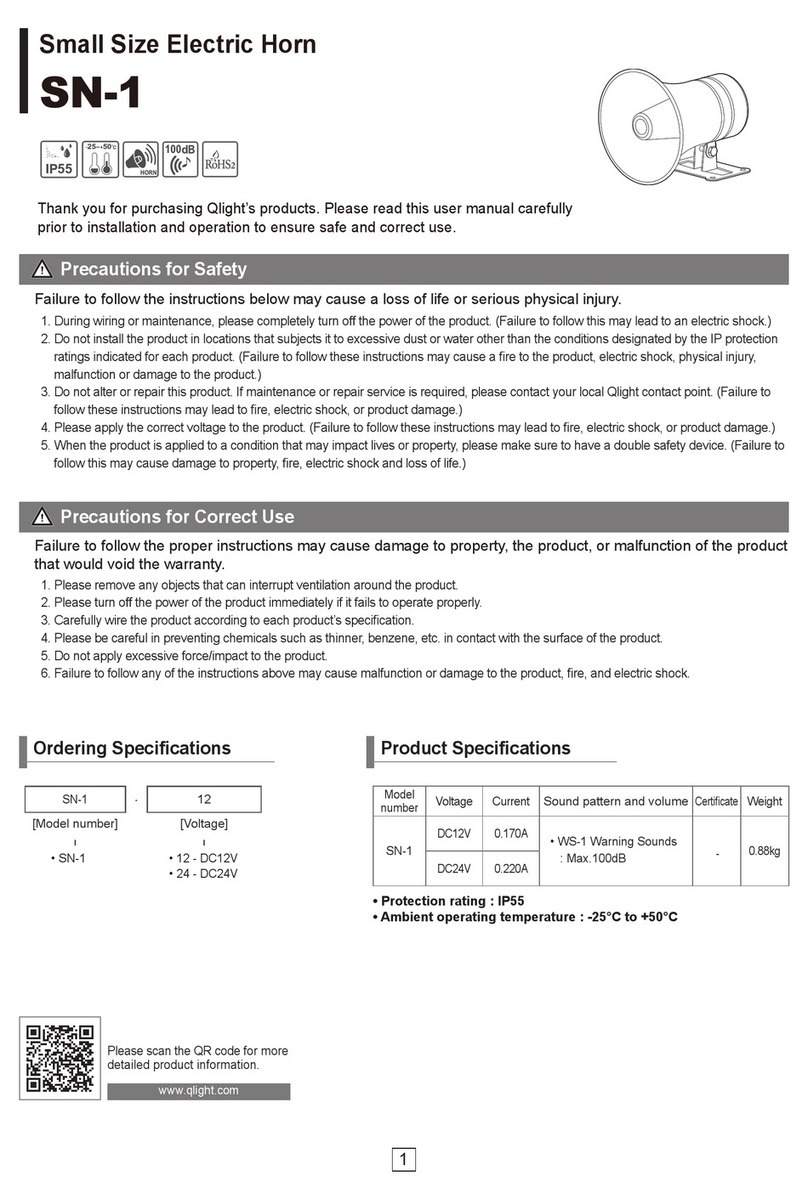
DHR H300 Series User manual

Den Haan Rotterdam
TECHNICAL MANUAL
S
I
N
C
E
1
9
2
2
H300 Series

2Version 2.1 October 2015
Den Haan Rotterdam
DISCLAIMER
Despite constant care and attention DHR puts in its manuals it is still possible that information in
this manual is incomplete or incorrect.
We do not guarantee that the information in the manual is suitable for the purpose for which the
information was consulted. All information is offered in the state in which it actually is and without
any (implicit) guarantee or warranty regarding its validity or its suitability for a particular purpose
or otherwise. All illustrations are for illustrative purposes only. This manual is not intended to cover
every possible detail about the product.
We exclude all liability for any damages, direct or indirect, of any nature whatsoever, arising from or
in any way connected with the use of this manual. In addition we are not liable for damages, direct
or indirect, arising from the use of information obtained from this manual.
A user of this manual may not publish copyright protected works or other information from the ma-
nual or in any way reproduce the information without our permission. This also includes the repro-
duction of information or parts thereof by publication in an electronic (computer) network.
© Copyright, Den Haan Rotterdam B.V.
Version 2.1 October 2015
This document contains proprietary information that is protected by copyright.
All rights reserved.
WARNING!
- Wear ear protection when handling air horn.
!

4Version 2.1 October 2015
Den Haan Rotterdam
Application:
• Sea-going vessels with a length of less than 75 metres
• Rhine and European inland navigation vessels
Type tested by:
TNO, Dutch institute of Applied Physics
Materials:
• Housing: solid brass - chromium plated
• Membrane plate: Phosphor bronze
Sound pressure level:
• H300 120,2 dB(A)
• H310 125,0 dB(A)
• H320 130,9 dB(A)
• H330 132,6 dB(A)
Fundamental frequency
• H300 228 Hz
• H310 216 Hz
• H320 184 Hz
• H330 216 Hz
Air consumption:
1,5-2 l/s @ 1-2 Bar
Protection class:
IP X6
Operation temperature:
-25°C up to +55°C
Mounting:
Base
Connection:
1. TECHNICAL DATA

5Version 2.1 October 2015
Den Haan Rotterdam
2. PRODUCT PHOTOS

6Version 2.1 October 2015
Den Haan Rotterdam
100
70
12
Ø5,5
36,5
60
Ø5
44
Only for H320 / H330
D
L
Air hose Ø 8 x 6 mm
Type L [mm] D [mm]
H300 560 125
H310 605 125
H320 690 150
H330 780 150
[mm]
3. DIMENSIONS

7Version 2.1 October 2015
Den Haan Rotterdam
4. THE COMPLETE SET
Item Part Type Art. code
1 Air Horn H300 (STPK) 30001
H310 (STP) 30002
H320 (SBU) 30003
H330 (SBUL) 30004
2 Horn control panel AHD-WOP 40020
Push button 90002
3 Manoeuvring light DHR60 60.06.10.00
4 Relay 24VDC/65A 90001
5 Compressor DHR High air flow - 24VDC/35A 90100
Marco - 24VDC (Relay included) 90150
6 Air hose - polyamide Ø8x6 mm 90003
24VDC
24VDC
Manoeuvring light
Air horn
Compressor
Horn control Panel Relay

8Version 2.1 October 2015
Den Haan Rotterdam
5. EXPLODED VIEW
Item Part Material Quantity Art. code
1 Horn H300 - STPK 1 90011
Horn H310 - STP Solid brass - 90012
Horn H320 - SBU chromium plated and inside red 90013
Horn H330 - SBUL 90014
2 Support H320 and H330 Stainless steel 316 1 30000
3 Nut M24 x 1 Stainless steel 316 1 30023
4 Diaphragm casing c/w Solid brass - chromium plated 1 30024
mouth piece
5 O-ring Ø52 x 3 NPR - shore 70 1 30022
6 Diaphragm ring Bronze 1 30021
7 Diaphragm Phosphor bronze 1 30005
8 Cup point M4 x 6 Stainless steel A4 1
9 Lid diaphragm casing Solid brass - chromium plated 1 30020
10 Push-in coupling 1/4’’ - Ø8mm Solid brass - nickel plated 1 90005
11 Base diaphragm casing Stainless steel 316 1
2
1
4
5
6
7
3
8
9
10
11

9Version 2.1 October 2015
Den Haan Rotterdam
The best way to ensure an optimal performance is that:
• The compressor is mounted straight-up with sufficient space for cooling.
• The compressor needs exactly 24VDC. Keep the wiring between the compressor and the
power supply as short as possible.
• The air horn is mounted on a downward slope (1-2°) with no obstacles in front of the horn.
• The distance between the compressor and the air horn must be as short as possible without
any sharp curves. (max. 10 metre)
If the horn is loosened from the diaphragm casing, its recommended that the nipple of the horn is
taped be fore tightened, see figure.
Tape here
7. WIRING DIAGRAM
Horizontal
M
-
+
Fuse T1A
Relay
Compressor
Push button or
Control panel
Fuse
T60A (DHR compressor)
T20A (Marco compressor)
Air horn
24VDC
Ground
6. MOUNTING INSTRUCTIONS

10 Version 2.1 October 2015
Den Haan Rotterdam
While adjusting the air horn it’s recommended that you wear ear protection,
to prevent damage to your ears.
Although the air horn is tested and adjusted before delivering, it is possible that its setting is
changed. Altering its setting is possible by loosen or tighten the lid of the diaphragm casing. Be
aware that if you tighten the lid to far on the diaphragm casing, the diaphragm plate in the lid will
be damaged.
O-ring
Diaphragm casing
LID diaphragm casing
Cup point M4x6
8. ADJUSTING THE AIR HORN
9. MAINTENANCE
The Single-tone set is almost maintenance free. Make sure the air horn is clean and give the com-
pressor two drops of hydraulic oil monthly. Don't paint the air horn, because this can reduce the
sound pressure level and alter its frequency.
This manual suits for next models
4
Table of contents
Popular Horn manuals by other brands
Siemens
Siemens HS-MC Series installation instructions

Electro-Voice
Electro-Voice 848 engineering data
Valcom
Valcom IP Solutions VIP-9880 user guide
Vixen Horns
Vixen Horns VXH1264X2 installation guide
Vixen Horns
Vixen Horns La Cucaracha VXH6803B installation guide
Wolo
Wolo SEA SAFE 135 installation instructions


