MetalMaster HG3208VR User manual

19/3/08
HG3208VR
HYDRAULIC GUILLOTINE
MANUAL
(S960)

S960% % % %%%%%%%% HG3208VR%%%%%%%%%%%%18/3/08
QC11Y-8X3200
Hydraulic Guillotine shears
Operation Manual
Serial No.:Q709103

QC11Y% Hydraulic% Guillotine% Shear%
1
Contents
1、Application of the Machine ―――――――――――――――――2
2、Performance Parameters of Machine. ―――――――――――――――3
3、Structures of the Machine. ―――――――――――――――――― 4
4、Hoisting and Installation――――――――――――――――― ――― 6
5、Adjustment and Operation of Machine ――――――――――――――8
5.1 Preparation before operation ―――――― 8
5.2 Run trial ―――――――――― 8
5.3 Single cut ―――――――――― 9
5.4 Continuous cut ―――――――――― 9
5.5 Adjustment of cutting angle ――――――― 9
5.6 Reset of cutting angle ―――――――――― 40
5.7 Fill oil ―――――――――― 10
6、Hydraulic Driven System ―――――――――――――――――――11
6.1 Cutting principle ―――――――――― 11
6.2 Valve position print ―――――――――― 11
6.3 Valve action print ―――――――――― 12
7、Electric System of Machine ―――――――――――――――――13
7.1 General introduction ―――――――――― 13
7.2 Caution ―――――――――― 13
7.3 Electric principle chart―――――――――― 14
7.4 Electic components list ―――――――――― 15
8、Maintenance &Trouble Shooting ――――――― ―――17
8.1 Blades ―――――――――― 17
8.2 Lubrication of the machine――――――――― 18
8.3 Air pressure inspection of accumulator ―― 19
8.4 Maintenance of hydraulic system ―――― 19
8.5 Maintenance of the machine ―――――――― 20
9、Packing List ―――――――――――――――――――――― 22

QC11Y% Hydraulic% Guillotine% Shear%
2
1
.
A
p
p
l
i
c
a
t
i
o
n
o
f
t
h
e
M
a
c
h
i
T
h
i
s
m
a
c
h
i
n
e
s
u
i
t
s
t
h
e
f
i

QC11Y% Hydraulic% Guillotine% Shear%
3
2、Performance Parameters of Machine ( table 1 )
No.
Item
Data
Unit
Notes
1
Max. Cutting Thickness
8
2
Max. Cutting Width
3200
mm
3
Shear angle
2
Degree
4
Stroke times without load
7
Min-1
5
Upper knife Holder Maximum Travel
140
Mm
6
Maximum Cutting Force
280
KN
Including the
return
pressure
7
Maximum Clamping Pressure
280
KN
Vary as per
the load
8
Maximum Working Pressure of
Hydraulic System
18
MPa
9
Adjustment Range of Back-gauge
10-1000
mm
10
Table Height Above Floor
800
mm
Model
Y132M-4B5
Power
7.5
kw
11
Main Motor
Speed
1440
R/min
Model
NT3-G25F
Flow
25
ml/r
12
Oil Pump
Pressure
31.5
Mpa
Length
3850%
Width
2200%
13
Overall
Dimensions
Height
1980%
mm
14
Machine Gross Weight
6800
kg

QC11Y% Hydraulic% Guillotine% Shear%
4
3
、
S
t
r
u
c
t
u
r
e
o
f
t
h
e
M
a
c
h
i
n
e
3
.
1
F
r
a
m
e
:
W
e
l
d
e
d
s
t
e
e
l
c
o
3
.
2
U
p
p
e
r
k
n
i
f
e
b
e
a
m
:
3
.
3
C
y
l
i
n
d
e
r
s
d
e
v
i
3
.
4
H
y
d
r
a
u
l
i
c
s
y
3
.
5
C
l
a
m
p
i
n
g
d
3
.
6
B
l
a
d
e
I
t
c
o
n
s
i
3
.
7
E
l
I
t
c
o

QC11Y% Hydraulic% Guillotine% Shear%
5
3.7.1 Panel fig of switchboard (chart 1)
NO.
Function explanation
1
Power indicator
2
Power switch
3
Cutting angle increase
4
Back gauge distance decrease
5
Back gauge distance increase
6
emergency stop
7
Oil filling button
8
Main motor stop
9
Main motor start
10
cutting stroke adjustment
11
Adjusting\single cutting\continuous cutting switch
12
Cutting angle decrease
13
Back gauge value displayer (E10)
14
Cutting angle position indicator

QC11Y% Hydraulic% Guillotine% Shear%
6
4、Hoisting and Installation
4.1.Hoisting
4.1.1The machine has lift holes at the top for hoisting . Pls choose proper steel ropes and hoisting equipment as per the machine weight. Accidents will occur if the hoisting is not effected properly.
4.1.2 The basis of the machine
The earth around the basis should be solid , and the depth depends on the specific condition.
4.1.2.1 Basis draw(chart2)

QC11Y% Hydraulic% Guillotine% Shear%
7
4.2 Installation of the machine
4.2.1 When installation , remove the balling cover on the worktable , and put the
same height pad at the processing side. And put the IM ruler on the pad. And then
use the lever meter to adjust vertically and horizontally , the allowance is less than
0.2mm every 1000mm length, the left and right direction should be same. The base
depth for machine installation depends on the earth situation (but not less than
500mm.) The earth pouring work is done by twice( pls see the chart). After 15 days
from the date of first pouring, put the machine on the base and adjust horizontally
and then set the foot screws and adjust the pad iron and then make the second
pouring. After 48 hours of that, adjust horizontally and tighten the foot screws.
4.2.2 Before the machine delivery, put the knife beam to bottom dead point and
fix up with pad to prohibit accidents; after installation, pls backout the
twice fixed pads at the inner-bottom between left and right
boards, or else it will cause mechanism troubles.

QC11Y% Hydraulic% Guillotine% Shear%
8
5、Adjustment and Operation of the Machine
5.1 Preparation before the operation
A、Must backout the twice fixed pads at the inner-bottom between left and right
boards, or else it will cause mechanism troubles.
B、Clean the oil stains of the machine surface,inspect all bolts are tighten.
C、Fill the lubrication grease .
D、Clean and fill the Model L-HL 46 ordinary hydraulic oil into the oil tank。
E、The machine should be grounded , connect the power supply , the machine uses
415V/50HZ power.
F、Tighten all hydraulic pipe connecting nut.
G、before the delivery of the machine, the various valves have been locked
properly and tightly. Pls do not adjust the handwheel freely to avoid abnormal
action of the machine and avoid loss.
H、the air pressure of accumulator has been setted to 5~6 MPa before delivery,
need not to adjust unless you have special situation
5.2 Run Trial
A、Power on and turn the power switch to “1 ”.
B、Push the motor button , and start the main motor. Inspect the motor(use the
same axis with oil pump) and make sure that the motor rotation direction should
conform to the oil pump marked direction. If not conformed, pls change the input
phase . But do not change the inner connection. When conformed, start main
motor.
C、Because the knife beam is on the bottom dead point, pls reset it.
1)Turn the switch on the penal to adjust function

QC11Y% Hydraulic% Guillotine% Shear%
9
2)Press oil filling button and angle increase button meantime, adjust the
filling pressure to 14~16 MPa and keep 2~3 seconds.
3)Loose the angle increase button first, then loose oil filling button, knife
beam return.
4)Turn the switch on the penal to cutting function
D、Turn the hand wheel according to the plate thickness and adjust the blade
clearance
E、Adjust the back gauge distance according to the plate length.
F、After above action is finished, then Stamp the foot switch and start the cutting.
G、Push the red button “EMERGENCY STOP” when machine is abnormal or
when you want to stop the machine.
H、After the machine is tested fine under both no load operation and load operation,
then you can make the machine into formal production. If find the machine is
abnormal, you will have to correct the problems and then put into production.
5.3 Single cutting
Turn the switch on the penal to single cutting mode, then stamp the foot switch, the
knife beam moves down and starts to cut. The cutting is finished when moves to
the lower limit SQ3 or when you release the foot switch. After complete the cutting
stroke, the machine will automatically moves up until it is up to the upper limit
SQ4 . If the plate is not cut off completely, pls do not release the foot switch to
avoid the hurt of plate.
5.4 Continuous cutting
Turn the switch on the penal to Continuous cutting mode, stamp the foot switch
and press the pump start button at the same time, then loose them, The knife beam

QC11Y% Hydraulic% Guillotine% Shear%
10
will automatically repeat the action of single mode until that times are up or switch
is turned off . Anyway we do not encourage customers to use this mode as the
machine runs quickly and sometimes may hurt the plate or accident occurs.
5.5 Adjustment of cutting angle
Turn the switch to adjust mode, press the angle decrease or increase button to
decrease or increase cutting angle; after adjustment, turn the switch to cutting
mode.
5.6 Reset of cutting angle(oil compensation of the series oil circuit )
The cutting angle is set up to be 2 degree originally. After many times angle
adjustment, 2 degree maybe not obtainable, and in this situation the angle can be
recovered back to 2 degree. (This item also suits the oil compensation of the series
oil circuit). The procedure is as below: turn the switch to adjust mode, stamp the
foot switch , then push the angle increase button. When the knife beam moves
down to the dead point, hold on the button for a few seconds and then release the
angle increase button , then release the foot switch . After adjustment is finished,
turn the switch to cutting mode.
5.7 Oil filling
When the machine have been operated for a period of time, the return pressure may
be consumed a lot, in this situation the knife beam can not return to the dead point,
so we will have to fill the oil in this case. Oil filling procedures as below: turn the
button on the panel to adjust mode, push the oil filling button, the knife beam
moves down to the dead point, , adjust the overflow valve up to pressure around
14~16Mpa, the pressure will be displayed by pressure meter(17). When filling is
finished, turn the button on the panel to cutting mode.
QC11Y% Hydraulic% Guillotine% Shear%
11
6
、
H
y
d
r
a
u
l
i
c
D
r
i
v
e
n
S
y
s
t
e
m
6
.
1
C
u
t
t
i
n
g
p
r
i
n
c
i
p
l
e
:
W
h
e
n
s
t
a
m
p
t
h
e
f
o
o
t
s
w
i
t
c
h
,
Y
V
1
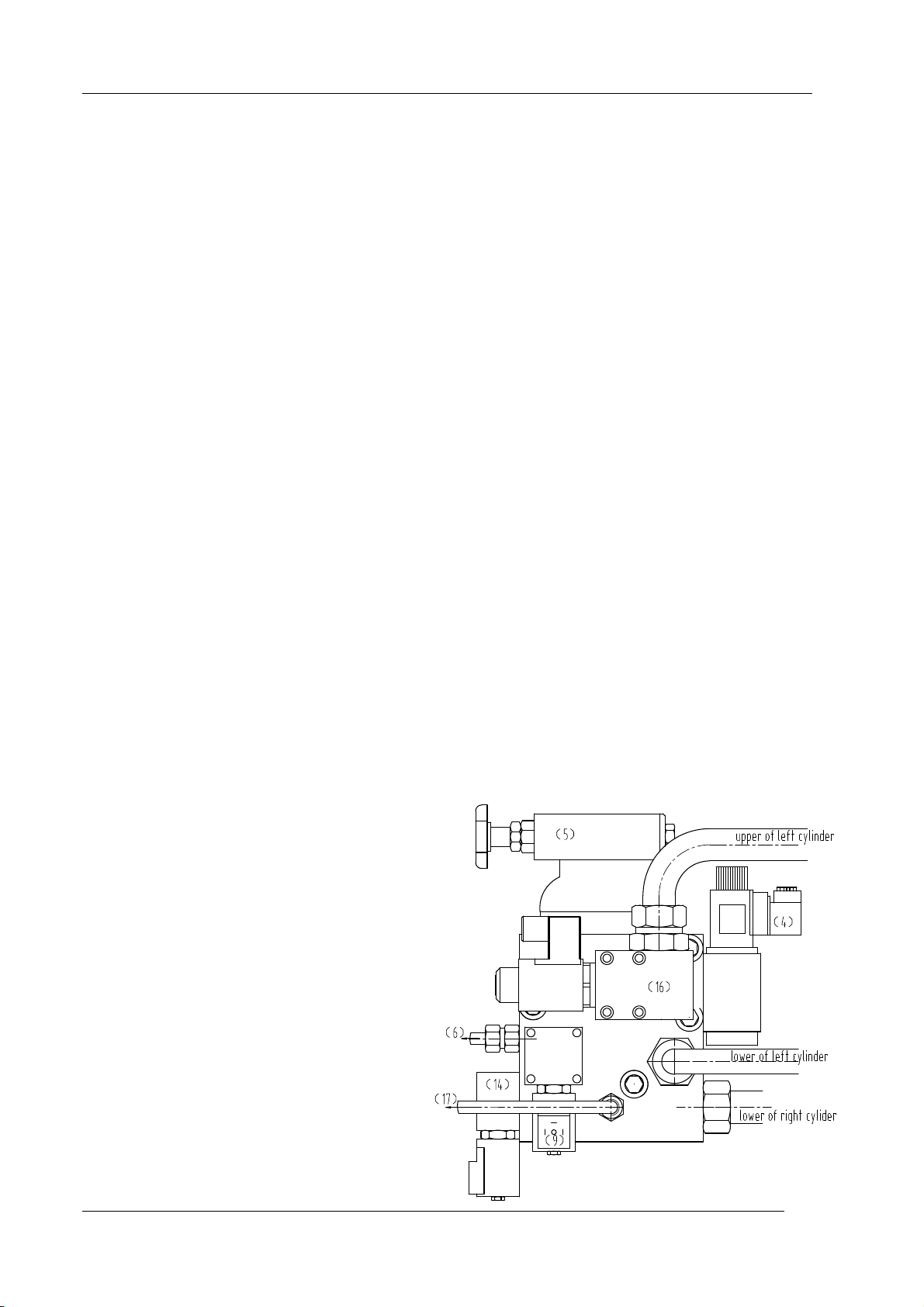
6.2 、
v
a
l
v
e
p
o
s
i
t
overflow valve(5)
m
a
i
n
p
r
e
s
s
u
r
e
e
l
e
c
t
r
o
m
a
g
n
e
e
l
e
c
t
r
o
m
a
g
n
p
r
e
s
s
u
r
e
m
e
l
e
c
t
r
o
m
a
a
n
g
l
e
a
d
e
l
e
c
t
r
o

QC11Y% Hydraulic% Guillotine% Shear%
12
6.3 Hydraulic principle print(chart 4)

QC11Y% Hydraulic% Guillotine% Shear%
13
7、Electric System of Machine
7.1
General introduction
:
The machine adopts the three-phase 415V power supply. 24V to A.C. control circuit; 27V and then 24V to D.C. Light power is AC 220V; output of the transformer is supplied to control circuit.The machine connects the ground safely. The electric components of the machine
are maily installed inside the electric box and control panel. Pls refer to our electric components list for introduction of these components.
7.2 Caution:
7.2.1 This machine is special tool, so users should arrange special operators.
The operators should read this operation manual very carefully and receive
training by our plant. Operators can run this machine only under approval of
our technicians by training. People without training can not run this machine
to avoid loss and hurt.
7.2.2 Operator should lock the SA1 key button and turn off the power switch
at the electric box when leaves . Make sure the machine is power off when
no operator.The machine should be grounded properly.
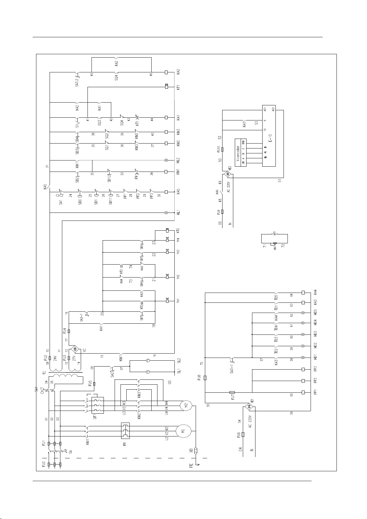
7.3 Electric principle print(refer to chart 5)
7.4 Electric components list (refer to table 2)
QC11Y% Hydraulic% Guillotine% Shear%
14
Electric principle print(chart 5)

QC11Y% Hydraulic% Guillotine% Shear%
15
Electric components list(table 2)
Code
Item
Model
Specs
Usage
KM1
AC connector
LC1-D2510B7
4《0》+1《C》
Oil pump motor control
KM2
AC connector
LC1-D0901B7
3《0》+1《C》
Backgauge motor control
KM3
AC connector
LC1-D0901B7
3《0》+1《C》
Backgauge motor control
KA5
AC connector
LC1-D0901B7
3《0》+1《C》
Backgauge motor control
KA1
Middle relay
LC1-D0901B7
3《0》+1《C》
process control
KA2
Middle relay
LC1-D0901B7
3《0》+1《C》
process control
KA3
Middle relay
process control
KA4
Middle relay
RXM-AAB2B
D+ MY4NJ
3《0》+1《C》
3《0》+1《C》
process control
FR
Heat relay
LR2-D1322
Heat protection of oil pump motor
QF
Air switch
NS80H-MA
32A
Power control of whole machine
QF1
Breaker switch
C65N 3PC3A
3P 4A
Back gauge motor circuit overload
protection
SQ1
Limit switch
TZ-9208
1《0》+1《C》
Back gauge front limit
SQ2
Limit switch
TZ-9208
1《0》+1《C》
Back gauge back limit
SQ3
Limit switch
TZ-9208
1《0》+1《C》
Knife beam upper limit
SQ4
Limit switch
TZ-9208
1《0》+1《C》
Knife beam lower limit
SA1
Key switch
ZB2-BG21
2《0》
power of control
SA2
change switch
ZB2-BD21
1《0》
Alignment Light switch
SA3
Change switch
ZB2-BD33
2《0》+《C》
Selection of adjust/single
SB0
Emergency stop
ZB2-BS542
1《C》
Emergency stop
SB1
Emergency stop
ZB2-BS542
1《C》
Emergency stop
SB11
Emergency stop
ZB2-BS542
1《C》
Emergency stop
SB2
Start button
ZB2-BW3361
1《0》
Oil pump start button
SB12
Control button
ZB2-BA42
1《C》
Oil pump stop
SB3
Control button
ZB2-BA51
1《0》
Control the positive rotating of back
gauge motor.
SB4
Control button
ZB2-BA51
1《0》
Control the reverse rotoation of the
back gauge motor
SB5
Control button
ZB2-BA31
1《0》
reduce the cutting angle

QC11Y% Hydraulic% Guillotine% Shear%
16
SB6
Control button
ZB2-BA31
1《0》
Enlarge the cutting angle
SB7
Control button
ZB2-BA31
1《0》
Oil filling
HL1
Indicator
XB7-EV61
AC 24V
Indicator of power on or off
HL2
Indicator
DL1-CEO024
AC 24V
Start Indicator of oil pump motor
Indicator
TPN-082
DC 24V
HD1-
HD5
Indicator
TPN-082
DC 24V
Limit switch
TZ-1308
1《0》
TD1-
TD5
Limit switch
TZ-1308
1《0》
KT1
Time relay
ST3PA-Y
AC 24V
Motor start delay
KT2
Time relay
JSS21-A
DC 24V
Cutting angle decrease delay
KT3
Time relay
JSS21-A
AC 24V
Cutting angle decrease delay
VE1
Switch power
S-145-24
145W
Supply direct current power
VE2
Switch power
S-35-24
35W
Supply direct current power
TC
Transformer
JBK5-500VA
415V/220V 24V
Supply control circuit power
S1
Foot switch
JWL1-11
1《0》
Control of knife moving down
FU1
Fuse box
C65N 3PC32A
3P 32A
System short circuit protection
FU2
Fuse box
C65N 1PC6A
1P 6A
System short circuit protection
FU3
Fuse box
C65N 1PC6A
1P 6A
System short circuit protection
FU4
Fuse box
C65N 1PC6A
1P 6A
System short circuit protection
FU5
Fuse box
C65N 1PC1A
1P 1A
System short circuit protection
FU6
Fuse box
C65N 1PC6A
1P 6A
System short circuit protection
FU7
Fuse box
C65N 1PC1A
1P 1A
System short circuit protection
FU8
Fuse box
C65N 1PC6A
1P 6A
System short circuit protection
FU9
Fuse box
C65N 1PC1A
1P 1A
System short circuit protection
FU10
Fuse box
C65N 1PC1A
1P 1A
System short circuit protection
PF
Photoelectric
switch
BEN
10M-TFR2
DC 24V
Back protection
Position
Indication
E-10
DC 24V
Encoder
ENC-100-A

QC11Y% Hydraulic% Guillotine% Shear%
17
8、
Maintenance &Trouble Shooting
8.1 Blades
8.1.1 T
he blade clearance (blade gap) adjustment:
It is a very important factor to adjust the blade clearance which relates the cutting quality and knife life. Pls follow below procedures: the clearance data is 0.07~0.1 times of the plate thickness, the plate thickness =0.07~0.1t. The above is for Ob=450-500N/mm2.For more
than450-500N/mm2, it is suggested to use smaller clearance. And for less than 450-500N/mm2, pls use larger clearance. Turn the handwheel in the front of the plane board to adjust the clearance data. That means adjust the clearance according to the plate thickness. The data will
be displayed on the handwheel
8.1.2
measuring of blade clearance and adjustment of the proportional clearance
the proportional clearance relates the cutting quality directly. It is set up by the manufacturing and unnecessary to modify normally. After the machine has been used for a period of time and if the knife side is changed, then it is a must to adjust the blade clearance again . The
adjustment procedure is as below: turn the switch to adjust mode, adjust knife beam to balance( cutting angle is 0
,
Turn the clearance adjust hand wheel anticlockwise to the “smallest clearance”, turn off main motor(power on), press oil filling button, move knife beam down until
distance between upper and bottom blades is 3~5mm, adjust the bolts and nut which support bottom blade on work table, use the plug gauge to inspect the clearance. After the adjustment is finished, repeat reset course of knife beam(5.2.C).
8.1.3
The installation of the blade
After the machine has been used for a period of time, must turn over the blade sides
or change the blade. The installation of the upper blade is as below: make the upper
knife beam flat( the cutting angle is 0 ). Then turn off the screw at the lower knife to
change the blade or turn over the blade. (be careful of the sharp blade to avoid hurt.)
it is easier to change the lower blade.Just take off the upper blade cover at the
working table and turn off the screw to change the blade or turn over the blade.
8.1.4
The grinding and change of the blades

QC11Y% Hydraulic% Guillotine% Shear%
18
The blades need to be ground timely. And It is costly if do not grind the blades
timely. If the blade is not sharp enough, the blade will be hurt due to too much
pressure in cutting and the cutting quality will be affected. So pls make up a
complete blade grinding timeline according to the production status. It is
recommended to have some spare blades for replacement at any time.
Our recommended blade grinding timeline:
(1) For operation 80-100hours, pls turn over the blade sides. The upper blades and
the lower blades can be turned over three times.
(2) For operation 320-400 hours, pls grind the blade. For most severe damaged
blade, pls change the blade. After the blade grinding or when new blade is used, the
blade clearance needs to be reinspected and readjusted.
8.2
Lubrication of the machine
Good lubrication is a must for the proper machine operation and long machine life.
Pls make good lubrication as per our provided procedures.
The main areas for lubrication:
A、The guiding rod and thread rod of the back gauge. Lubricate it once a week.
( clean the thread rod off the dirt and oil stains.)
B、3 rolled guiding rails. Lubricate it every day for the initial stage of machine
running.
C、For the spare parts outside and the rolled bearings, pls lubricate it twice a week.
And pls inspect and clean the lubrication system freaquently and take good care
of them.
8.3
The air pressure inspection of accumulator(the air pressure has been setted
to 5~6 MPa before delivery, need not to adjust unless you have special situation)
When the upper knife beam returns slowly( the oil pressure is proper), pls inspect
the air pressure of accumulator. The inspection way is as below: Make the machine
power on, and do not start the main motor, turn the switch to adjust mode and push
the oil filling button, discharge the return oil pressure and then the upper knife
This manual suits for next models
1
Table of contents
Other MetalMaster Lathe manuals


Popular Lathe manuals by other brands

Encore Hartco
Encore Hartco ACE 8000 Series operating manual

Woodstock
Woodstock M1109 owner's manual

Grizzly
Grizzly G0766 owner's manual

Record Power
Record Power CL3-CAM Original instruction manual

Master Quality Power
Master Quality Power MW40018 instruction manual

Precision matthews
Precision matthews PM-1127VF-LB manual


