Pragati BTP-63 User manual

BI-DIRECTIONAL
TOOL TURRETSTOOL TURRETS
TOOL TURRETSTOOL TURRETS
TOOL TURRETS
INSTRUCTION MANUAL
JUNE 2003
BTP-63 BTP-80 BTP-100 BTP-125
vv
vv
vvv
vv
vvv
vv
vvv
vv
v

INDEX
Page
1. Principle of working. 4
2. Instructions for fitment on the machine. 6
3. Fitment of tool disc on the turret. 6
4. Operation of coolant system. 7
5. Details of electrical connections. 8
6. Electrical motor wiring diagram. 9
7. Electricalsignals. 10
8. Handcranking. 11
9. Lubrication. 11
10. Turret control flow chart. 12
11. Requirements of turret control. 13
12. Adjustment of rotary encoder. 14
13. Adjustment of proximity switch. 15
14. Replacement of the proximity switch 15
15. Assemblydrawings. 16
16. Instructions for opening of gearbox. 21
17. Instructions for assembly. 22
18. Adjustment of Ringfeder Clamps 26
19. List of spare parts. 28
20. Faults and corrective actions. 31
BI-DIRECTIONAL TOOL TURRETS
3
1. Principle of Working :
Threepieceface gearcouplingis thebasicelement usedforindexing. Couplingdesignallows thetooldisc to
be indexed without lifting. It also ensures high repeat positioning accuracy as well as rigidity.
3phase electrictorque motordrives the camshaft througha systemof gears.‘Cam shaft’drives the‘follower
shaft’in a non-uniform manner, similarto that of ‘Geneva’ mechanism. Cam shaft is alsogeared to the ‘drum
cam’ which controls clamping and release of the coupling.
Initial 90° (approximate) movement of cam shaft does not transfer any rotary movement to follower shaft.
However,thedrumcamrotatesthrough30°,whichmovementreleasestheclampingforceandpullsthesliding
couplingoutofengagement.Further180°(approx.)movementofcamshaftindexesthefollowershaftthrough
90°,which inturn, indexesthe turretby 30° or45° dependingon gearratio. Duringthis movement,drum cam
profilekeepstheslidingcouplingindis-engagedposition.Inthefinal90°movementofthecamshaft,thefollower
shaftremainsstationary.Thedrumcampullstheslidingcouplingintoengagementandappliesclampingforce
through disc spring. One revolution of cam shaft completes one indexing cycle of declamp-index-clamp.
Absolutepositionencodergivesfeed-backoftheturretposition.Proximityswitchinspectstheclampedposition
of the turret.
FIG 1.1
4
BI-DIRECTIONAL TOOL TURRET
1. Cam Shaft 2. Follower Shaft 3. Drum Cam 4. Fixed Coupling
5. Indexing Coupling 6. Sliding Coupling 7. Disc Spring 8. Torque Motor
9. Proximity Switch 10. Encoder
8
9
10
1
2
3
4
5
6
7

Diagrambelowgives relativepositionsof mechanicalelementsand electricalsignalsduring onerevolution
of the cam shaft.
CAM ANGLE
MOTOR
TURRET
CLAMP
SWITCH
BIT 1
BIT 2
BIT 4
BIT 8
STROBE
PARITY
ENCODER
POSITION
OF
COUPLING
TEETH
DRUM CAM
PROFILE
PARRALLEL
INDEX
DRIVE
1
0
1
0
1
0
1
0
1
0
1
0
1
0
1
0
1
O˚ 35˚ 9O˚ 18O˚ 27O˚ 325˚ 36O˚
FIG 1.2
BI-DIRECTIONAL TOOL TURRETS
5

6
BI-DIRECTIONAL TOOL TURRETS
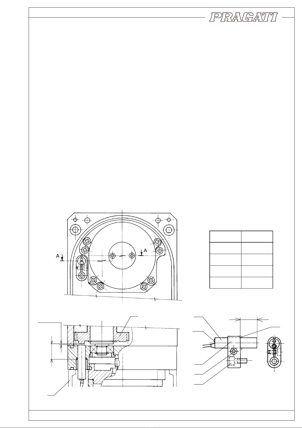
2. Fitment on the machine :
Seatingsurfaceofthemachineshouldbeflattoensureproper
contactwiththeturretbase.Machinesurfaceshouldbeeither
scraped or surface-ground.
Turret should be aligned by dialing surface of the indexing
flange.Clampingboltsshouldbetightenedafteraligningthe
seating surface, square to the lathe axis.
Clampingboltsshouldusemachinewashersofextrathickness
(min.5 mm) to ensure proper clamping.
DowelPinsarenotrecommendedforensuringthealignment
of turret. It is preferable to allow the turret to slip in the event
of an accidental shock or overload. This slipping absorbs
some of the energy of the shock and reduces the possible
damage. Turret can again be brought back to alignment by
dialing a reference surface on the tool disc.
There is one more reason for avoiding the dowel pin. Acci-
dentalcollisionsarenotun-commoninthefieldofCNClathes.
In the event of a collision, dowel pins can get sheared or
damaged.Itisadifficulttasktoremovesuchdowelpins,and
to fit new ones. New dowels may involve enlarging the
damagedholebydrillingandreaming.Thisisdifficulttodoat
the customer's place. This is a difficult operation to be done on site, and is most likely to be less than perfect.
Onthe otherhand, it isperfectly possibleto usethe turret andtool discwithout theuse of dowels.The friction
joint can easily take up normal cutting loads, including occasional over loads.
Pragati turrets, therefore, do not have a provision of dowelling the body to the base.
TOOL
DISK
3. Fitment of Tool Disc on Turret Flange :
Tool disc is to be fitted on the indexing flange with the help of
clampingbolts,andmachinewashers.Discshouldbeangularly
adjustedwithintheclearanceoftheboltholes,togetthecorrect
centre height of the tool. It should then be firmly clamped by
tighteningthebolts.Dowelpinsforensuringthepositionarenot
recommendedfor the reasons explained earlier.
However,dowelpincanbeusedforthepurposeofalignment,but
itisrecommendedtoremovethepinafterclampingthetooldisc
inposition.Thereisaprovisionofsoftareasontheindexingflange
to facilitate drilling and reaming for dowel pins.
Boltholesinthetooldiscshouldbeofextralargesizetoallowfor
angularadjustment.Extrathickmachinewashersshouldbeused
to ensure proper clamping.
TURRET
BODY
FLAT
SEATING
SURFACE
(SCRAPEDOR
GROUND)
EXTRATHICK
WASHERS
OVERSIZE
BOLTHOLE
EXTRA
THICK
WASHERS
FIG 3.1
FIG 2.1
BI-DIRECTIONAL TOOL TURRETS
7
Turrethastwoalternativepositionsfortheconnectionofcoolantpipe.Coolantpassesthroughthedrilledhole
inthebodyandentersthepassageinthecoolantring(01&24).Thisringhasspringloadedcoolantvalve.Valve
button(130)continuouslypressesagainstcoolantflange(26)fittedonindexingflange.Coolantringaswellas
coolantflange haveprovision forangular adjustment.Coolant flange shouldbe adjustedto alignthe ‘O’rings
(37)withcoolantpassagesontooldisc.Coolantringshouldthenbeadjustedtoalignthecoolantvalvewiththe
proper hole on the coolant flange (ref. 4.1). There are 2 valve positions on the coolant ring. Only one of the
positionsistobechosenasfunctional,andshouldbefittedwiththespringloadedvalvebutton(130).Theother
valve positions should be blocked by plug (136).
Thisdesignensuresthatthecoolantisconnectedonlytotheworkingtoolposition.Coolantflowautomatically
stopsduringthe indexingmovement, as thecoolant flangeclosesthe openingofthe valvebutton.
Coolant passage through the turret body, coolant ring and the valve has been designed to provide as little
resistancetocoolantflowaspossible.However,thepathislongandnarrow,withanumberofbendsintheflow
passage.Furthermore, coolant hasto pass throughdrilled passagesin the tooldisc, before reachingthe tool
point. It might therefore be necessary to employ high pressure coolant pump, to ensure sufficient flow at tool
point. Coolant passages in tool turret can withstand a maximum pressure of 6 bar.
4.1 Procedure for adjustment of coolant ring :
Coolantringholdsontotheindexingflange(27),becauseofthefrictionofwiperseals.Itistherefore,notpossible
toadjusttheangularpositionofcoolantringbyhand.Followingprocedureistobefollowedforthisadjustment.
*Loosenclamps(140).Movethecoolantringalongwithindexingflangebyhandcranking(Ref.section8,page
11) to required position. Tighten clamps (140).
INDEXING
FLANGE(27)
CLAMPSFOR
COOLANTFLANGE
(137)
COOLANTFLANGECLAMPED
TOINDEXING FLANGE (26)
CLAMPFOR
COOLANTRING
(140)
COOLANTVALVE
ADJUSTMENTRANGE COOLANTVALVE ALTERNATE
POSITION AVAILABLE ON
OPPOSITE SIDE.
COOLANTENTRYPOSITION
AVAILABLE ON OPPOSITE SIDE.
20°
20°
4. Operation of Coolant system :
FIG 4.1
COOLANT
RING(24)
4.2 Replacement of Valve Button ( fig. 4.2 ) :
Valvebutton(130)rubsagainstthecoolantflangeduring
indexing,andisliabletowear.Provisionhasbeenmade
toreplacethebutton,withoutremovingthetooldiscfrom
theturret.
Forreplacement,loosen theclamp (140)and move the
coolantringtobringthevalveinasuitablepositiontoget
access to the plug (134).
Removetheplug,thespringandthevalvebutton.Replace
withanewbutton,andplacebackthespringandtheplug.
Coolantringshouldthenbeshiftedbackandclampedin
originalposition.
01
26
24
134
37
136
FIG 4.2
27
130

5. Details of Electrical Connections
8
BI-DIRECTIONAL TOOL TURRET
1
4
2
3
1. Torque Motor 2. Proximity Switch 3. Absolute Encoder 4.Thermal Relay
BTP-100 : 1.9 KVA
BTP-80 : 1.6 KVA
BTP-63 : 1.2 KVA
BTP-125 : 2.3 KVA
PROXIMITYSWITCH
(TURRETCLAMPSIGNAL)

BI-DIRECTIONAL TOOL TURRETS
9
415/
380
220
110
BTP-125 3.2 6.3 8.0
BTP-100 2.6 4.5 7.4
BTP-80 2.3 3.9 6.3
BTP-63 1.6 3.0 5.0
BTP-50 1.3 2.6 3.3
VOLTAGEAC
MODEL
1. Unused electrical entry points to be properly plugged.
2. Electrical wiring should be brought in through water proof conduit connection. Wire braided hydraulic
hoses can serve as conduits. They also give excellent protection against damage by hot chips.
FIG 6.2 DETAILS OF ELECTRICAL TERMINALS
MOTORCURRENT(Amps)
USEFUSERATINGABOUT
THREETIMESMOTOR
CURRENT. MINIMUM6AFUSE
TO BE USED.
6. Electrical motor wiring details
MF
TC MR SSR1 SSR2
MF
MR 0V
0V
24 VDC
E
T
T
MMM
MR
TC
TC
MF
TC
Q4.0 Q4.1I3.1
OUTPUT
INPUT
PROGRAMABLE CONTROLLER (PLC)
MOTOR
3~
FUSES
R
Y
B
N
E
TORQUE MOTOR
FORWARD REVERSE SOLID STATE
RELAYS
THERMAL RELAY
130˚ C
NORMALLY CLOSED
415 VAC 2 A
SSR
415 VAC 25 A
FIG 6.1 WIRING DIAGRAM FOR MOTOR
2
1

10
BI-DIRECTIONAL TOOL TURRET
Following points should be noted while selecting control system for turret :
1. Direction of rotation of motor for shortest indexing time is to be decided by control system.
2. Indexing times of these turrets are short. It is necessary to select particularly fast PLC
(programmable logic controller) for the control of turret operations.
3. Referring to the signal diagram, value of T3 is particularly critical. Motor must come to a physical
haltwithinthistime.Otherwise,theturretwillgetde-clampedandtheproximityswitchsignalwillbe
lost.Followingmeasures aresuggested for stoppingthe motorinminimum possibletime.
a. Control should be capable of detecting the proximity switch signal within 3 to 6 ms.
b. Solid state relays should be incorporated in the motor circuit to ensure fastest possible dis-
connection.Regular contactors can beused for motor directionselection, followed by solidstate
relays, at least in two phases.
7. Electrical Signals
123456789101112
101010101010
011001100110
000111100001
000000011111
111111111111
110100110010
POSITION NUMBER
BIT 1
BIT 2
BIT 3
BIT 4
STROBE
PARITY
T1 T2 T3
ms ms ms
max
FAST
STD
FAST
STD
STD
BTP-100
BTP-80
BTP-63
110 60 50
135 75 60
100 55 45
110 60 50
80 45 35
TABLE 1 ENCODER SIGNALS TABLE 2
CCW CW
TURRET
CLAMP
SWITCH 1
0
1
0
1
0
1
0
1
0
1
0
1
0
ENCODER
BIT 1
BIT 2
BIT 3
BIT 4
STROBE
PARITY
T1T2
a
a
a
a
a
a
a
a
a
a
a
a
a
a
aaaa
CAM ANGLE
MOTOR 1
0
1
O˚ 180˚ 360˚ 360˚
180˚
POSITION 4 POSITION 5
TURRET CLAMP
POSITION 3
START
T3
T1 ms T2 ms
BTP-125 175 135
BTP-100 150 115
BTP-80 125 95
BTP-63 100 75
BTP-50 75 60

Turretcanbeindexedbycrankingtherotorofelectricmotorbyhand.Handcrankingisrequiredforinspecting
the setting of encoder and proximity switch. It is also necessary for inspecting the clamping function of disc
springs.
Procedure for hand cranking is as follows :
1. Disconnect 3 phase power supply to the motor.
2. Remove end cover (119) of motor. Hexagon head of motor shaft is now approachable.
3. Use a suitable cranked spanner to crank the motor.
4. After cranking, do not forget to place cover (119), back in position.
119 118 114
HEX.END
FIG 8.1
FIG 9.1
9. Lubrication :
Turretislubricatedbymediumviscositygearbox
oil.
Oilcanbefilledafterremovingthefillingplug(161)
as shown in the fig (9.1). A drain plug (160) has
been provided to drain out the oil, if so required.
Oil quantity required for different turret models is
listedbelow:
MODEL Oil Qty Lit.
BTP-125 1.75
BTP-100 1.25
BTP-80 1.00
BTP-63 0.75
BI-DIRECTIONAL TOOL TURRETS
11
DRAINPLUG
160
FILLINGPLUG
161
8. Hand cranking :

12
BI-DIRECTIONAL TOOL TURRETS
D
E
T4 > 4 Sec.
’TIME FAULT’
ALARM
NO
YES
TURRET
CLAMP SWITCH
ON ?
DELAY T5 ms. DELAY T5 = T3 + 5 ms.
CYCLE COMPLETE
SIGNAL
END
’TURRET NOT
LOCKED’ ALARM
NO
X=Y
TURRET
CLAMP SWITCH
ON ?
STOP MOTOR
E
E
D
D
B
NO
NO
YES
YES
X=Y ’POSITION FAULT’
ALARM
NO
YES
YES
ALARM ’INVALID
TOOL DEMAND’
START
POSITION ’X’
DEMAND
POSITION ’Y’
’N’ = NUMBER OF INDEX
POSITIONS 8,12 OR 24
DEMAND
VALID ?
1<Y<N
NO
YES
X<Y
(Y-X)<N/2 (X-Y)<N/2
START TORQUE
MOTOR ’CCW’ START TORQUE
MOTOR ’CW’
TURRET
CLAMP SWITCH
OFF ?
E
D
B
NO
NO NO
NO
YES
YES
YES
X=Y
START 4 Sec.
TIMER T4
A
NO
YES
YES
Monitor Turret clamp switch signal on
continuous basis. Generate FEED-HOL
D
if clamp signal missing.
Note :
A
10. Flowchart for turret control
NOTE:MONITORTURRETCLAMPSWITCHSIGNALON
CONTINUOUSBASIS.GENERATEFEED-HOLD
IFCLAMPSIGNALMISSING

BI-DIRECTIONAL TOOL TURRETS
13
11. Requirements of turret control :
11.1 Sequence of operation :
Suggested flow chart is given in the diagram on page 12. It might be necessary to modify the program
dependingonindividualapplications.However,followinggeneralpointsshouldbenotedwhileselecting
the control system and its program :
* Indexing times of these turrets are short. It is therefore necessary to select a particularly fast PLC
(programmable logic controller) for the control of turret operation.
* Referring to the electrical signal diagram on page 10 ; time ‘T3’ is particularly critical. Motor must come
toaphysicalhaltwithinthistime.Otherwise,theturretwillgetdeclamped,andtheturretclampswitchsignal
willbelost.
For stopping the motor in minimum possible time, following measures are required :
* Control should be capable of detecting the turret clamp switch signal within a period 5 ms.
* Motorshouldbeswitchedoffbysolidstaterelays,whichgivefastestpossibleoperation.Contactorstake
much longer time (30 to 40 ms). Suggested electrical circuit is on page 9.
* Incaseofdoubt,timedelaybetween'turretclampsignal'and'motorswitchoffsignal'shouldbemonitored
on a dual beam oscilloscope, with memory.
11.2 Safety interlocks :
11.21. 'MOTOR OVERHEAT' SIGNAL
Thermalrelayhasbeenprovidedinthemotorwindingtogiveindicationofmotoroverheating.Intheevent
ofoverheatingrelayshouldtripthemotorcontactor,andalsogive‘Motoroverheating’signaltothecontrol
circuit.Motorcontactor shouldbetripped withoutdependingon PLCsoftware.Typical circuitdiagramis
given in page 9.
11.22. 'TIME FAULT'’ SIGNAL
Timerequiredforindexingthrough180°isbetween1.3secondsto3.1secondsdependingonthemodel.
Thisis the maximum timerequiredforcompletingtheindexingoperation.Ifthe‘cyclecomplete’signalis
notreceivedevenafterthistime,thiswillbeanindicationofsomefaultintheindexingcycle.Controlcircuit
should be programmed to give a ‘Time Fault’ signal, if the ‘Cycle complete’ signal is not received within
a specified time (say 1 second more than the maximum expected time) after the ‘Cycle Start’ signal.
11.23.'TURRET NOT LOCKED' SIGNAL.
Turretclampswitchshouldbecontinuouslymonitored.Iftheclampsignalismissing,aFeedHoldsignal
should be generated to stop the machine movements. Simultaneously, ‘Turret not locked’ alarm signal
shouldalsobegenerated.
11.24. 'POSITION FAULT' SIGNAL
Attheendofindexingcycle,acheckshouldbemadetoensurethattheturrethasindexedtothedemanded
position.Iftheactualpositionanddemandedpositiondonotmatch,then‘Positionfault’alarmsignalshould
begenerated.
11.25. 'INVALID DEMAND' SIGNAL
An eight position turret cannot react to a tool demand other than 1 to 8. If any other tool position
(say 12) is demanded, the control should give out 'INVALID DEMAND' signal.
All these signals should stop the operation of the machine, and an indication should be available on the
control panel regarding the nature of the fault.
11.3 Manual mode of turret control
Control panel should have a facility to change over the turret control to manual mode. Following facilities
should be available in this mode :
11.31.’Inching’themotorineitherdirection:Duringservicing,itissometimesnecessarytorotatethemotor
for checking the functioning of the turret mechanism. Push button switches should be provided to allow
‘inching’ of the motor in either direction.
11.32. Toolindexingcycleon manual demand:Controlsystemshouldprovideafacilitytoindextheturret
into desired position by manual data entry of ‘tool demand’. This can be either by a ‘thumb wheel’ switch,
or by push button data entry through CNC panel.
Indexingcyclethroughmanualtooldemandwillbeidenticaltothenormalindexingcycle,exceptforthefact
the cycle will start even if initial signal conditions are not satisfied.
Turretcanstopinanunclampedposition,ifthepowerfailsduringtheindexingcycle.Itisthenpossiblethat
validencoderfeedbackisnotavailablebecausetheturrethasstoppedinanintermediateposition.Insuch
acase,inMDImode,thecontrolshouldchooseafixeddirectionofmotorrotation(i.e.defaultdirection)and
thenindexthe turretto demandedposition.
14
BI-DIRECTIONAL TOOL TURRETS
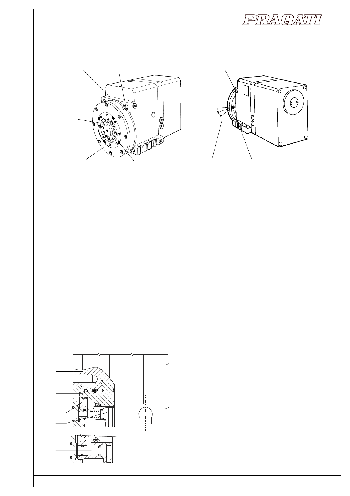
12. Replacement or adjustment of rotary encoder
Rotary encoder is fitted on flange (19) with the help of clamps (20). Encoder can be removed easily by
removing these clamps.
However, care should be taken while mounting the encoder back in its position. Angular position of the
encoder is important. Procedure for setting the encoder in proper angular orientation is as follows :
* Index the turret to any working position by hand cranking the motor shaft. Proper clamped position is
indicated by lighted LED on proximity switch (152).
* Aligntheslotofthedrivedog(23)withpin(22)onmainspindle(31)andmounttheencoderontheflange(19).
* Now rotate the encoder such that marks on encoder matches the marks on flange.
* Clamp the encoder in this position by tightening clamps (20).
FIG 12.1
A,B REFERENCE SLOTS
AB
31 22 23
SLOTONTHEMOUNTING
BLOCK(A) 19
b
13. Proximity switch adjustment and replacement (fig. 13.1)
Proximityswitchisoperatedbytheprojected‘switchingarea’ongearwheel(85);andindicatesthattheturret
is in clamped position. Actuation of the switch is indicated by built in LED (light emitting diode).
Operation of the switch can be checked by hand-cranking the turret. (refer page 11), crank motor shaft to
indexthe turret through360°. Turret willpass throughcycles of declamp-index-clamp;and your handcan
feel the pressure during ‘clamp’ phases.
Proximity switch LED should light up during all these ‘clamping’ phases. Flickering of the light, or
inconsistency of LED operation will be an indication of faulty proximity switch.
14. Replacement of proximity switch :
* Bring the turret in clamped position by hand cranking.
* Proximityswitchisapproachableafterremovingbackcover(60).Switchisheldinaclamp(153),andthe
clamp is bolted to the turret body by socket head screw (154).
* Removescrew(154),andtakeoutproximityswitchalongwithitsclamp.Measuredistance‘a’byvernier,
and note it down. Loosen clamping screw (155), and remove switch from the clamp.
* Measuredistance‘b’ betweentheclampseating surface,andthe sensingsurfaceon gear(85)byusing
avernieroradepthgauge.Distance‘a’bywhichtheproximityswitchprojectsoutfromtheclampshould
be adjusted to give a gap of 0.8 to 1 mm.
* Placenewswitchinposition.Crankturretbyhand,andcheckthefunctionofswitchbywatchingthesignals
on the built in LED.
a
152
153
156
LED
III
III
V
V
85
GAP 0.8 mm
154
155
60
FIG 14.1
MODEL Dist 'a'
BTP-125 25.5
BTP-100 25.5
BTP-80 22.5
BTP-63 23.5
BI-DIRECTIONAL TOOL TURRETS
15

16
BI-DIRECTIONAL TOOL TURRETS
FIG 15.2 VIEW WITH BACK COVER AND MOTOR REMOVED.
ACTUAL ORIENTATION OF AXES IS VISIBLE IN THIS VIEW
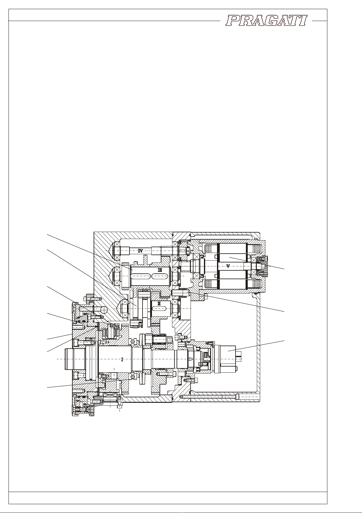
15. Assembly Drawings
FIG 15.1 OVERALL ASSEMBLY
ALL AXES ARE SHOWN IN ONE PLANE FOR CLARITY
140
141
142
151
91
90
152
153
154
86
150
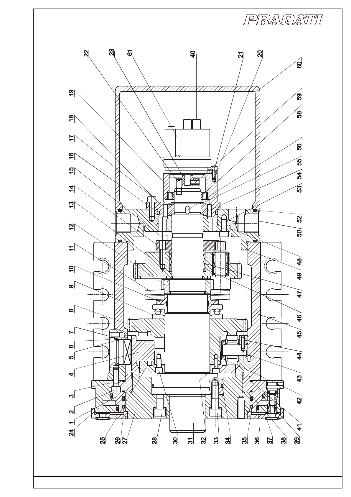
FIG 15.3 MAIN SPINDLE ASSEMBLY
BI-DIRECTIONAL TOOL TURRETS
17

18
BI-DIRECTIONAL TOOL TURRETS
FIG 15.4B INDEXING DRIVE (BTP-125, BTP-100)
FIG 15.4A INDEXING DRIVE (BTP-80, BTP-63)

BI-DIRECTIONAL TOOL TURRETS
19
FIG 15.6 MOTOR ASSEMBLY
FIG 15.5 COOLANT VALVE ASSEMBLY

1. COOLANTRING(INNER)
2. SOCHD. SCR.
3. FIXEDCOUPLING
4. SLIDINGCOUPLING
5. ‘O’RING
6. ANTIROTATIONKEY
7. SOC.HD.SCR.
8. CAMGEAR
9. THRUSTBEARING
10. SPRINGSEAT
11. DISCSPRING
12. LOCKNUT
13. INDEXINGGEAR
14. RINGFEDERFLANGE
15. SOC. HD.SCR.
16. ‘O’RING
17. SOC.HDSCR.
19. FLANGE
20. CLAMP
21. SOC. HD.SCR.
22. PIN
23. DRIVEDOG
24. COOLANTRING(OUTER)
25. CAMFLANGE
26. COOLANTFLANGE
27. INDEXINGFLANGE(COUPLING)
28. SOC. HD.SCR.
30. SOC. HD.SCR.
31. SPINDLE
32. CYL.PIN
33. SOC. HD.SCR.
34. ‘O’RING
35. SPHAGHETTI HOUSE
36. ‘O’RING
37. SEAL
38. QUADRING
39. ‘O’ RING
40. CONNECTERSTRIP
41. ‘O’RING
42. CAMFOLLOWERBEARING
43. PIN
44. GRUBSCR.
NO. NAME
Note: Please specify the model and turret number, while ordering the spare parts.
94. LOCKNUT
95. GEAR
105. CIRCLIP
106. CIRCLIP
107. OILSEAL
108. ‘O’RING
109. MOTORFLANGE
110. SOC.HD. SCR.
111. SOC.HD. SCR.
112. STATOR
113. ROTOR
114. PINIONSHAFT
115. BEARING
116. CIRCLIP
117. THREADED
118. SOC.HD. SCR.
119. COVER
120. ‘O’ RING
121. MOTORBODY
130. COOLANTVALVEBUTTON
131. ‘O’RING
132. SPRING
133. ‘O’RING
134. PLUG
135. GRUBSCR.
136. PLUG
137. CLAMP
138. CSKSCREW
140. CLAMP
141. SOC.HD. SCR.
142. SOC.HD. SCR.
150. SOC.HD. SCR.
151. CYL.PIN
152. PROXIMITYSWITCH
153. CLAMP
154. SOC.HD. SCR.
155. SOC.HD. SCR.
156. 'O'RING
160. PLUG
161. PLUG
NO. NAME NO. NAME
45. MAINBODY
46. SPACER
47. RINGFEDERELEMENT
48. BEARINGFLANGE
49. ENDPLATE
50. PLUG
51. WASHER
52. ‘O’RING
53. SOC. HD.SCR.
55. CIRCLIP
56. KEY
58. OILSEAL
59. GRUBSCR.
60. BACKCOVER
61. ENCODER
62. PINION
63. CIRCLIP
64. NEEDLEBEARING
65. 'O'RING
70. CIRCLIP
71. BEARING
72. PINIONSHAFT
73. CAMSHAFT
74. KEY
75. INDEXINGCAM
76. ROLLERHOUSING
77. PIN
78. TRACKROLLER
79. NEEDLEBEARING
80. BINDINGRING
81. GRUBSCR.
82. INDEXINGPINION
83. KEY
85. GEAR
86. BEARINGCOVER
87. KEY
88. CIRCLIP
89. SOC. HD.SCR.
90. BEARINGCOVER
91. BEARINGCOVER
92. LOCKWASHER
93. KEY
20
BI-DIRECTIONAL TOOL TURRETS
15.1 Partlist

BI-DIRECTIONAL TOOL TURRETS
21
16. Instructions for dismantling of the mechanical components
Turret may have to be opened up in following circumstances :
Mechanicaljamoftheturret.Ifturretcannotbeindexedevenbyhandcranking,itwillbenecessarytoopen
up the turret for inspection.
Unusualknockingsoundduringindexingisalsoanindicationofmechanicalproblem.Thiscanbecaused
due to accidental collision with lathe chuck or other components. If the turret does not function properly
immediately after an accident, internal component damage can be suspected.
16.1 Instructions for dismantling (fig 15.1, 15.2, 15.3)
* Remove the turret from the lathe after draining lubrication oil.
* Remove coolant flange (26) and coolant ring (24,1).
* Remove rear cover (60).
* Removemotor.
* Remove encoder (61) and mounting flange (19).
* Removegear (95).
* Removeproximity switch(152),along withits clamp(153).
* Remove circlip (55).
* Remove screws (150). Use extraction screws and pull out the end plate (49).
* Remove gear (85) after removing circlip (88), fig.15.4.
* Loosen clamping screws (15) of friction ring coupling and pull out the index gear (13).
* ShaftsII,III&IVcannowbepulledout.Ifnecessary,usethreadedholesattheshaftcentreforattaching
apuller.
* Removeanti-rotationkey(16).
* Releaseclamping bolts (2),use extraction screwsand pullout the spindleassembly.
16.2 Dismantling of disc spring and drum-cam assembly (fig 17.5)
* Considerableforceisrequiredtoloosenthenut(12).Toreleasethenut,clamptheindexgearassembly
(fig 17.5) back in position. This will engage the pinion (162) onto the gear teeth of the nut (12). Now, the
nut can be released by turning the pinon with the help of a spanner.
* In models BTP-50,BTP-63,BTP-80,the nut can be losened using a 'C'-spaner
* Drum cam assembly (fig 17.1) along with the sliding coupling (4) can now be removed.
* Remove screws (30) to seperate two parts of drum cam as well as the sliding coupling.
16.3 Inspection of mechanical components (fig 15.4, 15.3)
* Check that the cam follower bearing (42) and (72) are in good condition (8,25).
* Check that the working surfaces of indexing cam (75) and drum cam are in good condition.
* Check that wiper seals (35) and (39) are in good condition.
This manual suits for next models
3
Table of contents
Other Pragati Lathe manuals


