ATEK MAKINA JUMBO DOUBLE User manual

INSTRUCTIONS BOOKLET
Rim Press + Lathe
JUMBO DOUBLE
English

2

3
Sale Date :
Seller Company;
The Machines which are produced By ATEK MAKINA are under warranty against defects
of the material and production for one(1) Year from date of it is sold.
Our Company ATEK MAKINA is not responsible for the damages or defects due to
damages occured by faulty used and out of purpose of use.
If the Defects and damages are occured during the warranty, After making analysis by
technical staff, If the Material and production fault is found, the damaged parts will be
replaced with new one
Warranty covers all parts of the machine during the warranty.
ATTENTION: you have to put thermic switch which is suitable to motor ampere on your
electric wiring to make Electric motor under warranty otherwise in case of any defect
the Electric Motor will not be under warranty.
Do Make Maintanence of the machine periodicly, monthly, yearly, The defects,
damages which are caused by not making maintanence will not be undur warranty.
Atek Machina;
Without notice to the customer reserves the right to make changes in equipment.

4
IMPORTANT NOTICE
- The presents instructions booklet is an integral part of the product.Carefully study the warnings and
instructions contained in it. This information is important for safe use and maintenance.
Conserve this booklet carefully for further consultation.
THIS MACHINE
Is a rim pres to repair defective rims.
The machine has been designed to operate within the limits described in this booklet and in accordance with the manifacturers
instructions.
The machine must be used only for the functions for which it was expressly designed. Any other use is considered wrong and
therefore unacceptable.
The manifacturers cannot be held responsible for eventual damage casued by improper , erroneous or unacceptable use
Our firm is not responsible for printed mistakes.
IMPORTANT
This machine may be operated only by suitably trained personnel. Any work on the electrical , hydraulic ,
pneumatic systems must be conducted only by professionally qualified personnel.
10 years in the life of the machine.
CONTENTS
PAGE
CLAUSE 1 General Notice...............................................................................3
CLAUSE 2 Technical Characteristics...............................................................3
CLAUSE 3 Parts Of The Machine....................................................................4
CLAUSE 4 Introduction ……………………………….........................................5
CLAUSE 5 Packaging, transport, storage and safety …….……………........... 5
CLAUSE 6 Safety Warnings..............................................................................6
CLAUSE 7 Rim repair equipment....................................................................7
CLAUSE 8 Problems , Causes , Remedies...................................................... 7
CLAUSE 9 Installatıon........................................................................................8
CLAUSE 10 Operations and use………........................................................... 9-10
CLAUSE 11 Routine Maintenance....................................................................11
CLAUSE 12 Technical service and warranty…...................................................11
CLAUSE 13 Electric Curcuıt Plan......................................................................12
CLAUSE 14 Demontage Plan and Spare Parts List.............................................13-17
DIMENSIONS
Height .............(1.853,5 min / 2.153,5 max) mm
Lenght ............... (866,5 min / 1.032,5 max) mm
Widht ................... (1.305 min / 1.555 max) mm
WEIGHT
Net weight.................................. 455 Kg
Noise Level. ...................................75 db
TECHNICAL CHARACTERISTICS
ATEK MAKİNA Service & Garage Equipments
Hastane Mah. Hadımköy-İstanbul Cad. No:54 34555 Hadımköy - İST/TR
Tel : +90 212 771 34 69 Head Office Tel/Fax : +90 212 444 21 31
CLAUSE 1
CLAUSE 2

5
PARTS OF THE MACHİNE
FLANSH must rotate in arrow direction
RIM CONNECT FLANSH
The flansh desinged to serve different size of rims
.
CONTROL UNIT controls the
pistons movements
HYDRAULIC UNIT moves the
piston up and down position
LATHE UNIT lathes the defective rims
after repair
ACCESSORIES PROVIDED
CONTENT OF THE BOX
1. 1 pcs up support.
1 pcs down support.
2. 4 pcs support pins.
3. 6 pcs screws.
4. Provided accessories.
When the machine arrives check that it has not
been damaged during transport and that all the
accessories are present.
7
Rim to center
washer
1 - 54
2 - 56.5
3 - 57
4 - 58
5 - 59.5
6 - 60.1
7 - 63.3
8 - 64
9 - 65
10 - 66.6
11 - 72
12 - 72.5
CLAUSE 3
1. 12 pcs connetıng flanches
for different sizes of rims.
2. 1 pcs gauge.
3. 5 pcs allen head wrenches.
4. 1 pcs angular supports
1 pcs sguare supports small
1 pcs gradual supports
1 pcs side chisel supports
1 pcs sguare supports big
1 pcs sguare supports reverse
5 pcs support miles
2 pcs connectıon horoscope
5. 1 pcs lever.
6. 1 pcs lathe cutter
7. Cartoon box.

6
INTRODUCTION
Thıs Manual Has Been Prepared For Workshop Personnel Expert In The Use Of The Machıne (Operator) And Technıcıans
Responsıble For Routıne Maıntenance (Maıntenance Fıtter); Read The Manual Before Carryıng Out Any Operatıon Wıth The Rım
Repaır And/Or Packıng . Thıs Manual Contaıns Important Informatıon Regardıng :
Rım Repaır Machınes Safety
He Personnel Safety Of Operators And Maıntenance Workers
CONSERVING THE MANUAL
.
PACKING , TRANSPORT , STORAGE
All packıng,lıftıng , handlıng , transport and unpackıng operatıons are to be performed exclusıvely by expert
personnel wıth knowledge of the rım pres and the contents of thıs manual.
PACKING
Rim Repair machine is crated and stretched on wooden pallet.
LIFTING AND HANDLING
The Pallets Must Be Moved Wıth A Lıft Truck.The Equıpment Chosen Must Be Suıtable For Safe Lıftıng And
Movıng, Bearıng In Mınd The Dımensıons , Weıght , Barycentre , Justs And Fragıle Parts Not To Be Damaged.
STORAGE
Packed Machınery Must Always Be Kept In A Covered , Protected Place At A
Temperature Between –10 C To +40 C And Must Not Be Exposed To Dırect Sunlıght.
OPENING CRATES
When The Crates Arrıve, Check That The Machıne Has Not Been Damaged Durıng Transport And That All The Lısted
Parts Are Present. The Crates Must Be Opened Usıng All Possıble Precautıonary Measures To Avoıd Damagıng The
Machıne Or Its Parts. Make Sure That Parts Do Not Fall From The Crate Durıng Openıng
DISPOSAL OF CRATES
The Wood Of The Pallets And The Strech Fılm May Be Re-Used.
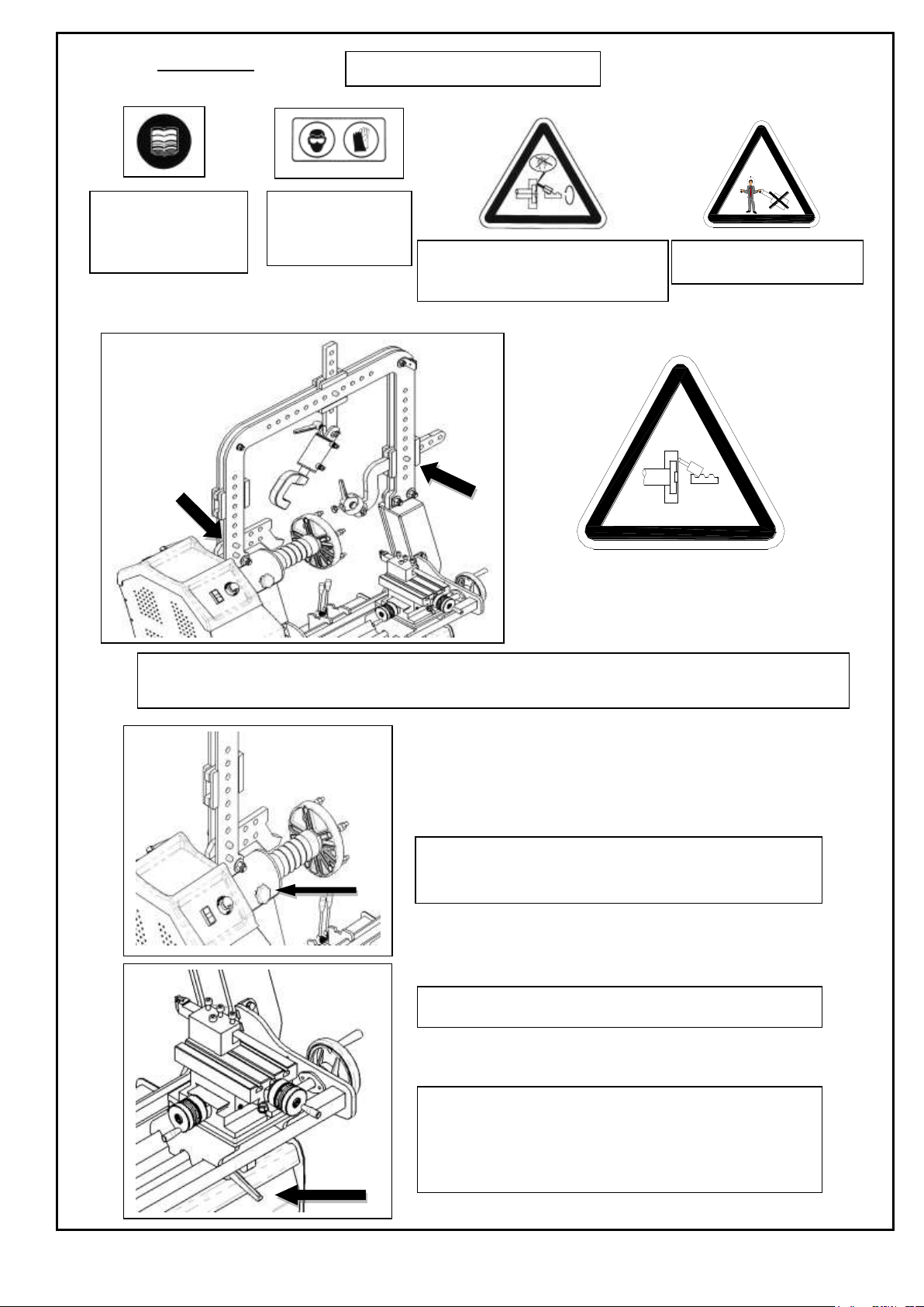
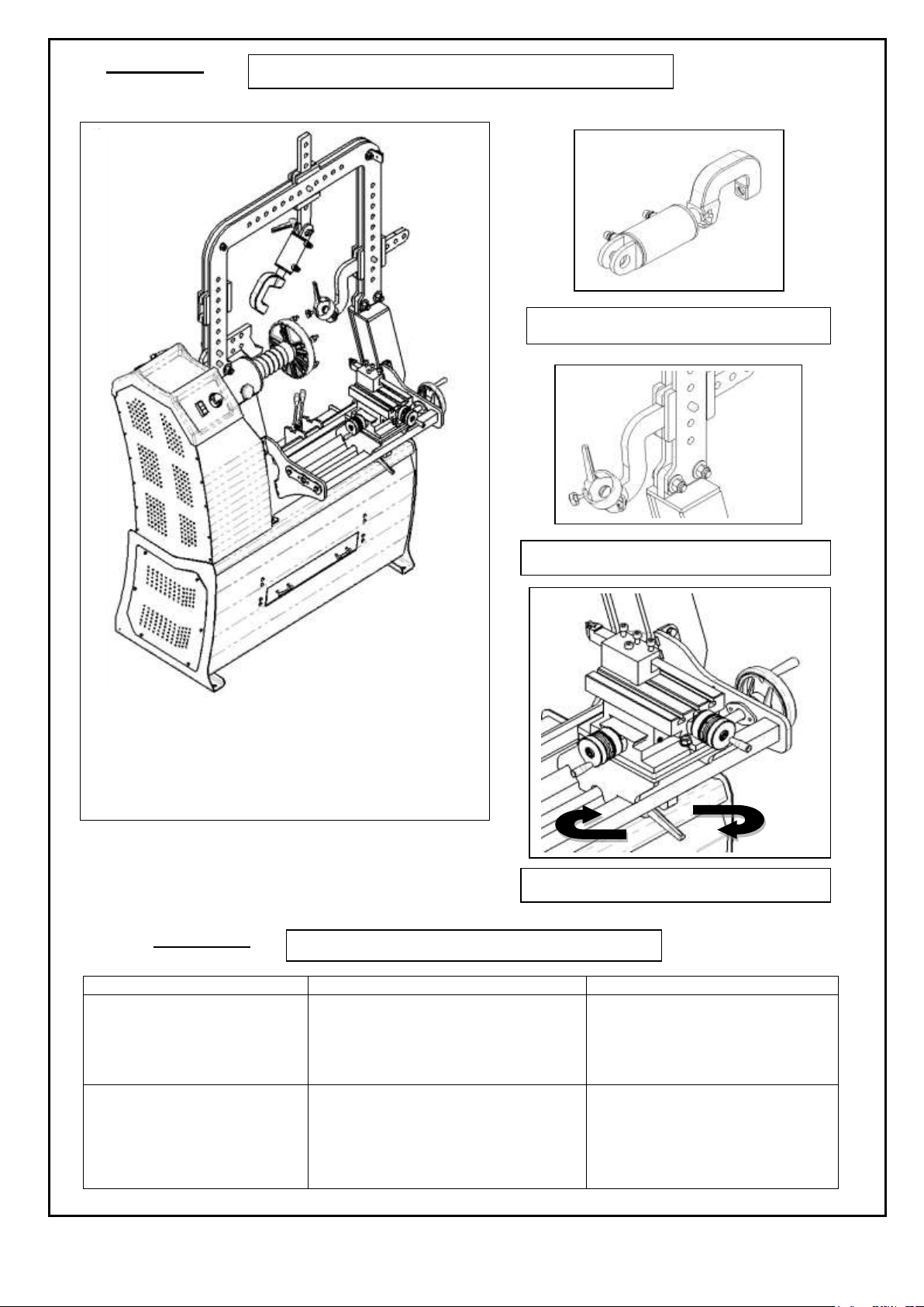
SAFETY
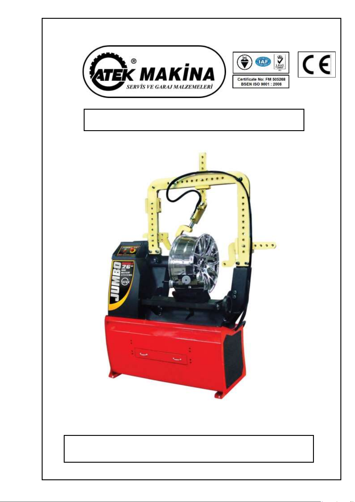
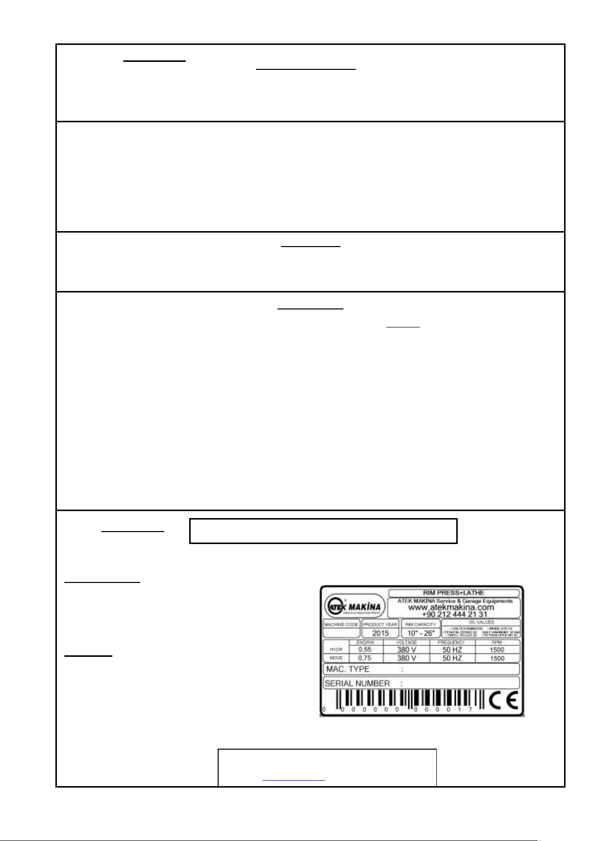
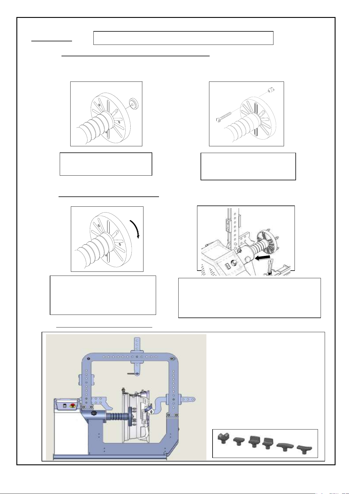
THIS MACHINE IS DESIGNED ONLY FOR 10ıı –26 ıı RIMS.
THIS MACHINE MUST BE USED ONLY FOR RIM REPAIR PROCEDURE.
PAY ATTENTION TO THE WARNING SIGNS ON THE MACHINE.
If the operator hears unusual noises or vibrations or something that may be dangerous , he must immediately press the
emergency button and switch off the main switch and check the section “Malfuctions causes and possible remedies” in
the instructions manual.If the problem is still call the service.
Wear protection glasses and gloves during the operation.
Stand straigth during operation.
Work in an insulated and clean area.
Switch off the main switch when there is no electricity.
Work in the safe distance.
The machine must be fixed onto smooth place.
DO NOT STAND IN FRONT OF THE FLANSH WHEN IT IS ROTATING.
CLAUSE 4
CLAUSE 5
The Manual Is An Integral Part Of The Rım Repaır, Whıch It Should Always Accompany Even If The Unıt Is Sold.
The Manual Must Be Kept In Proxımıty Of The Rım Repaır, In An Easıly Accessıble Place.
The Operator And Maıntenance Staff Must Be Able To Locate And Consult The Manual Quıckly And At Any Tıme.
Lıftıng, Transport , Unpackıng , Assembly , Startıng Up , Inıtıal Adjustment And Testıng , Extraordınary Maıntenance , Repaır ,
Overhauls, Transport And Dısmantlıng Of The Rım Repaır Machıne Must Be Performed By Specıalısed Personnel From The
Lıcensed Dealer Or A Servıce Centre Authorısed By The Manufacturer .
The Manufacturer Declınes All Responsıbılıty For Injury To Persons Or Damage To Vehıcles Or Objects When Any Of The Above
Mentıoned Operatıons Has Been Performed By Unauthorısed Personnel Or When The Rım Repaır Has Been Subject To Improper
Use.
Thıs Manual Indıcates Only The Operatıve And Safety Aspects That May Prove Useful To The Operator And Maıntenance Worker, In
Better Understandıng The Structure And Operatıon Of The Rım Repaır And For Best Use Of The Same.
In Order To Understand The Termınology Used In Thıs Manual, The Operator Must Have Specıfıc Experıence In Workshop, Servıce,
Maıntenance And Repaır Actıvıtıes.

7
SAFETY WARNINGS
DO NOT PUT YOUR HANDS BETWEEN
THE PISTON AND FLANSH DURING
THE OPERATION.
BE SURE THAT THE RIM IS WELL FIXED TO THE FLANSH.
TIGHT THE NUTS BEFORE THE REPAIRING PROCEDURE.
UNTIGHT THE NUTS DURING LATHE OPERATION.
”
BE SURE ABOUT ATTACHMENT OF THRUSTING PINS AND BE CAREFUL
ABOUT PISTON MUST BE WELL PLACED TO PRESSURE FOOT.
TIGHT THE FIXING HANDLE DURING LATHE OPERATION
DO NOT USE JETS OF WATER , STEAM
( HIGH PRESSURE WASH UNITS ), SOLVENTS NEAR THE RIM
REPAIR MACHINE.
UNPLUG OR SWITCH OFF THE MAIN SWITCH BEFORE YOU
START CLEANING THE MACHINE.
PLEASE READ THE
İNSTRUCTİONS
MANUAL CAREFULLY
BEFORE START
USİNG THE MACHİNE
DON’T USE YOUR
MACHINE WITHOUT
GLASSES AND
GLOVES.
DO NOT USE THE PISTON
ON LIVING THINGS.
CLAUSE 6

8
PROBLEMS –CAUSES - REMEDIES
PROBLEMS
CAUSES
REMEDIES
The flansh does not rotate in any
direction.
1.The mains connection is not plugged in.
2.The plug is not correctly wired.
3.The mains tension is not suitable for the
machine
4.The mains switch is not on.
5.Faulty fuse.
1,2,3.Check the correct insertion of the
plug and its connections.
4.Switch on the mains.
5.Replace the fuse.
The pressure of the hydraulic unit is
not enough.
1.The rotation of the hydraulic engine is reverse.
2.There is leak of oil in the connections.
3.There is lack of oil in the hydraulic engine.
1.Reverse the two wires in the connection
plug.
2.Check the couplings change them if
necessary.
3.Put some oil till the level to the hyraulic
engine.
CLAUSE 7
CLAUSE 8
RIM REPAIR EQUIPMENT
Double impact correcting piston
Correcting Piston Bedding
Slidable and Turnable Type Lathe

9
MACHINE FIXING ONTO FLOOR
LOCATION
For a good functioning the machine must be fixed onto
floor with expansion dowels.
1)Drill the floor with a helical concrete bit with a diameter of 15
mm. , using the holes in the base as a drilling template.
2)Move the rim repair and insert anchor bolts into the drills,then
set the machine in the place to be fixed.
3)Insert into the anchor bolts and use a torque wrench (setting of
25 N / m) to tighten..
SAFE DISTANCE:
For the safe and ergonomic use of the
machine it is advisable to locate it so as to
allow work, in conditions of complete safety.
ALL WORK ON THE ELECTRICAL SYSTEM, INCLUDING MINOR OPERATIONS , MUST BE CARRIED
OUT BY PROFESSIONALLY QUALIFIED PERSONNEL
Check that the mains supply is the same as that shown on the registration plate.
Connect the cable to a plug that conforms with European norms or to the norms of the country in which the
machine used.
The plug must have an earth terminal.
Check that the earth connection is effective.
The machine must be connected to the mains through a multipole isolating switch which conforms with
European norms and with contact openings of at least 3 mm.
Check that the multipole connector on the electrical board is correctly connected.
When the machine is connected switch it on and check the correct direction of rotation;this should be as shown
by the arrow on the motor unit.
If the rotation is reversed,reserve the two wires in the connection plug.
If the machine behaves abnormally,immediately press the emergency button and switch off the main switch
and check the section “Malfunctions:causes and possible remedies” in the instructions Manual.
THE MANUFACTURER DOES NOT ACCEPT ANY RESPONSIBILITY FOR THE FAILURE TO OBSERVE THE
ABOVE MENTIONED INSTRUCTIONS.
CLAUSE 9

10
OPERATIONS AND USE
CONNECTING THE DEFECTIVE RIM TO THE FLANSH
1. Clean the muds and the balance weights from the rim.
2. Choose a suitable sized
connecting flansh for the rim.
3. Tight the connecting flansh and
fasten to the suitable canals on the
flansh.
ANALYSING THE DEFECTIVE AREA
1. Rotate the flansh.
2. Locate the defective area by using
gauge and sign it.
3. Tıght The Nuts To Start The Repaırıng Procedure
4. Choose a suitable support and repair it by using the
pres.
RIM REPAIRING POSITIONS
CLAUSE 10

11
OPERATIONS AND USE
RIM REPAIRING POSITIONS
OPERATIONS AND USE
***When repairing iron rims use also the manuel handle plus to the pres.
***Before the pressing operation some rims need to be heated (especially aliminum rims). This procedure is for:
1. Avoiding cracks and faults on the rim
2. Piston’s safety
3. Your personel safety
***If the rim is too defected first mend it with the lever and then repair it with the pres..
LATHE OPERATION
*** TIGHT THE FIXING HANDLE DURING
LATHE OPERATION.
***UNTIGHT THE NUTS DURING LATHE
OPERATION
Lathe operation: this procedure is for cleaning the burrs and the overplus parts of the welding operation.
1) With the help of double impact cylinder, it can press both as pulling and as pushing.
2) Moving thrusting part to left, right, up and down, can do the best repairing process.
3) Damages on rim from in to out, out to in, front and back can be pressed as shown in the figure.

12
ROUTINE MAINTENANCE
To gurantee the efficiency of the machine and for its correct functioning is
essential to carry out routine cleaning and maintenance.
Routine maintenance must be carried out by the user according to the maker’s instruction.
** Before starting any cleaning or maintenance switch off the main switch and remove the mains plug from socket.
EVERY DAY...
Clean and grease the flansh and the lathe.
EVERY MONTH...
Check the oil level of the hydraulic system.
Tight the screws of the lathe unit.
EVERY 6 MONTHS...
Grease the bearings.Make a general check.
EVERY YEAR...
General Check: Visual inspection of all structural parts and mechanisms to qurantee that there are no problems or
anomailes.
Electric Plant:Skilled electricians should test the electric plant.
STORAGE
PERIODS OF INACTIVITY
PERMANENT STORAGE
During the times the machine is temporarily stored
or whenever the machine is not in use,remove the plug
from the mains.
If it is decided to store the machine long term it is
advisable to make it inoperative by removing the mains
cable after having unplugged it from the mains.
TECHNICAL ASSISTANCE AND SPARE
PARTS
THE MACHINE IS GURANTEED (1 YEARS)
FOR ANY MACHINE MAFUNCTIONS CONSULT THE SECTION “MALFUCTIONS: CAUSES AND POSSIBLE REMEDIES” . ANY
OTHER MALFUNCTIONS MUST BE CHECKED BY PROFESSIONALLY QUALIFIED PERSONNEL.
IN ALL CASES CONTACT THE ASSISTANCE SERVICE OF HATCO. FOR PROMPT ASSISTANCE IT IS IMPORTANT AT THE
TIME OF THE CALL TO SPECIFY THE MACHINE MODEL, THE PRODUCTION NO. (FOUND ON THE REGISTRATION
PLATE) AND TYPE OF MALFUNCTION
WARNING
ANY WORK ON THE ELECTRICAL, HYDRAULIC AND PNEUMATIC SYSTEMS MUST BE
CARRIED OUT ONLY BY PROFESSIONALLY QUALIFIED PERSONNEL.
***THE MOTORS ARE NOT UNDER WARRANTY.
THERE IS NO OIL IN THE HYDRAULIC
The machine is provided without oil in the hyraulic unit.Put some oil till the level to the
hyraulic unit from the oil can that you can find in your accessories box provided with
your machine.
Use only SHELL TELLUS 37 in the hydraulic unit
Run the machine idle for 10 minutes during the winter months. Start work later please.
WARNINGS
USE ONLY ORIGINAL PARTS OF THIS MACHINE
THE MANUFACTURER TAKES NO RESPONSIBILITY OF THE NONORIGINAL PARTS
TO ORDER SPARE PARTS:
INDICATE THE SERIAL NUMBER OF THE MACHINE AND THE YEAR BUILT.
INDICATE THE CODE OF THE PIECE REQUESTED.
INDICATE THE QUANTITIY REQUIRED.
CLAUSE 11
CLAUSE 12

13
MADDE 13
MP MPMP 5V U W V U9 8 7 6 4 W 3 2 1
SWITCH
ELECTRICAL PLAN
CLAUSE 13

14
DEMONTAGE PLAN
CLAUSE 14
01 0275 07

15

16
NO
PART. NR.
DESCRIPTION
1
84 01 000
Lower Body Group
2
84 01 001
Body Group
3
84 01 003
Fixing Plate Of Drawer Slider
4
84 01 004
Lower Body Cover
5
01 0073 016
Imbus Bolt Screw
6
01 0200 02
Switch.
7
01 0112 05
Washer
8
01 0071 010
Imbus Bolt Screw
9
01 0112 08
Washer
10
84 01 002A
Drawer Body Group
11
84 01 002B
Drawer Body Plate
12
84 01 002C
Connection Plate Of Drawer Slider
13
01 0052 33
Handhold
14
01 0052 110
Telescopic Rail
15
01 0113 010
Screw
16
01 0112 004
Washer
17
01 0117 004
Fiber Nut
18
01 0117 005
Fiber Nut
19
01 0112 05
Washer
20
01 0071 016
Imbus Bolt Screw
21
01 0070 010
Imbus Bolt Screw
22
84 02 000
Upper Body Group
23
84 02 001
Body Group
24
15 05 001
Main Shaft
25
15 10 001
Occurente Ring Back Cover
26
15 08 001
Rim Connect Flash
27
15 12 000
Baserotor Hoop
28
15 15 000
Piston Pendent
29
26 10 000
Rim Centering Group
30
01 0014 176
Record Body
31
55 04 000
Bottom Piston Clothes Tree
32
01 0024 020-3
O-Ring
33
15 14 004
Nut
34
01 0021 35-46.3-10
Wipper
35
01 0024 060-3
O-Ring
36
01 0024 035-3
O-Ring
37
01 0022 060-044
Compact Set
38
15 14 003
Hydraulic Cylinder Piston
39
15 14 001
Hydraulic Cylinder
40
84 02 002
Hose Clamp
41
01 0072 020
Imbus Bolt Screw
42
01 0053 06016-YW
Bearing
43
01 0139 080
shaft ring
44
01 0081 016
Counter Screw Rivet
45
01 0074 035
Imbus Bolt Screw
46
01 0124 020
Setscrew
47
01 0072 010
Imbus Bolt Screw
48
01 0114 42
Fixing Screw
49
01 0064 080-1.5
Bolt
50
01 0115 001
Rim Connect Nuts.
51
01 0075 030
Imbus Bolt Screw
52
01 0112 10
Washer
53
01 0063 025
Bolt
54
01 0131 1-4
Copper Flake 1/4
55
01 0115 010
Bolt
56
84 06 001
Engine Connection Sheet Metal
57
01 0112 08
Washer
58
01 0062 030
Bolt
59
01 0275 07
Engine
60
15 34 000
Engine Hoop
61
01 0013 1325
V –Belt ( 13*1325 )
62
84 03 000
Lathe Unit group
63
84 03 001
Right Connection Group Of Lathe Unit
64
84 03 002
Left Connection Group Of Lathe Unit
JUMBO DOUBLE PARTS LİST

17
65
84 03 003
Sport Skidding Metal Sheet
66
84 03 004
Sport Handling Axle
67
84 03 005
Bearing Stopping Plate
68
84 03 006
Supporting Plate For Arm Connection
69
01 0112 08
Washer
70
01 0073 025
Imbus Bolt Screw
71
01 0064 025
Bolt
72
01 0112 10
Washer
73
01 0063 025
Bolt
74
01 0139 017
Shaft Ring
75
01 0053 06203-FAG
Bearing
76
01 0315 005
Swivel Arm
77
01 0315 004
Wheel
78
84 03 007A
Body Group
79
84 03 007B
Sport Turning Plate
80
84 03 007C
Slider Locking Plate
81
84 03 007D
Fixing Screw
82
84 03 007E
Square Nut
83
15 37 001
Grooving Holder Connecting Equipment
84
01 0074 070
Imbus Bolt Screw
85
01 0074 035
Imbus Bolt Screw
86
01 0050 01
Fixed Sport
87
01 0047 02
Tool Bit ( Lathe Cutter )
88
01 0083 90
Bolt
89
01 0112 12
Washer
90
01 0117 012
Fiber Nut
91
01 0114 05
Lathe Unit To Stop Switchcrank
92
84 07 000
Hydraulic Unıt Group
93
01 0159 27
Power Unit
94
01 0014 176
Record Body
95
01 0131 1-4
Copper Flake 1/4
96
01 0014 79
Record Thimple
97
01 0014 23C
Pipe Squeezing Nut
98
01 0014 211
Record
99
01 0131 3-8
Copper Flake
100
01 0014 20
Record Body
101
01 0157 06
Hydraulic Valve
102
84 07 001
Hydraulic Unıt Connection Sheet Metal
103
01 0112 06
Washer
104
01 0061 020
Bolt
105
01 0117 006
Fiber Nut
106
01 0112 08
Washer
107
01 0115 008
Bolt
108
84 05 000
Cabin Group
109
84 05 001
Cabin Right Body Group
110
84 05 002
Cabin Left Body Group
111
84 05 003
Cabin Top Body Group
112
84 05 004
Cabin Inner Cover Plate
113
84 05 005
Cabin External Cover Plate
114
01 0039 121
Top Cover.
115
01 0030 49
İgnition
116
01 0030 73
İgnition
117
01 0030 20
Hydraulic Unit Start-Stop Switch
118
01 0030 95
Button
119
01 0030 97
Button
120
01 0107 040
Screw
121
84 04 000
Bridge Group
122
84 04 001
Bridge Body Plate
123
84 04 002
Bridge Interconnection Bush
124
84 04 003
Thrust Moving Tap Group
125
84 04 004
Linear Thrust Plate
126
84 04 005
Bottom Thrust Plate
127
84 04 006
Top Thrust Plate
128
84 04 007
Switchblade Pin Group
129
84 04 009
Repairing Piston Bedding Group
130
15 13 001
Hydraulic Cylinder Supports Pin Set.

18
131
84 04 010
Hose Fixing Plate
132
84 02 002
Hose Clamp
133
01 0072 020
Imbus Bolt Screw
134
01 0114 04
Bakelite Bolt
135
01 0117 014
Fiber Nut
136
01 0065 070
Bolt
137
01 0069 3-4
Bolt
138
01 0112 3-4
Washer
139
01 0117 3-4
Fiber Nut
140
01 0112 14
Washer
141
84 04 008A
Piston Body Group
142
84 04 008B
Body Group Piston Shaft
143
84 04 008C
Hydraulic Cylinder Nut.
144
84 04 008D
Presser Foot Puller Plate
145
84 04 008E
Presser Foot Fixing Pin
146
01 0140 012
Segment
147
01 0031 112
Arc
148
01 0131 3-8
Copper Flake
149
01 0014 176
Record Body
150
01 0024 035-3
O-Ring
151
01 0024 070-3
O-Ring
152
01 0022 070-50-22.4
Compact Set
153
01 0021 35-46.3-10
Wipper
154
84 01 005
Electrıc Panel Group
155
84 01 005A
Connection Plate
156
01 0202 03
Transformer
157
01 0196 27
Contactor
158
01 0028 42
Cable Canal
159
01 0028 64
Klemenes Rail
160
01 0028 42-K
Cable Canal Cover
161
01 0028 26
Klemenes
162
01 0028 169
Insured Klemenes
163
01 0028 29
Klemenes
164
01 0028 28
Klemenes (Ground)
Table of contents