Pragati BTP-50 User manual

I N S T R U C T I O N M A N U A L
B T P - 50
BI-DIRECTIONAL
TOOL TURRET
IMB50052014


BI-DIRECTIONAL TOOL TURRET 3
IMB50052014
Index
1. TURRET IDENTIFICATION 5
2. TECHNICAL INFORMATION 6
6gnikroWfoelpicnirP1.2
6serutaeflaicepS2.2
7sliatedlanoisnemiDdnalacinhceT3.2
3. INSTALLATION 8
8enihcamehtnotnemtiF1.3
8metsystnalooC2.3
9csidlooTehtfotenmtiF3.3
10snoitcennoclacirtcelE4.3
11sliatedgniriwrotoM1.4.3
4.1 Electrical signal diagram
4.2 Flow chart
4.3 Requirements
4. TURRET CONTROL 12
5. MAINTENANCE 15
51noitacirbuL1.5
12
26
9.1 Spare parts
13
14
51gniknarcdnah2.5
61pmalcredefgniRfotnemtsujdA3.5
6. REPLACING COMPONENTS 17
71redocneyratoRfotnemecalpeR1.6
81hctiwsytimix
orPfotnemecalpeR2.6
6.3 Replacement of Coolant Valve Button (Poppet) 19
20-22SGNIWARDYLBMESSA.7
52TSILTNENOPMOC.9
72GNILTNAM-SIDROFSNOITCURTSNI.10
3-242YLBMESSAROFSNOITCURTSNI.8
30SNOITCAEVITCERROCDNASTLUAF.11


BI-DIRECTIONAL TOOL TURRET 05
1.1. Turret Name Plate Details
1. Turret Identification
Fig 1.0
Model
Identification
Turret serial number Electric
Supply
MADE IN INDIA
Rear mounting
Position
Front mounting
Position
(operator side)
Fig 1.2
1.3 Mounting position:
Coolant valve position of turret depends on the mounting position; Front or Rear. If not specified Rear
mounting is standard.
1.2 Model Identification
Model
Fig 1.1
Ordering sample : BTP-50 Turret , 8 Station, Rear mounting, 415V , 3 Ph motor
BTP - 50- 8 - R - 415
NO. of stations
8 stations 8
12 stations 12
Mounting
F - Front
R - Rear
DefaultValues :
No. Of stations- 8
Mounting position -R
MotorVoltage - 415
Frequency- 50/60Hz
BTP
Size
50 Motor voltage, 3 Phase
Range VAC Specification
380 - 440 415
210 - 230 220
100 - 120 110
IMB50052014

2.1. Principle of Working :
2.2. Special features :
2. TECHINICAL INFORMATION :
1. Cam Shaft 2. Follower Shaft 3. Drum Cam 4. Fixed Coupling
5. Indexing Coupling 6. Sliding Coupling 7. Disc Spring 8. Torque Motor
9. Proximity Switch 10. Encoder
Fixed coupling (4), Indexing coupling (5) and sliding coupling(6) form a set of 3 piece coupling. Axial movement of
3 piece coupling is controlled by drum cam (3), Movement of indexing coupling (5), is controlled by parallel index
mechanism(1) and (2). Torque motor(8) drives the cam shaft (1) through a system of gears. Cam shaft indexes
the follower shaft (2) through a "Parallel index" drive mechanism. Cam is also geared to the "Drum cam" (3) which
controls clamping and release of the 3-piece coupling. One revolution of cam shaft completes one indexing cycle
of "de-clamping-indexing-clamping" Absolute Position encoder gives feedback of the turret position.Proximity switch
checks the clamped position of the turret.
* Three-Piece, face gear coupling allows the tool disc to be indexed without lifting. It also ensures high
repeat positioning accuracy and rigidity
* Parallel index Cam mechanism allows fast and smooth indexing of heavy tool discs. Computer gener-
ated cam profiles ensure shock free indexing action.
* Totally enclosed ,Robust mechanism with oil bath lubrication.
* Electrical elements conveniently located in a separate area, Free from oil and coolant
* Bidirectional working can index in either direction to allow shortest indexing time.
Fig 2.0
10
9
8
7
6
5
4
3
2
1
BI-DIRECTIONAL TOOL TURRET 06
IMB50052014

BI-DIRECTIONAL TOOL TURRET 07
IMB50052014
1. 1/4” BSP coolant inlet from either side. 2. Coolant Ring can be clamped to indexing coupling at a suitable
angular position.3. Alternative positions of coolant valve,4.Adjustment range for coolant outlet valve.5.1/2” BSP
electrical connection from either side.6.Tool disc.7. Reference pin for tool disc if required. 8.To be removed after
alignment and clamping of tool disc.
Loading Capacity Nm
F1xR
F3xR
400
160
350F2xR
F1
F2
F3
R
2.3. Techinical and Dimensional details :
Fig 2.1
Fig 2.2
6
7
22
15 35
107
266
60 22
15
128
6464
15 Ø15g6
Ø140
109
110
Ø140
Ø85
7
18
50
170
Ø120
Ø70
+0.1
Ø25h5
Ø25H6/h5
REFER
DETAIL-C
‘O’ RING COOLANT RING
COOLANT
FLANGE
DETAIL-C
Technical Specfications
Model BTP-50
Centre Height m
sec
8
0.35
12
±2
±6
18
0.25
2
kg.m
kg
1/min
sec
sec
m50
No. of index position
Interia of Transportable Masses
Indexing frequency (max.)
Total indexing time for adjacent station
(30° or 45°)
epeat positioning Accuracy
Indexing Accuracy
R
Total weight (Without Tool disc)
+0.1
M8x15, 8 Holes INDEXING FLANGE
8
FOR BOLT
SIZE M8
5
1
2
3
4
20°
20°

BI-DIRECTIONAL TOOL TURRET 08
3. INSTALLATION
3.1 Fitment on the machine
3.2 Coolant system
Turret has the two alternative positions for the coolant entry. Coolant outlet is at two valves position, '1 and 2 '
located on the coolant ring as in the figure. Spring loaded poppet valve (fig 3.1.2) is fitted on the working position;
and other entry position is blocked by the plug (98).
3.2a Procedure for adjustment :
Both the coolant ring and coolant flange have provision for angular adjustment. Coolant flange should be adjusted
to align the 'O' Ring (26) with coolant passages on tool disc. Coolant ring angle should then be adjusted by the
same angle to align the coolant valve with a hole in coolant flange. This can be done by aligning the marker lines
on these components.
Fig 3.1
VIEW WITH FRONT COOLANT FLANGE REMOVED.
COOLANT ENTRY POSITION
AVAILABLE ON OPPOSITE SIDES.
COOLANT EXIT
COOLANT RING (27)
COOLANT FLANGE (45)
1
2
Insert suitable rod and use
it as a handle for the
adjustment of angular
position of Coolant ring
CLAMPS (110)
Angle Į
depends on
the tool disc
design
O - RING (26)
Turret should be aligned by dialing surface of the indexing flange.
Clamping bolts should be tightened after aligning the seating
surface, square to the lathe axis.
Clamping bolts should use machine washers of extra thick-
ness (min.5 mm) to ensure proper clamping.
Dowel Pins are not recommended for ensuring the alignment
of turret. It is preferable to allow the turret to slip in the event
of an accidental shock or overload. This slipping absorbs some
of the energy of the shock and reduces the possible damage.
Turret can again be brought back to alignment by dialing a
reference surface on the tool disc.
There is one more reason for avoiding the dowel pin. Acci-
dental collisions are not uncommon in the field of CNC lathes. In the event of a collision, dowel pins can get
sheared or damaged. It is a difficult task to remove such dowel pins, and to fit new ones. New dowels may involve
enlarging the damaged hole by drilling and reaming. This is difficult to do at the customer's place. This is a difficult
operation to be done on site, and is most likely to be less than perfect. On the other hand, it is perfectly possible
to use the turret and tool disc without the use of dowels. The friction joint can easily take up normal cutting loads,
including occasional over loads.
Pragati turrets, therefore, do not have a provision of dowelling the body to the base.
Turret main
body
M8x35
Falt seating
surface
Turret base
Machine
Fig 3.0
Fig 3.1b
CUT SECTION AT 2
IMB50052014
Fig 3.1a
CUT SECTION AT 1
26 98
27
44
48
43
49
47

BI-DIRECTIONAL TOOL TURRET 09
3.3a Tool Disc Mounting Details
3.3 Fitment of Tool Disc on Turret :
Mounting surface of the tool disc must be
Any flatness error should be concave. If Tested with blue, Colour should be all over, Or on outside part of contact
area.Tool disc is to be fitted on the indexing flange with the help of clamping bolts, and machine washers. Disc
should be angularly adjusted within the clearance of the bolt holes, to get the correct centre height of the tool. It
should then be firmly clamped by tightening the bolts.
0.005/100
Fig 3.2
flat
IMB50052014
0.005/100
Turret Mounting
M6X35
8No.s
Base
Fig 3.3
Bolt Size
M6X35 - 8No.s
Extra
Thick
Washers
0.005/100
BI-DIRECTIONAL TOOL TURRET 10
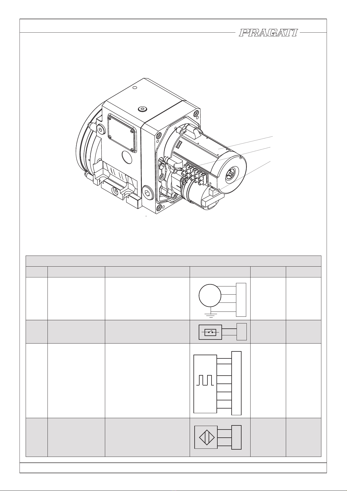
3.4 Details of Electrical Connections
1. Torque Motor 2.Thermal switch 3. Absolute Encoder 4. Proximity Switch
1
2
3
4
5
6
7
8
9
10
11
3 ~
U
V
W
E
T
T
Wiring Details For Bi-Directional Tool Turret
Sl.No Component NumberCharacteristics Details Wire size
1Torque motor
Alternative voltage
Alternative frequency
Phase3CAV022DNA083,514
zH06DNAzH05
Motor short circuit power
0.9 kVA
²mm57.0
2Thermal switch 415V AC 2A°011
Normally closed contact
²mm2.0
3Absolute encoder
DC Ripple 10%V03-51
DC Ripple 10%V03-01
Supply)(Am053
Channel (Load)/Am05
Output-PNP
Output-PNP-No
²mm2.0
4
Proximity switch
(Turret clamp
Signal)
Load)(Am002 ²mm2.0
R-phase
Y-phase
B-phase
Earthing
Bit 1
Bit 2
Bit 3
Bit 4
Strobe
Parity
0 V
24V DC
Out Put
0 V
24V DC
IMB50052014
Fig 3.4
1(2)
4
3

BI-DIRECTIONAL TOOL TURRET 11
3.4.1 Electrical motor wiring details
MF MR SSR1 SSR2
MF
MR
0V
0V
24V DC
TC
E
Supply
T1
M M M
MR
TC
TC
MF
TC
Q 4.0 Q 4.1
I 3.2
Output
Programable controller (PLC)
MOTOR
3 ~
MPCB
Set @ --- 0.6A
R
Y
B
N
E
Torque motor
Forward Reverse Solid state
Relays
Thermal relay
110°C
Normally closed
415V AC 2A
SSR
415V AC 25A
Fig 3.5
The figure shows recommended wiring diagram Turret.
Please note that only 3 phase motor with thermal relay is part of
Turret supply.
1. Solid state relays are required to switch off the motor in shortest
possible time
2. Thermal relay should directly switch off the motor.
IMB50052014
Use fuse rating about three times motor
Current. (minimum 6a fuse to be used)
Motor current (Amps)
/514
083 220 101
Current(A)
Voltage
1.2 2.6 3.3
BI-DIRECTIONAL TOOL TURRET 12
1
0
1
0
1
0
1
0
1
0
1
0
1
0
Bit 1
Bit 2
Bit 3
STROBE
PARITY
T1T 2
1
0
1
0° 180° 360° 360°
180°
POSITION 4 POSITION 5
TURRET CLAMP
POSITION 3
START
T3
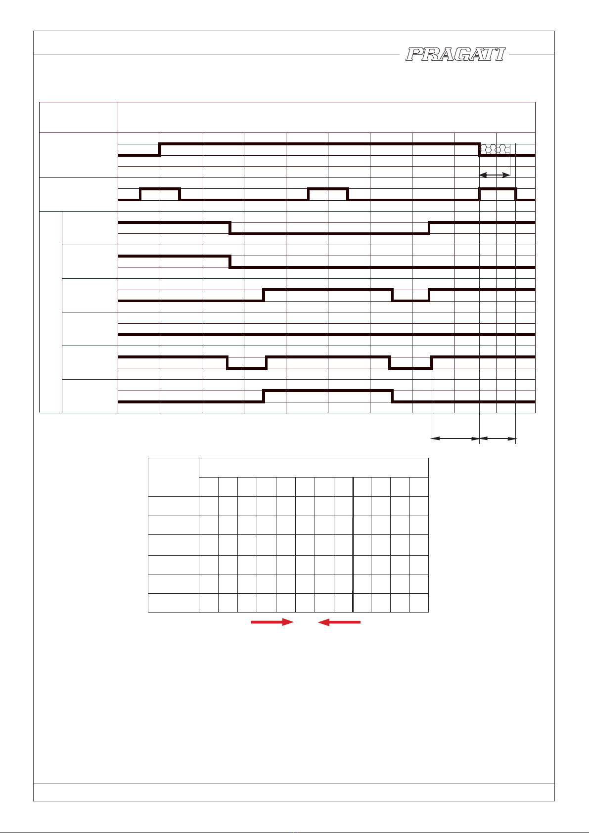
Following points should be noted while selecting control system for turret :
1. Direction of rotation of motor for shortest indexing time is to be decided by control system.
2. Indexing times of these turrets are short. It is necessary to select particularly fast PLC (programmable logic
controller) for the control of turret operations.
3. Referring to the signal diagram, value of T3 is particularly critical. Motor must come to a physical halt within
this time. Otherwise, the turret will get de-clamped and the Turret clamp signal will be lost.
Following measures are suggested for stopping the motor in minimum possible time:
a. Control should be capable of detecting the Turret clamp signal within 3 to 6 ms.
b. Solid state relays should be incorporated in the motor circuit to ensure fastest possible disconnection.
Regular contactors can be used for motor direction selection, followed by solid state relays, at least in
two phases.
CAM ANGLE
MOTOR
TURRET
CLAMP
SIGNAL
Bit 4
ENCODER
ENCODER SIGNALS
CW
CCW
POSITION NUMBER
Bit 1 1 0 1 0 1 0 1 0 1 0 1 0
Bit 2 0 1 1 0 0 1 1 0 0 1 1 0
Bit 3 0 0 0 1 1 1 1 0 0 0 0 1
Bit 4 0 0 0 0 0 0 0 1 1 1 1 1
STROBE 1 1 1 1 1 1 1 1 1 1 1 1
PARITY 1 1 0 1 0 0 1 1 0 0 1 0
Fig 4.0
1 2 3 4 5 6 7 8 9 10 11 12
110ms 125ms
4. TURRET CONTROL
4.1 Electrical signals
IMB50052014

BI-DIRECTIONAL TOOL TURRET 13
4.2 Flow chart for turret control
Fig 4.1
‘TIME FAULT’
YES
YES
YES
T4> 4SEC
D
D
END
CYCLE COMPLETE
TURRET CLAMP TURRET NOT
POSITION FAULT
DELAY T5=T3+5 msec
ALARM
LOCKED ALARM
SWITCH ON?
SIGNAL
NO
NO
NO
DELAY T5 msec
STOP MOTOR
YES
YES
YES
YES
YES
YES
YES
YES
START TORQUE
MOTOR ‘CW’
START TORQUE
MOTOR ‘CCW’
YES
TURRET CLAMP
SWITCH
ON
NO
NO
NO
NO
NO
NO
NO
(Y-X)<N/2 (X-Y)<N/2
X<Y
D
D
B
B
TURRET CLAMP
SWITCH
OFF?
“N”=NUMBER OF INDEX POSITION 8, 12, 24
START
POSITION ‘X’
POSITION ‘Y’
DEMAND
DEMAND ALARM INVALID
TOOL DEMAND
VALID?
1< Y < N
E
E
A
A
START 4 SEC
TIMER T4
X=Y
X=Y
X=Y
E
E
ALARM
Note : Monitor turret clamp switch signal on continuous basis generate feed -hold. If clamp signal missing
IMB50052014

BI-DIRECTIONAL TOOL TURRET 14
4.3. Requirements of turret control :
4.3.1 Sequence of operation :
Flow chart on the page 13 gives the details of operation sequence. Following general points should be
noted while selecting the control system and its program.
4.3.2 control system :
* Select a particularly fast PLC (programmable logic controller) for the control of turret operation.
* Control should be capable of detecting the turret clamp switch signal within a period 5 ms.
* Motor should be switched off by solid state relays. Contactors take much longer time (30 to 40 ms).
Suggested electrical circuit is on page 12.
4.3.3 Safety interlocks :
A. 'Motor Overheat' signal
Thermal Switch has been provided in the motor winding to give indication of motor overheating. In the event of
overheating relay should trip the motor contactor, and also give ‘Motor overheating’ signal to the control circuit.
Motor contactor should be tripped without depending on PLC software.Typical circuit diagram is given in page
12.
B. 'Time Fault'’signal
Time required for indexing through 180° is between 1.3 seconds to 3.1 seconds depending on the Turret model.
This is the maximum time required for completing the indexing operation. If the ‘cycle complete’ signal is not
received even after this time, this will be an indication of some fault in the indexing cycle. Control circuit should
be programmed to give a ‘Time Fault’ signal, if the ‘Cycle complete’ signal is not received within a specified time
(say 1 second more than the maximum expected time) after the ‘Cycle Start’ signal.
C. 'Turret Not Locked' signal
Turret clamp signal should be continuously monitored. If the clamp signal is missing, a Feed Hold signal should
be generated to stop the machine movements. Simultaneously, ‘Turret not Clamped’ alarm signal should also
be generated.
D. 'Position Fault' signal
At the end of indexing cycle, a check should be made to ensure that the turret has indexed to the demanded
position. If the actual position and demanded position do not match, then ‘Position fault’ alarm should be
generated.
E. 'Invalid Demand' signal
An eight position turret cannot react to a tool demand other than 1 to 8. If any other tool position (say 12) is
demanded, the control should give ' INVALID DEMAND ' Message.
All these signals should stop the operation of the machine, and an indication should be available on the control
panel regarding the nature of the fault.
F. Manual mode of turret control
Control panel should have a facility to change over the turret control to manual mode. Following facilities should
be available in this mode :
G. ’Inching’ the motor in either direction :
During servicing, it is sometimes necessary to rotate the motor for checking the functioning of the turret mecha-
nism. Push button switches should be provided to allow ‘inching’ of the motor in either direction.
H. Tool indexing cycle on manual demand :
Control system should provide a facility to index the turret into desired position by manual data entry of ‘tool
demand’. This can be either by a ‘thumb wheel’ switch, or by push button data entry through CNC panel.
Indexing cycle through manual tool demand will be identical to the normal indexing cycle, except for the fact the
cycle will start even if initial signal conditions are not satisfied.
Turret can stop in an un-clamped position, if the power fails during the indexing cycle. It is then possible that
valid encoder feedback is not available because the turret has stopped in an intermediate position. In such a
case, in MDI mode, the control should choose a fixed direction of motor rotation (i.e. default direction) and then
index the turret to demanded position.
IMB50052014

BI-DIRECTIONAL TOOL TURRET 15
5. MAINTENANCE
5.1 Lubrication
Turret is lubricated by medium viscosity gear box oil. Normally, oil does not require regular attention.
Oil should be changed in case the turret is opened for some reason. Use only acid- free gear box oil
HLP ISO VG 46. Place the turret on the horizontal base, And fill the oil to the level seen in oil level
indicator (109). The oil filling capacity is 0.5 liters.
Turret can be indexed by cranking the rotor of electric motor by hand. Hand cranking is required for inspecting the
setting of encoder, proximity switch and clamping function of disc springs. If turret is hand cranked through one
indexing cycle; the extra pressure can be felt during the clamping phase.
Procedure for hand cranking is as follows :
1. Switch off power supply to the motor.
2. Remove Back cover. Hexagon head(A/F 10) of motor shaft is now approachable.
3. Use a suitable spanner to crank the motor.
5.2 Hand cranking :
Fig 5.2
Box spanner
A/F 10 for cranking
Back
cover
Fig 5.1
Drain plug (110)
Oil filling plug
Grade EP-140
Viscosity @40deg:370 CST
(106)
Oil level indicator
(109)
IMB50052014

BI-DIRECTIONAL TOOL TURRET 16
5.3.1 Procedure for adjustment of Ringfeder clamps.
Allen Key
A/F 5
Holes drilled
in flange
65
5.3 Adjustment of Ringfeder Clamps
Accident can happen while the turret is indexing Spurious signals in control circuit can unintentionally start the
indexing cycle, causing the turret to index in the middle of a machining operation.
In such accidents, the friction joint of Ringfeder slips and protects the internal mechanism from damage. Such
a condition is usually associated with the change in angular position of tool disc in the clamped position or
excessive noise in one direction during indexing. So, it is necessary to put back the indexing mechanism into
proper orientation by adjustment of ringfeder clamps
* Drain lube oil
* Remove Encoder (02) and mounting flange (05)
* Bring the turret to the clamped position by hand cranking, bolts (65) in line with the holes drilled in flange
(10). In case of a 8 station turret, you may have to crank through one or two stations to get the alignment.
* Use suitable Allen key and loosen all bolts. Slightly tap the bolt heads to release Grip.
* Crank the turret by hand and bring the turret in declamped position.
* Fit the Tool disc on the flange and force the angular movement to loosen the grip of Ringfeder clamps.
* Bring the Tool disc in proper angular position. Crank the motor and bring the turret in clamped position.
* Tighten Bolt (65) to clamp Indexing gear (13) on the spindle. Bolts should be tightened in 3 or 4 stages.
Tighten opposite bolts in sequence 1,5,2,6,3,7,4,8.
* crank the motor by hand in both directions and check for correct indexing movement.
* Fit flange (05) and encoder (02) back in position follow encoder mounting instructions( sec 6.1 ).
Fig 5.3
64
58
59
57
12
11
10
54
13
IMB50052014

BI-DIRECTIONAL TOOL TURRET 17
Detail - A
Groove on periphery of encoder
Encoder and Drive dog Assembly
1. Mount the drive dog (69) on the encoder shaft by aligning the mark on the face with that on the dog (6.1a)
Ensure that turret is in work position, if not hand crank the motor and bring the turret in working postion.2.
3. Align the slot of the drive dog with Drive pin (59) on Main spindle and Position the Encoder on the Encoder
mounting flange (05) (Fig 6.1c).
4. Match the Encoder marks on its periphery with the marks of flange(02) on its face (detail C).
5. Clamp the Encoder in this position using Clamps and screws (03,04).
0304
026805 69
Fig 6.1a
Detail - C
Alignment of encoder
with flange
Groove
on encoder
mounting
Groove on
periphery
of encoder
Alignment of Groove on face of
encoder shaft with Drive dog
Detail - B
Groove
in line with
each othe
r
Fig 6.1C
A
02
63
B
Sectional view
Fig 6.1b
05
03
04 C
6. REPLACING COMPONENTS
6.1 Replacement of Rotary Encoder
IMB50052014

BI-DIRECTIONAL TOOL TURRET 18
6.2 Replacement of the proximity switch
* Bring the turret to clamped position by hand cranking.
* Take out Proximity switch assembly.
* Measure distance 'a' and note it down for reference.
* Replace switch, and maintain distance 'a'.
* It is important to maintain the gap of 0.8 mm to 1 mm as shown in the figure; Detail X. If necessary
adjust 'a' to get the desired gap.
* replace the 'O' Ring(114) back in position.
* Place the switch assembly back in position . Hand crank the Turret( ref page 15) and check the
function of the switch. Switch LED should light up during clamped position of turret.
Fig 6.2a
XX
XX
X
115
112
114
LED
113
24.5mm
GAP
0.8mm
Detail X
Proximity switch assembly
Fig 6.2b 118
115
59
01
IMB50052014

BI-DIRECTIONAL TOOL TURRET 19
6.3 Replacement of Coolant valve Button (poppet).
Fig 6.3d
Main Body
Coolant Ring
Coolant Flange
Marking groove in line with
coolant flange and Coolant Ring
Marker settings for working position
Insert suitable rod and use
it as a handle for the
adjustment of angular
position of Coolant ring
M4x40 for pulling
Coolant Poppet (44) rubs against coolant ring during indexing; and is liable to wear. Provision has been to
made replace the button, without removing the Tool disc from the turret.
For replacement , Loosen clamps (110), and move coolant ring to align the reference marks in line with the
corresponding mark on the body as shown in fig (fig 6.3f). Remove the Grub (47). Use M4x6 screw for removing
the poppet Assembly. Change the poppet and reassemble it.
Fig 6.3b
Fig 6.3a
IMB50052014
110
103
79,56
Fig 6.3c
Fig 6.3e
20°
20°
22 50
27
44
48
43
49
47
26 98

BI-DIRECTIONAL TOOL TURRET 20
7.0 ASSEMBLY DRAWINGS
With back cover and motor removed.
Actual orientation of axes is visible in this view.
Fig 7.2
Fig 7.1
OVER ALL ASSEMBLY
121
120
125
116
86
83
115
118
113
IMB50052014
Fig 7.1b
Fig 7.1a
111
110
101
108
109
99,100
117
Other manuals for BTP-50
1
Table of contents
Other Pragati Lathe manuals


Popular Lathe manuals by other brands


VEVOR
VEVOR HS001 instruction manual

Huvema
Huvema HU 360 VAC X 1000 Operation manual

Major Manufacturing
Major Manufacturing HIT-66-274 instructions

Rikon Power Tools
Rikon Power Tools 70-100 Operator's manual

Hafco Woodmaster
Hafco Woodmaster T-13B Operation manual

Rikon Power Tools
Rikon Power Tools 79-100VS owner's manual


