Diamond H2O Reliant DRS4-EM-15 User manual


pg. 1
Set Up Instructions for DRS4 Series Single Tank
Inspect the packaging of the equipment to confirm that nothing was
damaged during shipping. (Figure 1)
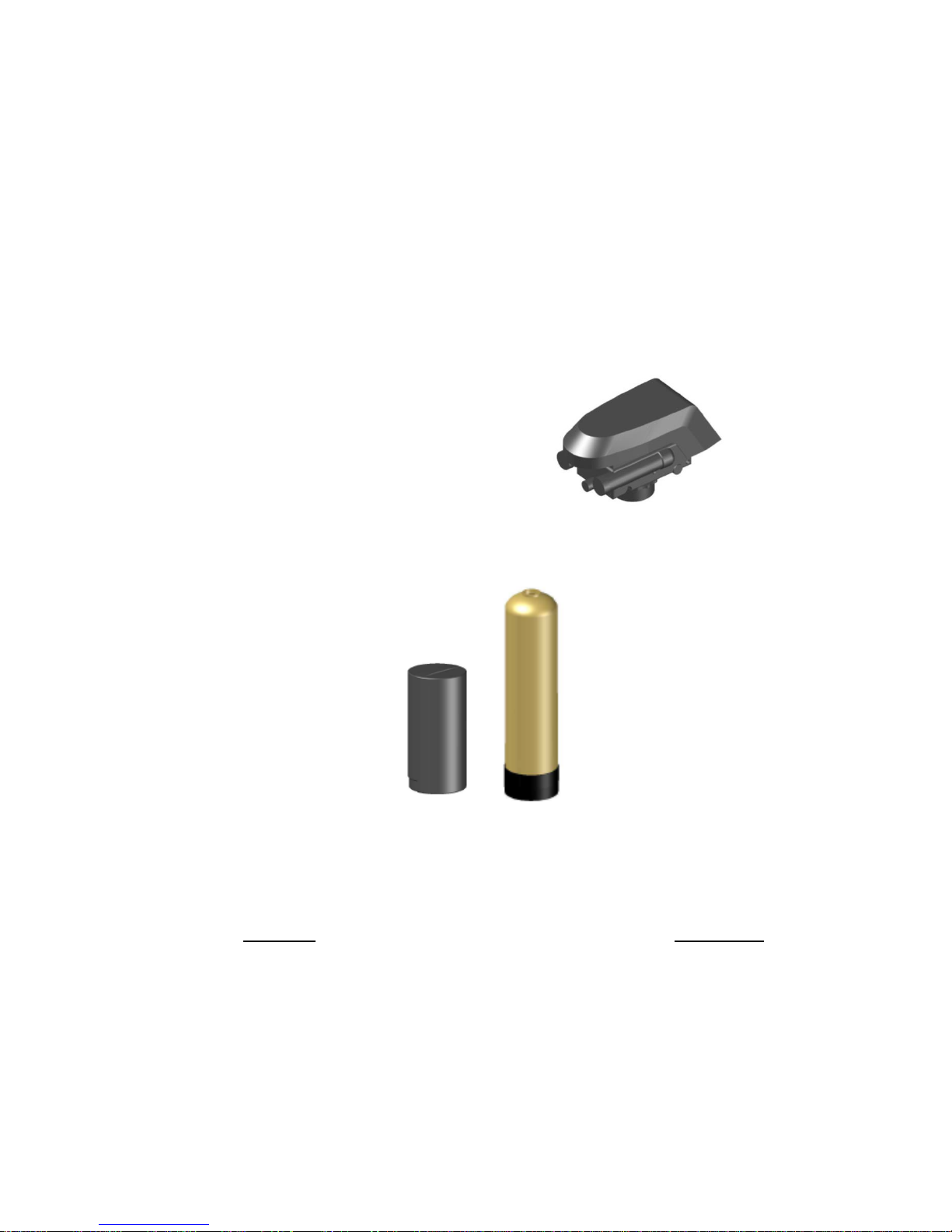
Remove the resin tank(s) and valve(s) from the packaging. Make sure
everything is included and without damage. Notice that the valve(s), Brine
Line ‘T’, brine line hose, and MAV valve will be found in the brine tank.
Below is a checklist with everything you should have received.
_____ 1) Control Valve
(Figure 2)
_____ 2) Brine Tank (Figure 4)
_____ 3) Brine Line Hose
_____ 4) Softener Tank (Figure 5)
_____ 5) Correct Amount of Resin (from Model and Media Requirements Table on page 2)
Call Diamond H2O right away if anything is missing. Contact the freight company immediately if
anything is damaged. Diamond H2O will not be liable for any damage received after shipping.
Packaged By: ___________________________________ Date: _______________
Received By: ___________________________________ Date: _______________
Figure 2: Control Valve
Figure 4:
Brine Tank
Figure 5:
Softener Tank

pg. 2
Contents
1. Obtain the required tools listed below:................................................................................................ 2
2. Place the tanks near a water source..................................................................................................... 3
3. Setting up the tank:............................................................................................................................... 3
4. Connect the brine tank. ........................................................................................................................ 4
5. Connect the Valves to the Water Source.............................................................................................. 5
6. Electrical............................................................................................................................................... 5
7. Start up the system for the first time. .................................................................................................. 6
8. Bypass Valve Operations....................................................................................................................... 6
9. Main Operating States .......................................................................................................................... 9
10. Program the Valve .......................................................................................................................... 10
11. Backwashing.................................................................................................................................... 13
12. Troubleshooting..............................................................................................................................14
13. System Specifications......................................................................................................................14
14. Error Codes ..................................................................................................................................... 15
Table 1: Media Requirements.
1. Obtain the required tools listed below:
A. Utility Knife
B. Pliers
C. Phillips Screwdriver
D. Hammer
Model Number
Amount of Resin per
Tank (cu. ft.)
DRS4-EM-15
0.5
DRS4-EM-24
0.75
DRS4-EM-32
1
DRS4-EM-33
1
DRS4-EM-49
1.5
DRS4-EM-66
2

pg. 3
2. Place the tanks near a water source.
A. Select a position near a floor drain that has adequate carrying capacity to handle the
backwash flow rate. Refer to the specification Table in Section 8 for the appropriate flow rate.
B. Place the softener(s) and brine tank on a level, firm foundation, like concrete.
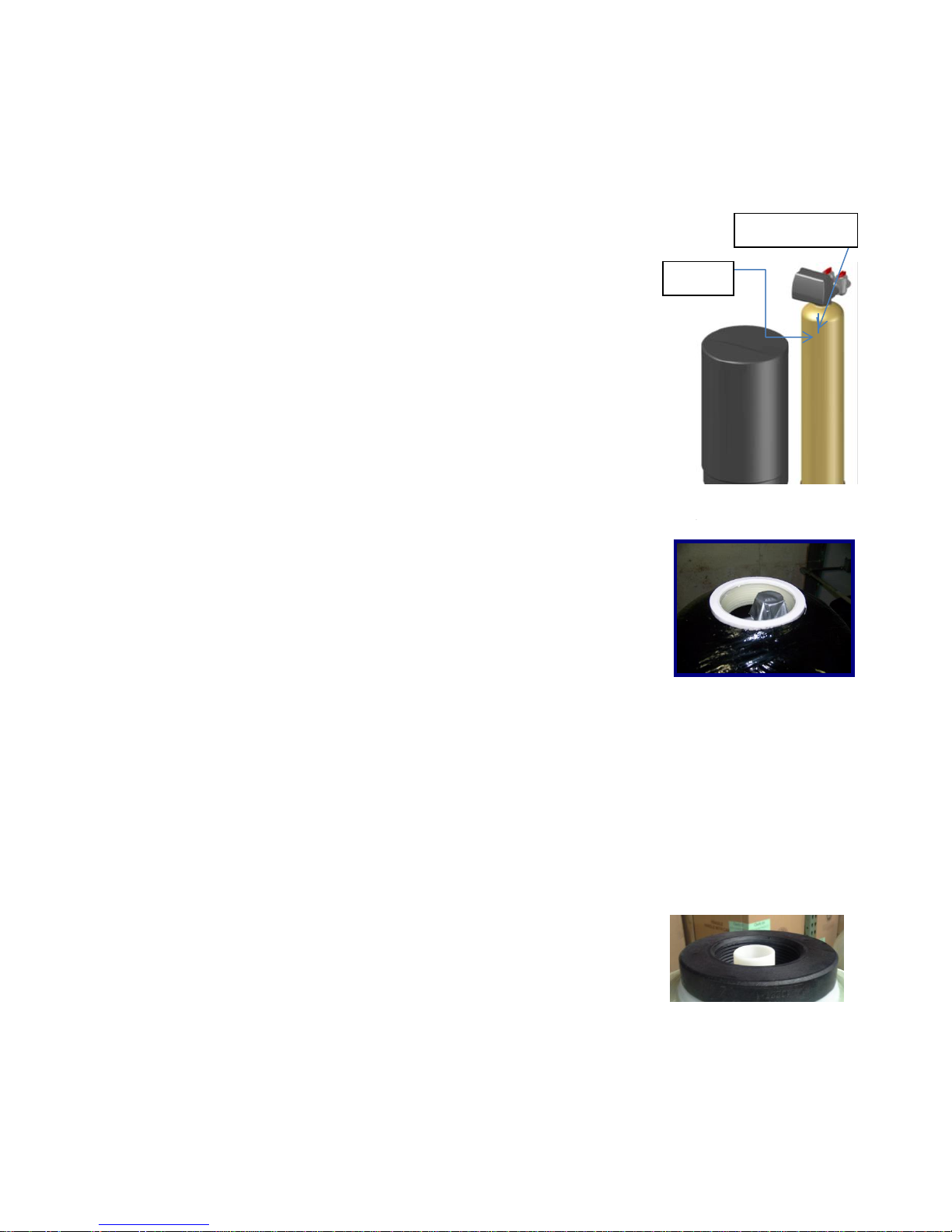
C. Determine the “front” of each tank received. For each tank:
a.Make sure that the distributer riser is flush with the top of
the resin tank.
b.Before placing any water, gravel, or resin in the resin tank,
screw in a control valve to the point where it is secure. The
valve does not need to be forced on, but should be snug.
c. The two tanks should be placed next to each other, with the
brine tank off to the side. The correct distance between the
two tanks can be determined by connecting the MAV to
both valve outlets.
d.Mark the “front” of each resin tank (shown in Figure 7) with
either a marker or tape. The front of the resin tank is
determined by the location of the face of the control valve
once it has been secured to the face of the control valve.
Make sure that the system is positioned in a way that the
plumbing can be installed.
D. Before Filling the Tanks:
e.Remove the valve(s)
f. Ensure that the front(s) of the tank(s) is/are positioned correctly. Once filled, the resin
tanks will be very difficult to move.
g.Cover the exposed end of the distributor riser(s) to make sure no resin gets inside. Covering
up the riser(s) with duct tape is one option, shown in Figure 8.
h.Obtain a funnel to assist placing the resin in the resin tanks. (A funnel designed specifically
for our resin tanks can be ordered from Diamond H2O Conditioning. The part numbers for
the two types of funnels are table 3.)
3. Setting up the tank:
A. Fill the tank up to 30% full of water.
B. Check the system specifications on page 2 to determine the correct amount of resin needed
for your system.
C. Position the distributor tube so it is in the center of the tank, shown in Figure 9. The
distributor tube should sit about an inch higher than the tank.
Figure 9: Centered Distributer Tube
Figure 8: How to Block
Distributer Tube
Mark w/ Tape
Front
Figure 7: Front of tank

pg. 4
D. SLOWLY, pour the correct amount of resin
into the tank. Again, try to keep the media
level by carefully rocking the tank back and
forth.
E. Fill the rest of the tank with water to prevent
air from getting in the tanks and potentially
losing media.
F. Verify that there is a large O-ring on the
control valve(s) adapter base.
G. Place the control valve on the tank, making
sure that the distributor tube fits into the
bottom of the control valve.
4. Tighten the control valve onto the tank to the
point that it is snug. Double check that the valve
is in a correct position to be able to install the
plumbing.
5. Connect the brine tank.
A. Remove the ties on the brine line hose (included in the brine tank).
B. Remove the well cap and connect one end of the brine line hose to
the brine line connection (Shown in Figure 11) of the brine tank.
Tighten the brine line hose to the brine line connection by turning
the cap of the brine line connection clockwise by hand. Make sure
that no air can get into the line, or the softener will not regenerate
properly.
C. Safely dispose of any leftover tubing.
D. Fill the brine tank with salt.
Distributer
Tube
Resin
Gravel
Distributer
Basket & Radials
Figure 10: Resin Tank Diagram
Figure 12: Brine Tank
Diagram
Figure 11: Brine Well Picture
Brine Line Connection
Well Cap

pg. 5
6. Connect the Valves to the Water Source
A. Pipe or tube a line from the Control Valve Drain (Figure 13) to the drain. Refer to section 9 for
the proper sized drain line.
DO NOT
install a valve in this line
use a pipe smaller than the valve sizes listed on section 9
make a direct connection to the drain
oProvide an air gap at least four times the diameter of the drain pipe to
conform to sanitation codes and be able to observe the drain flow.
use an excessive amount of elbows in the plumbing
B. Connect the facility plumbing to the control valve inlet following all local codes.
C. Temporarily run the control valve outlet to the drain.
Note: Make sure all piping is free of thread chips and other foreign matter.
7. Electrical
The Water Filter use requires single-phase 110 volt, 1 phase, 60 hertz, and 5 amp service; it is
equipped with a 10 foot electrical cord and a wall plug-in transformer.
NOTE: We recommend that a licensed electrician install your system in accordance
with local and national electrical codes.
WARNING: To reduce the risk of electrical shock, the incoming power supply must include a
protective earth ground.
NOTE: Some Filters are supplied with an optional micro-switch that closes during
Backwashing. The wires with connectors can be located coming out the back of
the control valve.
Figure 13: Control Valve Diagram
Drain Outlet
Valve Inlet
Valve Outlet

pg. 6
8. Start up the system for the first time.
A. Add about three gallons of water to the brine tank.
B. Make sure the tanks are filled with water.
a. Manually put the control valve into regeneration
(Hold the regen button)
b. A mixture of air and water will flow from the drain line.
c. Slowly open the bypass valve’s inlet to allow water to slowly enter the tank.
(shown in figure 14)
d. Once the tank is filled, only water will be coming out of the drain line. Put the system back
into bypass operation. Run each step of the regen cycle (Figure 20) for a few minutes.
C. Program the Valve. Most of the settings were pre-programed by Diamond H2O. The installer
must enter the installer settings shown in part 8 section C of this manual.
Figure 14: Opening
bypass valve’s inlet
Figure 15: DRS4 Diagram
Control Valve Outlet
Control Valve Inlet
Bypass Valve
Drain Outlet
Brine Line Inlet

pg. 7
9. Bypass Valve Operations
A. The controls of the bypass valve can be turned 90° resulting in four modes of operation.
“Treated”
Water Exits
Supply Water
Enters
Figure 16: Normal Operation
Supply Water
Enters
Supply Water
Exits
Figure 17: Bypass Operation
Supply Water
Enters
Supply Water
Exits
Figure 18: Diagnostic Mode
No Water
Exits
Supply Water is Shut
Off from the House
and the Valve.
Figure 19: Shut Off Mode

pg. 8
FEED FROM BRINE TANK
DRAIN
INLET
OUTLET
FEED FROM BRINE TANK
DRAIN
INLET
OUTLET
FEED FROM BRINE TANK
DRAIN
INLET
OUTLET
FEED FROM BRINE TANK
DRAIN
INLET
OUTLET
FEED FROM BRINE TANK
DRAIN
INLET
OUTLET
FEED FROM BRINE TANK
DRAIN
INLET
OUTLET
Service/Operation
Backwash:
Flow reversed to
flush debris from
resin bed to drain.
Regenerant Draw/ Slow
Rinse:
After one Tank’s Resin Bed is
exhausted, Regenerate is
drawn from Brine Tank
through Brine Line Valve to
Resin Bed. Hardness ions are
then replaced by sodium
ions, preparing Resin for
another treatment cycle. The
Regenerate flows through
resin (at a specific rate) to
exchange ions. Resin is now
‘Regenerated’ and ready for
another cycle.
Fast Rinse:
Removes any residual regenerant from
resin bed. (Water travels through the
resin bed and up the riser tube drain).
Regenerate Fill:
Water is sent to the
Brine Tank to create
regenerant for next
regeneration cycle.
Second Backwash:
Flow reversed to flush
debris from resin bed to
drain.
Figure 20: General Softener Operations
Key:
Hard Water
Soft Water
Salinized Water
Resin

pg. 9
10. Main Operating States
Figure 21 shows the main operating states for the software and how they interact.
Power
On
Reset
Self
Test System
Setup
In Service
Regenerating
Standby
Power
Program
and Data
Display
Find
Home
Figure 21: 762 State Diagram
A. Power On Reset
This will monitor the AC input to determine if the control is operating on 50 or 60 hertz power.
Function will pass to the self-test routine if the set key is pressed. The routine initializes all ports
and time bases. It reads data from the information memory and checks the validity of the data.
The control will set a flag indicating the time of day needs to be set.
B. Self-Test
The self-test routine will enter from and return to the power on reset routine. The self-test
routine will test all inputs and outputs. A simple test fixture will be used to connect to the
outputs and inputs.
C. Standby Power
The standby power routine is called anytime the unregulated voltage falls to a level indicating
that AC power has been lost. The microcontroller is placed in a sleep mode waking to maintain
the current time of day. Power to operate the microcontroller is supplied by a super capacitor.
The display will show the programmed valve number when it wakes from standby power.
D. System Setup
The initial programming routine is used to load a set of programmable variables based on the
resin volume in the softener. The system setup is a two-step process. First the valve is selected,
and then the resin volume is selected. The system setup routine is normally entered from the

pg. 10
power on reset routine if the initial setting (resin volume) is “no setting”. The initial setting can
be cleared in the Program and Data Display State.
E. Program and Data Display
The program and data display state consists of several routines that allow for setting and
displaying programmable values.
F. In Service
The in service state uses several routines that handle the monitoring and display function while
the valve is in service.
G. Regenerating
The regenerating routine handles the operation of the motor to position the cam in various
positions as needed to perform regeneration of the resin bed.
11. Program the Valve
All of the parameters on the valve can be displayed on the LCD Display. Use the Down Key and
Up Keys to navigate through the parameters. Each parameter can be edited by pressing the
Set Key. After the value has been changed, the value can be saved by pressing the Set Key
again. Most of the parameters have already been set by Diamond H2O. All of the parameters
are shown in Table 2, 3 and 4.
Figure 18: Key Pad and LCD Display
Set Key
Down Key
Up Key
Regeneration Key
LCD Display

pg. 11
Table 3: Level I Programming
Parameter
Description
Range of
Values
Minimum
Increment
Default
Units of
Measure
Notes
P1
Time of Day
1:00 - 12:59
AM or PM
0:00 - 23:59
1 minute
12:00
PM
hour
minute
Range depends on value
selected for P10
P2
Day of Week
N/A
1 day
None
N/A
Uses arrows under days of week
on overlay.
P3
Time of
Regeneration
1:00 - 12:59
AM or PM
0:00 - 23:59
1 minute
2:00
AM
hour
minute
Range depends on value
selected for P10

pg. 12
Table 3: Level I Programming (2).
Parameter
Description
Range of
Values
Minimum
Increment
Default
Units of
Measure
Notes
P4
Set Calendar
Override
0-99
1
0
days
0 = no calendar override,
0.5 = regeneration twice a day
at time of regeneration and 12
hours later.
Calendar Override skipped if at
least one Day of Regeneration
selected. Can be locked out of
changes in Level I programming.
P6
Set Amount of
Regenerant
S, H, L
N/A
S
N/A
S –Standard (9lbs/ft3resin)
H –High (15lbs/ft3resin)
L –Low (3lbs/ft3resin)
Lower salt settings are more
efficient, but will regenerate
more often.
P7
Estimated
Capacity
N/A
N/A
kg
Cannot be changed
Displays calculated capacity
(based on volume of resin used)
P8
Hardness
0-99
1
25
Grains per
gallon
Sets Water hardness level
This value is used to calculate
estimated capacity

pg. 13
Table 4: Level II Programming.
Parameter
Description
Range of
Values
Minimum
Increment
Default
Units of
Measure
Notes
P9
Units of
measure
0-1
1
0
0 = US 1 = Metric.
P1
0
Clock mode
0-1
1
0
0 = 12 hour clock 1 = 24 hour
clock.

PARTS AND ACCESSORIES
RELIANT Valve Exploded View
1
2
3
4
5
6
7
8
9
11
12
14
15
16
10
18A*
20
21
17
19
13
18B
*Warning: Do not use flow control ball with #18A.
22
22
23
pg. 14

RELIANT VALVE PARTS LIST
Code Part # Description Qty
1N.A. Reliant Valve Assembly 1
217-0100-XX Reliant Tank Adapter New Style 1
335-0063-RB O-Ring, Tank Adapter 1
5N.A. Top Plate, Reliant Valve 1
6105-0015-XX Spring, One Piece, Reliant Valve 1
773-0031-XX Cover, Reliant Valve 1
812-0069-XX O-Ring Group: Valve Body 1
912-0043-XX O-Ring Group: Meter Block 1
10 37-0072-RB 13/16 Rubber Insert (Optional) 1
11 129-0001-XX Locking Bar 1
12 55-0050-XX Cam, Reliant Standard, Black 1
13 82-0015-XX Motor/Optical Cable Assembly 1
14 60-0005-XX Screen/Cap Assembly 1
15 Injector Assembly 1
60-0007-XX "G" Injector - Tan (8" Tank)
60-0008-XX "H" Injector - Lt. Purple (9" Tank)
60-0116-XX "J" Injector - Lt. Blue (10" Tank)
60-0115-XX "K" Injector - Pink (12" Tank)
60-0023-XX "L" Injector - Orange (13" Tank)
16 31-0007-XX Injector Cap 1
17 Drain Line Flow Control Assy. 1
16-0016-XX No. 7 (1.3 gpm)
16-0017-XX No. 8 (1.7 gpm)
16-0018-XX No. 9 (2.2 gpm)
16-0019-XX No. 10 (2.7 gpm)
16-0020-XX No. 12 (3.9 gpm)
16-0021-XX No. 13 (4.5 gpm)
16-0009-XX No. 14 (5.3 gpm)
18A 34-0086-XX Regenerant Refill Control .33 gpm 1
18B 34-0187-XX Regenerant Refill Controller 1
19 44-0001-XX Air Check Kit 3/8" Male 1
20 N.A. Module, Sensor, Photo Interrupter 1
21 82-0021-XX Motor w/spacer, Pinion & Cable 1
22 16-0072-XX Flow Control Ball 1
23 58-0003-XX Turbine Cable 1
*12-0075-XX Valve Disc Kit 1
*17-0066-XX New to Old Aircheck Adapter
*12-0072-XX Kit, Meter Adapter 1
*67-0005-PL Bypass Assembly w/Install Kit 1
*12-0033-XX Bypass Installation Kit
*12-0022-XX 3/4" Copper Tube Adapter Kit 1
*12-0023-XX 1" Copper Tube Adapter Kit 1
*17-0027-CP 3/4" CPVC Tube Adapter Kit 1
*42-0019-CP 1" CPVC Tube Adapter Kit 1
pg. 15

pg. 16
12. Troubleshooting
A. Manual Backwashing
Delayed Manual Backwash
A delayed manual regeneration is programmed by pressing the REGENERATION key. The
regeneration icon on the LCD will flash indicating regeneration will start when the time of day
reaches the programmed time of regeneration. Pressing the REGENERATION key again will
turn off the regeneration icon and cancel the delayed regeneration.
Immediate Manual Backwash
An immediate manual regeneration is programmed by pressing and holding the
REGENERATION key for three seconds. The regeneration icon on the LCD will turn on. The
control will go to the regenerating mode.
Delayed Second Backwash
A delayed second regeneration is programmed by pressing the REGENERATION key while the
control is in the regenerating mode. The x2 icon next to the regeneration icon will flash
indicating a second regeneration will start when the time of day reaches the programmed
time of regeneration.
Double Immediate Manual Backwash
Back to Back manual regenerations are programmed by pressing and holding the
REGENERATION key for three seconds while the control is in the regenerating mode. The x2
icon next to the regeneration icon will turn on indicating a second manual regeneration will
start immediately after current regeneration is complete.
B. Power Loss
Only the current time of day will need to be reset if power is lost for greater than 8 hours. If
power is lost while the system is regenerating, the control will complete regeneration at the
point of interruption once power is restored.
13. System Specifications
Table 6: System Specifications
MODEL
CAPACITY & SALT per
REGENERATION
SERVICE FLOW
RATE (GPM) @ PSI DROP
SOFTENER
TANK(S)
BRINE TANK
(With Grid)
PLUMBING
MAXIMUM
MINIMUM
DIMEN’s
CAPACITY
DIMEN’s
CAPACITY
SERVICE
DRAIN
Capacity
Salt/Regen
Capacity
Salt/Regen
Dia x Ht (in)
Cu Ft
Dia x Ht (in)
Lbs.
Inches
Inches
BW flow
(gpm)
DRS4-EM-15
15,300
7.0 lb
9,600
2.5 lb
4.0 @ 5
7 x 35
0.5
18 x 33
300
¾, 1, 1 ¼
½
1.2
DRS4-EM-24
24,600
10.5 lb
15,500
3.8 lb
6.0 @ 9
8 x 44
0.75
18 x 33
300
¾, 1, 1 ¼
½
1.6
DRS4-EM-32
32,800
14.0 lb
20,700
5.0 lb
10.0 @ 15
9 x 48
1
18 x 33
300
¾, 1, 1 ¼
½
2.0
DRS4-EM-33
32,800
14.0 lb
20,700
5.0 lb
5.7 @ 6
10 x 54
1.5
18 x 33
300
¾, 1, 1 ¼
½
2.5
DRS4-EM-49
49,100
21.0 lb
31,000
7.5 lb
9.6 @ 15
12 x 52
2
18 x 40
400
¾, 1, 1 ¼
½
2.5
DRS4-EM-66
65,500
28.0 lb
41,400
10.0 lb
11.2 @ 15
13 x 54
2.5
18 x 40
400
¾, 1, 1 ¼
½
3.5

pg. 17
14. Error Codes
Problem
Possible Cause
Solution
E1, Err-1001, Err-101
=Control unable to
sense motor
movement
Motor not inserted full
to engage pinion, motor
wires broken or
disconnected
Disconnect power, make sure motor is fully engaged, check
for broken wires, and make sure two-pin connector on
motor is connected to the two pin connection on the PC
board labeled MOTOR. Press NEXT and REGEN buttons for
3 seconds to resynchronize software with piston position or
disconnect power supply from PC board for 5 seconds and
then reconnect.
PC board not properly
snapped into drive
bracket
Properly snap PC board into drive bracket and then press
NEXT and REGEN buttons for 3 seconds to resynchronize
software with piston position or disconnect power supply
from PC board for 5 seconds and then reconnect.
Missing reduction gears
Replace missing gears
E2, Err-1002, Err-102
=Control valve
motor ran too short
and was unable to
find the next cycle
position and stalled
Foreign material is
lodged in control valve
Open up control valve and pull out piston assembly and
seal/stack assembly for inspection. Press NEXT and REGEN
buttons for 3 seconds to resynchronize software with
piston position or disconnect power supply from PC board
for 5 seconds and then reconnect.
Mechanical binding
Check piston assembly and seal/stack assembly, check
reduction gears, check drive bracket and main drive gear
interface. Press NEXT and REGEN buttons for 3 seconds to
resynchronize software with piston position or disconnect
power supply from PC board for 5 seconds and then
reconnect.
Main drive gear too
tight
Loosen main drive gear. Press NEXT and REGEN buttons for
3 seconds to resynchronize software with piston position or
disconnect power supply from PC board for 5 seconds and
then reconnect.
Improper voltage being
delivered to PC board
Verify that proper voltage is being supplied. Press NEXT and
REGEN buttons for 3 seconds to resynchronize software
with piston position or disconnect power supply from PC
board for 5 seconds and then reconnect.

pg. 18
Error Codes Cont…
Problem
Possible Cause
Solution
E3, Err-1003, Err-103 =
Control valve motor ran too
long and was unable to find
the next cycle position and
stalled
Motor failure during a
regeneration
Check motor connections. Press NEXT and
REGEN buttons for 3 seconds to resynchronize
software with piston position or disconnect
power supply from PC board for 5 seconds and
then reconnect.
Foreign material built up
on piston and stack
assemblies creating
friction and drag enough
to time out motor
Replace piston and seal/stack assemblies. Press
NEXT and REGEN buttons for 3 seconds to
resynchronize software with piston position or
disconnect power supply from PC board for 5
seconds and then reconnect.
Drive bracket not snapped
in properly that reduction
gears and drive gear do
not interface
Snap drive bracket in properly. Press NEXT and
REGEN buttons for 3 seconds to resynchronize
software with piston position or disconnect
power supply from PC board for 5 seconds and
then reconnect.
E4, Err-1004, Err-104 =
Control valve motor ran too
long and timed out trying to
reach home position
Drive bracket not snapped
in properly that reduction
gears and drive gear do
not interface
Snap drive bracket in properly. Press NEXT and
REGEN buttons for 3 seconds to resynchronize
software with piston position or disconnect
power supply from PC board for 5 seconds and
then reconnect.
This manual suits for next models
5
Table of contents
Popular Water Dispenser manuals by other brands

GE
GE SmartWater GXSF18G Owner's Manual & Installation Instructions

Grunbeck
Grunbeck Delta-p Operation manual

BWT
BWT AQA drink Pro 20 CAS Installation and instruction manual

GE
GE GXSF30V02 Owner's manual and installation instructions

BRIO
BRIO CLPOU320BUVF4P Setup manual

Spectrum
Spectrum SWS Series Installation, service & operation manual

Elkay
Elkay EFA25 3C Series Installation, care & use manual

vitapur
vitapur VWD5446BLS Use & care guide

Water Right
Water Right ISP1-1044 Installation instructions & owner's manual

Miura
Miura MS Series installation manual

Culligan
Culligan 915 Use and care guide

DS Services of America
DS Services of America Pure Water Dispenser 200 Series How to Clean