Diamond Products CC3538JK Series User manual

CORE CUT
OPERATO
R
’S MANUAL
CC3538JK
(Electronic Fuel Injection)
May 2020
Rev.: 20-00 Part #: 1802723


TABLE OF CONTENTS
Table of Contents
Introduction ............................................................................................................................................. 6
CC3538JK Controls ................................................................................................................................ 7
CC3538JK Dimensions ........................................................................................................................... 8
CC3538JK Specifications ....................................................................................................................... 9
Safety ................................................................................................................................................... 10
Safety Alerts ...................................................................................................................................... 10
Proposition 65 ................................................................................................................................... 10
Respiratory Hazards ......................................................................................................................... 10
General Safety .................................................................................................................................. 11
Battery and Electrical Safety ............................................................................................................. 12
Blade Safety ...................................................................................................................................... 12
Blade Guard Safety ........................................................................................................................... 12
Cutting Safety .................................................................................................................................... 13
Hydraulic Safety ................................................................................................................................ 13
Belt Safety ......................................................................................................................................... 13
Transporting Safety ........................................................................................................................... 14
Lifting Safety ..................................................................................................................................... 14
Operating .............................................................................................................................................. 15
General Operating Precautions ......................................................................................................... 15
Handlebars ........................................................................................................................................ 15
Adjusting the Handlebars .............................................................................................................. 15
Control Grip Pushbuttons .................................................................................................................. 15
Blade Lowering Speed (Optional) ..................................................................................................... 16
Spotlight (Optional) ........................................................................................................................... 16
Fuel System ...................................................................................................................................... 16
Adding Fuel ................................................................................................................................... 16
Blade Guard ...................................................................................................................................... 16
Installing the Blade Guard ............................................................................................................. 17
Removing the Blade Guard ........................................................................................................... 17
Flange Guard .................................................................................................................................... 17
Installing the Flange Guard ........................................................................................................... 17
Removing the Flange Guard ......................................................................................................... 17
Diamond Blades ................................................................................................................................ 17
Inspecting the Blade ...................................................................................................................... 17
Blade Speed .................................................................................................................................. 18
Wrench .......................................................................................................................................... 18
Installing the Blade ........................................................................................................................ 18
Removing the Blade ...................................................................................................................... 19
Engine ............................................................................................................................................... 19
Vernier Throttle .............................................................................................................................. 20
Tasks Prior to Starting the Engine ................................................................................................. 20
Starting the Engine ........................................................................................................................ 20
Stopping the Engine ...................................................................................................................... 20
Transmission Lever ........................................................................................................................... 20
Engaging the Transmission ........................................................................................................... 21
Disengaging the Transmission ...................................................................................................... 21
Speed Control Lever ......................................................................................................................... 21
Water Supply ..................................................................................................................................... 21
Using the Water Supply ................................................................................................................. 21

TABLE OF CONTENTS
Water Pressure Switch (Optional) ................................................................................................. 22
Water Pump (Optional) .................................................................................................................. 22
Cutting Guides .................................................................................................................................. 22
Adjusting the Front Pointer ............................................................................................................ 22
Adjusting the Rear Pointer(s) ........................................................................................................ 22
Concrete Cutting ............................................................................................................................... 22
Helpful Hints Prior to Cutting ......................................................................................................... 23
Tasks Prior to Cutting .................................................................................................................... 23
Making a Cut ................................................................................................................................. 23
Making a Cut Using the Blade Depth Stop .................................................................................... 24
Continuing a Partial-Cut ................................................................................................................ 24
Finishing a Cut ............................................................................................................................... 24
Parking Brake (Optional) ................................................................................................................... 24
Engaging the Parking Brake .......................................................................................................... 24
Disengaging the Parking Brake ..................................................................................................... 24
Maintenance ......................................................................................................................................... 25
General ............................................................................................................................................. 25
Pre Maintenance Preparations .......................................................................................................... 25
Rear Cover Screen ........................................................................................................................... 25
General Cleaning .............................................................................................................................. 25
Cleaning Techniques ..................................................................................................................... 25
Engine ........................................................................................................................................... 25
Part Lubrication ................................................................................................................................. 26
Post Cleaning .................................................................................................................................... 26
Service Schedule .................................................................................................................................. 27
Daily Service ......................................................................................................................................... 28
Check Engine Oil Level ..................................................................................................................... 28
Check Fuel Level ............................................................................................................................... 28
Hydraulic System .............................................................................................................................. 28
Adding Fluid to the Hydraulic Lift Pump ........................................................................................ 29
Lubricate the Blade Shaft Bearings ................................................................................................... 29
Belt System ....................................................................................................................................... 29
Tensioning the Drive Belts............................................................................................................. 30
Tensioning the Jackshaft Belts ...................................................................................................... 30
100 Hour Service .................................................................................................................................. 31
Bearing Lubrication ........................................................................................................................... 31
Lubricate the Jackshaft Bearings .................................................................................................. 31
Lubricate the Front Axle Bearings ................................................................................................. 32
Lubricate the Rear Axle Bearings .................................................................................................. 32
Lubricate the Transmission Jackshaft Bearings ............................................................................ 32
Lubricate the Linkage Assembly .................................................................................................... 32
Lubricate the Front Wheels ........................................................................................................... 33
Replace Engine Oil and Filter ........................................................................................................... 33
150 Hour Service .................................................................................................................................. 34
Clean the Air Cleaner Filter Element ................................................................................................. 34
Replace the Fuel Filter ...................................................................................................................... 35
300 Hour Service .................................................................................................................................. 35
Replace the Air Cleaner Filter Elements ........................................................................................... 35
Yearly Service....................................................................................................................................... 36
Replace and Gap Spark Plugs .......................................................................................................... 36

TABLE OF CONTENTS
Regular Maintenance ............................................................................................................................ 36
Drive Alignment ................................................................................................................................. 36
Wheels .............................................................................................................................................. 36
Replacing the Front Wheels .......................................................................................................... 37
Replacing the Rear Wheels ........................................................................................................... 37
Battery ............................................................................................................................................... 37
Battery Type .................................................................................................................................. 38
Servicing the Battery ..................................................................................................................... 38
Speed Control Lever ......................................................................................................................... 38
Adjusting the Speed Control Lever Linkage .................................................................................. 38
Adjusting the Speed Control Lever Friction ................................................................................... 38
Shaft Tachometer Magnetic Sensor (Optional) ................................................................................. 39
Adjusting the Magnetic Sensor ...................................................................................................... 39
Replacing the Magnetic Sensor ..................................................................................................... 39
Transmission ..................................................................................................................................... 39
Cooling Fan ................................................................................................................................... 39
Tightening the Rear Drive Chain ................................................................................................... 39
Belt Replacement .............................................................................................................................. 40
Replacing the Blade Drive Belts .................................................................................................... 40
Replacing the Jackshaft Belts ....................................................................................................... 41
Replacing the Transmission Drive Belt .......................................................................................... 41
Belt Sheaves ..................................................................................................................................... 41
Changing the Small and Large Jackshaft Sheaves (14” through 26” Saws) ................................. 41
Changing the Small Jackshaft Sheave (30” Saw), Blade Shaft Sheave, Transmission Sheave,
and Engine Sheave ....................................................................................................................... 42
Aligning the Belt Sheaves.............................................................................................................. 42
Engine ............................................................................................................................................... 42
Lifting ................................................................................................................................................. 42
Transporting ...................................................................................................................................... 42
Storing ............................................................................................................................................... 42
Disposal ............................................................................................................................................ 43
Appendix A ........................................................................................................................................... 44
Troubleshooting ................................................................................................................................ 44
Appendix B ........................................................................................................................................... 45
CC3538JK RPM Chart ...................................................................................................................... 45
CC3538JK Blade Size Conversion Charts ........................................................................................ 45
Appendix C ........................................................................................................................................... 46
Additional Resources ........................................................................................................................ 46
Appendix D ........................................................................................................................................... 50
Model and Serial Numbers ................................................................................................................ 50

INTRODUCTION
Introduction
Welcome to the Diamond Products family and thank you for choosing Diamond Products equipment.
At Diamond Products we are driven to ensure you are completely satisfied with your product and
continually strive to improve our product line so that we can offer you the best possible equipment in
the industry.
This operator’s manual is a critical document that provides pertinent information regarding the safety,
operation, maintenance, and care of your new equipment. Keep this manual available at all times.
Operate the equipment and all of its components according to this manual. Failure to comply with and
understand the following safety, operation and maintenance instructions can result in serious injuries
and/or death. All operators must be properly trained or supervised by experienced personnel prior to
using this saw and should understand the risks and hazards involved. Diamond Products discourages
improper or unintended equipment usage and cannot be held liable for any resulting damages.
Equipment modifications should be made by Diamond Products to ensure safety and design. Any
modifications made by the owner(s) are not the responsibility of Diamond Products and void all
equipment warranties if a problem arises as a result of the modification.
Refer to the Diamond Products Parts List for additional information and part diagrams. Refer to the
engine manufacturer as the primary source for all safety, operations, and maintenance instructions
regarding the engine. Prior to operating, record the saw’s serial number, and the engine’s model and
serial numbers in Appendix D.
6

INTRODUCTION
CC3538JK Controls
1. Handlebars – Allows for manual
maneuvering of the saw.
2. Handlebar Locking Knobs – Locks the
handlebars in place.
3. Water Hose Fitting – Connects to water
source hose or water supply hose.
4. Water Valve Lever – Controls water flow
to the blade.
5. Ignition Switch – Three position switch
stops the engine, provides power to
accessories, or stops the engine.
6. Check Engine Light – Illuminates when
there is an issue with the engine.
7. Vernier Throttle – Increases or decreases
engine speed.
8. Hour Meter – Gauge displays the engine’s
accumulated operational hours.
8A Blade Tachometer (Optional) – Indicates
blade speed in RPM.
9. Depth Stop Knob – Allows operator to set
the cutting depth and increase or decrease
the cutting depth.
10. Cutting Depth Indicator – Displays the
current depth of cut in inches.
11. Pointer Rope Cleat – Secures the front
pointer rope.
12. Water Pump Switch (Optional) – Activate
water pump.
13. Water Pressure Switch (Optional) –
Indicates low water pressure to the blade.
Note: The switch does not detect flow.
14. Spotlight Switch (Optional) – Activates
spotlight.
15. Emergency Stop Button – Stops the
engine.
16. Speed Control Lever – Provides forward,
reverse, and stop control.
17. Transmission Lever – Manually engages
and disengages the transmission.
18. Fuel Tank Cap – Fuel port; indicates fuel
level.
Items Not Shown Above:
19. Blade Lowering Speed Valve (Optional) –
Controls the lowering speed of the saw.
20. Parking Brake Lever (Optional) –
Engages or disengages the parking brake.
21. Spotlight (Optional) – Provides a working
area light source.
7

INTRODUCTION
CC3538JK Dimensions
CC3538JK Dimensions Inches Millimeters
A Saw Height 43 1092
B Saw Length - Min. 46-3/4 1187
C Saw Length - Max. 125-1/2 3188
D Handle Extension - Max. 28 711
E Frame Length 39-3/4 1010
F Wheel Base Length 18-1/4 464
G Saw Width 30-1/4 768
H Rear Frame Width 23-1/2 597
I Front Wheels Inside Width 20-1/4 514
J Rear Wheels Outside Width 22-1/2 572
K Inner Flange to Inner Flange Width 26-3/4 679
L Blade Raise Height - Max. 17 432
8

INTRODUCTION
CC3538JK Specifications
CC3538JK Specifications
Saw Model CC3538JK-14 CC3538JK-20 CC3538JK-26 CC3538JK-30
Blade Guard Capacity 14" (350mm) 20" (500mm) 26" (700mm) 30" (800mm)
Blade Cutting Depth Max 4.5" 7.5" 10.5" 12.5"
Blade Shaft Speed (1) 3000 rpm 2500 rpm 1900 rpm 1650 rpm
Blade Flange Size 5" OD 5" OD 5" OD 5" OD
Engine Model Kohler Command Pro ECH980
Rated Output Power 38 HP
Rated Speed 3600 rpm (Kohler rating)
Battery 12 Volt (630 CCA) group size 34
Saw Lift Pump Fluid Automatic Transmission Fluid (ATF); (2 Liter capacity)
Lubrication Type NLGI #2 Lithium grease
Blade Arbor Size 1" Diameter with drive pin
Blade Flange Style Quick disconnect
Blade Shaft Size 1-3/4" OD with left/right side blade mounting
Blade Shaft Bearings 2 Pillow blocks with spherical roller bearings
Jackshaft Drive
(Engine to Jackshaft) 6 V-Belts (3VX366) 6 V-Belts (3VX400)
Blade Shaft Drive
(Jackshaft to Blade Shaft) 6 V-Belts (3VX400)
Blade Coolant Dual stainless steel multi-jet spray tubes
Blade Guard Attachment Slip-on tapered spade
Blade Raise and Lower Electro-hydraulic power unit with push button control
Blade Lowering Speed Flow control valve (Optional)
Blade Depth Control Dial depth indicator and manual depth stop
Blade Alignment Telescoping front/rear left and right pointers
Axle Size (Front/Rear) Front: 1" OD straight / Rear: 1.25" OD straight
Front Wheels 6" x 2" with 1" poly tread (sealed roller bearings)
Rear Wheels 8" x 2-1/2" with 1-1/4" poly tread
Travel Speed 0-200 FPM (2.25 mph) forward/reverse
Rear Wheel Transmission Eaton Model 10 transmission with chain drive
Transmission Belt V-Belt (4L600W)
Rear Wheel Drive Gear drive
Parking Brake Manual rear wheel friction (optional)
Handle Bar Adjustment Variable extension with dual 0° and 30° angle range
(1) Theoretical speed, actual speed may vary.
9

SAFETY PRECAUTIONS
Safety
Operate the equipment and all of its
components according to this manual. Failure
to comply with and understand the following
safety, operation and maintenance instructions
can result in serious injuries and/or death. All
operators must be properly trained or
supervised by experienced personnel prior to
using this saw and should understand the risks
and hazards involved. Diamond Products
discourages improper or unintended
equipment usage and cannot be held liable for
any resulting damages.
Equipment modifications should be made by
Diamond Products to ensure safety and
design. Any modifications made by the
owner(s) are not the responsibility of Diamond
Products and void all equipment warranties if a
problem arises as a result of the modification.
Refer to the Diamond Products Parts List for
additional information and part diagrams. Refer
to the engine manufacturer as the primary
source for all safety, operations, and
maintenance instructions regarding the engine.
Prior to operating, record the saw’s serial
number, and the engine’s model and serial
numbers in Appendix D.
Notice: The information in this manual may
be updated at any time!
Safety Alerts
DANGER
Serious injuries and/or death will occur if
these instructions are not followed.
WARNING
Serious injuries and/or death could occur if
these instructions are not followed.
CAUTION
Mild and/or moderate injuries could occur if
these instructions are not followed.
Proposition 65
PROPOSITION 65
WARNING: Concrete cutting
produces dust that can expose
you to chemicals including
Silica, crystalline (airborne
particles of respirable size),
which is known to the state of
California to cause cancer. For
more information go to:
WWW.P65WARNINGS.CA.GOV
Respiratory Hazards
WARNING
Concrete cutting produces dust and fumes
known to cause illness, death, respiratory
disease, birth defects, and/or other
reproductive harm. Safety protection
techniques include, but are not limited to:
• Wearing gloves.
• Wearing safety goggles or a face
shield.
• Using approved respirators.
• Washing work clothes daily.
• Using water when wet cutting to
minimize dust.
• Washing the hands and face prior to
eating/drinking.
For additional safety and self-protection
information contact your employer, the
Occupational Safety and Health
Administration (OSHA), and/or The National
Institute for Occupational Safety and Health
(NIOSH).
10

SAFETY PRECAUTIONS
General Safety
• Read and understand all safety,
operations, and maintenance instructions
provided in this manual prior to operating or
servicing the saw.
• Keep equipment components clean and
free of slurry, concrete dust, and debris.
• Inspect water hoses prior to operating the
equipment. Clean, repair, or replace
damaged components.
• Raise the equipment to a proper height for
access when working underneath the
equipment. Use chocks to block the
wheels, and fit blocks or jacks under the
frame edges.
WARNING
Do NOT work on equipment using the
hydraulic lift system to keep the equipment
in the raised position for maintenance or
repair. Accidental loss of hydraulic pressure
could cause the equipment to drop
suddenly, resulting in serious injury or death.
• When using a jack to raise the equipment,
place the jack against a solid, flat area
under the frame base to properly support
the equipment.
• Repair the equipment immediately when a
problem arises.
• Replace equipment decals if unreadable.
• Dispose of all hazardous waste materials
according to city, state, and federal
regulations.
• Always have a phone nearby, and locate
the nearest fire extinguisher and first aid kit
prior to operating the equipment.
• Operate the equipment wearing flame
resistant clothing.
• Always wear safety glasses when removing
retaining rings.
• Underage or non-trained personnel should
not operate the equipment.
• Keep all body parts away from rotating
machinery.
• Replace all guards and access panels
(unless stated otherwise) prior to operating
the equipment.
• Always pivot front of blade guard fully
closed to avoid serious injuries.
DO NOT:
• Assume the equipment will remain still
when in STOP or when parking/stopping
the equipment on a slope. Chock the
wheels to help prevent unnecessary
movement.
• Drop equipment, supplies, tools, etc., when
handling to help prevent injuries.
• Lift and carry equipment, supplies, tools,
etc., that are too heavy and/or cannot be
lifted easily.
• Operate the equipment without using the
appropriate safety equipment required
for the work task.
• Operate or service the equipment with any
clothing, hair, or accessories that can snag
in the machinery, which could lead to
serious injuries or death!
• Operate the equipment using attachments
not associated with or recommended for
the equipment.
• Operate the equipment around combustible
materials.
• Operate the equipment with anyone near
the work area or within the direct line of the
blade.
• Operate the equipment until all
unnecessary materials have been removed
from the work area.
• Operate the equipment with loose nuts,
screws, and bolts.
• Operate the equipment when ill or fatigued.
• Operate the equipment under the influence
of drugs and/or alcohol.
• Operate the equipment on steep slopes.
• Cut concrete with guards and access
panels removed.
• Grease the equipment with the engine
running.
• Touch hot components when operating the
equipment.
• Leave the equipment unattended until the
engine is off and the blade has stopped.
• Place the equipment into storage until it
has cooled down.
• Service the equipment until it has cooled
down.
• Service the equipment with the engine
running.
11

SAFETY PRECAUTIONS
Battery and Electrical Safety
• Ignitable explosive gases are
emitted from the battery. DO
NOT expose the battery to
sparks or open flames.
• Keep the area around the battery well-
ventilated.
• Keep the battery level when handling it.
• Use protective eyewear or a face shield,
and avoid contact with the skin when
handling/servicing the battery.
• Use a proper battery tester when testing
the battery strength.
• Always be sure to connect the battery
cables to the proper terminal when
reconnecting the cables.
• Occasionally inspect the battery, cables,
clamps, and terminals for damages.
Service components as necessary.
• Always keep the battery cable clamps
away from the battery terminals when the
battery is disconnected to avoid accidental
connections while servicing.
• Immediately rinse your clothing, skin, or
eyes with water if exposed to battery acid.
Seek medical attention immediately!
• Disconnect the battery prior to servicing all
equipment components (unless stated
otherwise).
• Remove the battery when storing the
equipment for longer periods.
• Always use the correct size fuses (amps) to
prevent fires.
Blade Safety
• Always use reinforced abrasive blades or
steel-centered diamond blades.
• Never use a wet cutting blade without an
adequate water supply to properly lubricate
the blade.
• Inspect all blades prior to usage and
discard damaged blades.
• DO NOT install or remove a blade with the
engine running.
• Keep all body parts away from rotating
blades.
• Inspect the blade flanges for damages,
wear, and cleanliness. Clean or replace
dirty/damaged components immediately.
• DO NOT expose yourself or
anyone else to the direct line of
the blade when operating the
equipment.
• Always use an appropriate size blade and
the correct blade type based on the cutting
task and the type of material being cut.
• The blade must always fit snug on the
blade shaft, outer flange, and/or inner
flange.
• Wear gloves and be alert to the
surrounding environment when handling
blades.
• When installing the blade, always point the
arrow printed on the blade in the direction
of the blade shaft’s rotation.
• DO NOT exceed the blade’s maximum
recommended speed when cutting.
Excessive blade speeds can cause blade
breakage, resulting in serious injuries
and/or death!
• DO NOT use damaged blades when
cutting to avoid harming yourself, others, or
the equipment.
• DO NOT use a blade for cutting that
requires a lower speed than the blade shaft
speed.
• Always tighten the blade shaft bolt/screw
as directed to properly secure the outer
flange and blade. Failure to properly secure
the outer flange and blade may cause parts
to loosen or fall off the equipment, resulting
in serious injuries or death!
• Let the blade cool prior to removal when
dry cutting (applicable models).
Blade Guard Safety
• DO NOT operate the equipment with the
blade guard raised or removed.
• Blade exposure should not exceed 180°
while cutting.
• When pivoting the front of the blade guard,
raise/lower it cautiously and slowly to avoid
serious injuries.
• DO NOT pivot the blade guard front up or
down when installing/removing very large
blades. Attempting to pivot the front of a
heavy guard when the guard is positioned
higher up for blade installation/removal
makes the guard difficult to lift and/or lower.
In this situation, install/remove the blade
guard front instead of pivoting it.
12

SAFETY PRECAUTIONS
• Always pivot the front of the
blade guard 180° (fully upward)
so the guard does not swing
down unexpectedly, causing
serious injuries.
• Always secure the pivoted section of the
blade guard using the detent pin (guards
26” and up).
• Use extreme caution when
installing/removing parts of a guard or the
entire guard as guards can be extremely
heavy and may require installation/removal
at moderate heights.
• DO NOT install or remove the blade guard
with the engine running.
• Always use a blade guard that corresponds
with the blade size.
• Inspect the blade guard and water tubes
prior to starting the equipment. Clean or
replace dirty/damaged components
immediately.
Cutting Safety
• The direct work area should not contain
buried or embedded electrical, gas, or
water lines that could be damaged and/or
cause personal injury while cutting.
• Turn off all electricity, gas, and water
around the direct work area prior to cutting.
• Inspect the work area to ensure nothing will
impede full control of the machine at all
times.
• DO NOT expose yourself or anyone else to
the direct line of the blade when operating
the equipment.
• DO NOT allow any person, animal, and/or
objects in and around the work area while
cutting.
• DO NOT install a blade on the machine
until it is in the cutting area.
• Ensure the work area is adequately
illuminated to ensure safe operation of the
machine.
Hydraulic Safety
• Turn off the engine prior to servicing
hydraulic components.
• Lower the equipment completely prior to
servicing to decrease the hydraulic
pressure in the lines.
• Always make sure any hydraulic
components being serviced are not
supporting the weight of other equipment
components. If a particular component is
under pressure when connection points are
loosened, oil may spray out forcefully.
• Always place a piece of
cardboard or paper up against
hydraulic components, or use a
leak detection fluid to check for
hydraulic fluid leaks. Keep all body parts
away from leaks and/or areas that may
eject hydraulic fluid. Pressurized
hydraulic fluid can penetrate the skin,
causing serious injuries. Seek medical
attention immediately!
Belt Safety
• Turn off the engine and let the belts cool
down prior to servicing them.
• Regularly inspect the belts for fraying,
stress cracks, and/or breakage and replace
immediately when damaged. Always check
the belt alignment prior to operating the
equipment.
• Use extreme caution when working with
belts and rotating machine parts to avoid
entanglement.
• Over-tensioning belts may reduce the life of
the gearbox bearings. Under-tensioning
belts may cause slippage, shorter belt life,
and/or poor equipment performance.
• Squealing belts indicate looseness.
• DO NOT use old and new belts together on
the same sheave.
13
SAFETY PRECAUTIONS
Transporting Safety
• Remove the blade prior to transporting the
equipment.
• Make sure the truck/trailer is in good,
working condition and sufficient to transport
the load. DO NOT tow the equipment
behind a vehicle.
• Use heavy-duty ramps that will support the
weight of the equipment and yourself when
loading or unloading.
• Raise the equipment to avoid damaging
components while moving up and down
ramps.
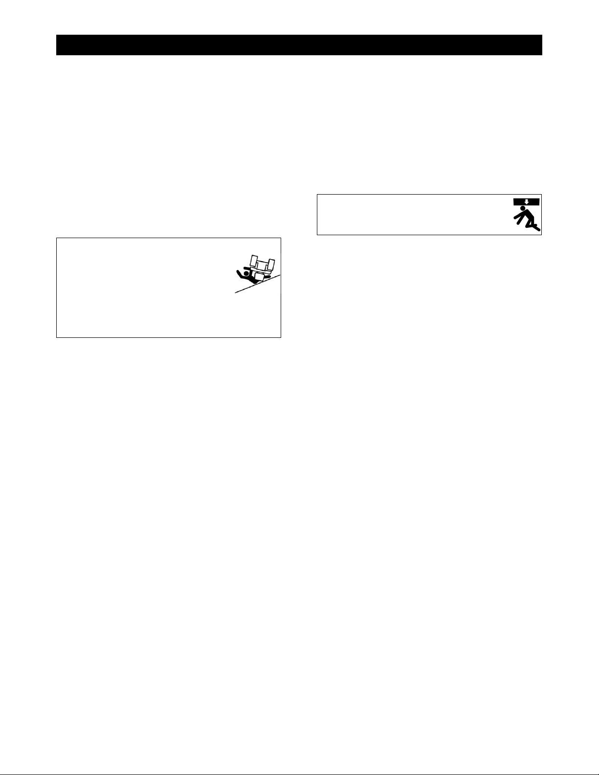
• Use extreme caution when guiding the
equipment up and down
ramps. Slowly drive the
equipment forward down the
ramp. Slowly back the
equipment in reverse up the ramp.
Avoid standing directly downhill from the
equipment to prevent machine rollover.
• Place the equipment in STOP and turn off
the engine once the equipment is loaded in
the truck/trailer.
• Chock the wheels and secure the saw in the
truck/trailer prior to transporting.
• Refer to the Department of Transportation
(DOT) for additional transportation
recommendations.
Lifting Safety
• Move yourself and all others away
from the lifting area when hoisting
the saw to prevent being crushed.
• Secure the appropriate hoisting cables, straps,
and/or chains to the saw’s designated lift points
prior to hoisting.
• Never use the tie-down brackets (applicable
models) to lift the saw.
• DO NOT attempt to lift the saw irresponsibly
and/or improperly.
14

OPERATING
Operating
General Operating Precautions
• Prior to operating the machine, read the
operator’s manual thoroughly and ensure
that you understand the safe and proper
operation of the machine.
• Use approved personal protective
equipment at all times while operating the
machine.
• Ensure that there is firefighting equipment
and a first aid kit nearby while operating the
machine.
• Ensure the cutting area is free of
obstructions, people, and or animals prior
to operating the machine.
• Always operate the machine from the
operator’s position at the rear of the
machine between the handlebars.
• Do not stand in front or behind the blade
path while the engine is running.
Handlebars
The handlebars help to guide and maneuver
the saw.
Adjusting the Handlebars
1. Loosen both of the handlebar lock knobs.
2. Hold the handlebar grip and place the first
handlebar into the handlebar opening
below the handle lock knob. The handlebar
can fit through two different angled
pathways inside the handlebar opening.
Select the handlebar angle that works best
for the current task.
3. Move the handlebar forward or backward to
adjust the length.
NOTE: Maintain a minimum of 6” of handlebar
into the handlebar tube at all times.
4. Tighten the handlebar lock knob to secure
the handlebar.
Handlebar and Lock Knob
5. Repeat steps 2 – 4 to secure the second
handlebar. Adjust the handlebar orientation
and length prior to operating the saw.
Control Grip Pushbuttons
The control grip pushbuttons raise and lower
the saw and blade (buttons work with engine
off).
Control Grip Pushbuttons
1. Press the Raise (left) pushbutton to raise
the saw and blade, and release to stop.
Note: Always raise the blade when
maneuvering the saw to provide proper
clearance between the blade and the ground.
2. Press the Lower (right) pushbutton to lower
the saw and blade, and release to stop.
15

OPERATING
Blade Lowering Speed (Optional)
Turn the Blade Lowering Speed valve
counterclockwise to increase the blade’s
lowering speed and clockwise to decrease the
blade’s lowering speed.
Note: The valve does not adjust the blade’s
raising speed.
Blade Lowering Speed Valve
Spotlight (Optional)
1. Loosen both spotlight bar lock knobs and
slide the bar from side to side to adjust the
length of the bar.
Spotlight and lock knobs
2. Tighten the lock knobs to secure.
3. Turn the spotlight switch ON or OFF as
needed for additional lighting.
Fuel System
WARNING
• Always use caution when refueling.
• DO NOT operate the saw with a fuel
leak.
• DO NOT fuel the saw with
the engine running.
• DO NOT smoke or expose
fuel to open flames when filling the fuel
tank or working with fuel.
CAUTION
• Clean up any spilled fuel prior to
starting the engine.
• Fuel may seep out from the fuel cap
vent (applicable models) when raising
the saw if the fuel tank is overfilled.
Adding Fuel
1. Lower the saw to level the frame.
2. Turn the ignition switch to OFF and let the
engine cool down.
3. Remove the fuel tank cap.
4. Fill the fuel tank using unleaded gasoline
with a minimum of 87 octane. DO NOT
overfill the tank for expansion purposes.
Refer to the engine manual for additional
information on appropriate fuels in normal
and cold weather temperatures.
5. Replace the fuel tank cap and secure.
Blade Guard
WARNING
DO NOT operate the saw with the blade guard
raised or removed.
DO NOT remove the blade guard with the
engine running.
Blade exposure should not exceed 180° while
cutting.
Always pivot the front of the blade
guard 180° (fully upward) so the
guard does not swing down
unexpectedly, which may cause serious
injuries.
Always secure the pivoted section of the blade
guard using the detent pin (guards 26” and
up).
When pivoting the front of the blade guard,
raise/lower it cautiously and slowly to avoid
serious injuries.
The blade guard shields the blade and must
always be in place when operating the saw.
Blade guards generally stay in place at all
times, except for when changing to another
guard size or when using the guard on the
opposite side of the saw. Regularly inspect the
blade guard and water tubes. Clean, repair, or
replace dirty or damaged components
immediately.
Note: Always use a guard size that matches
the blade size. Refer to the CC3500J Parts List
for additional information.
16

OPERATING
Installing the Blade Guard
Always install the blade guard with the blade
off the saw.
1. Holding the blade guard handle, face the
front of the blade guard forward and fit the
tapered mount on the side of the guard
onto the tapered mount on either the frame
base (right side of saw) or the belt guard
(left side of saw).
Frame Base Mount
2. Insert the lock pin through the hole on the
tapered mount to secure the guard.
3. Connect the water supply hose to the blade
guard.
Removing the Blade Guard
Always remove the blade guard with the blade
off the saw.
1. Disconnect the water supply hose from the
blade guard.
2. Remove the lock pin from the tapered
mount.
3. Use the handle on the blade guard to rock
the guard back and forth while lifting the
guard off the tapered frame base or belt
guard mount.
Flange Guard
Install the flange guard over the flange
assembly not in use for protection against dust,
debris, and slurry.
Note: Secure the blade shaft bolt not in use to
the front of the flange guard.
Installing the Flange Guard
1. Fit the tapered mount on the back of the
flange guard onto the tapered mount on
either the frame base (right side of saw) or
the belt guard (left side of saw).
2. Insert the lock pin through the hole on the
tapered mount to secure the guard.
Removing the Flange Guard
1. Remove the lock pin from the tapered
mount.
2. Remove the flange guard from the tapered
mount.
Diamond Blades
WARNING
• DO NOT exceed the blade’s
maximum recommended
speed when cutting.
Excessive blade speeds can cause
blade breakage, resulting in serious
injuries and/or death.
• DO NOT use damaged blades when
cutting to avoid harming yourself,
others, or the saw.
Using the proper blade (size and type)
preserves the blade and improves efficiency,
resulting in lower costs. Refer to the
Association of Equipment Manufacturers
(AEM) safety brochure for diamond blades and
www.diamondproducts.com for additional
blade information.
Inspecting the Blade
Inspect each blade prior to installation and
discard all damaged blades. Inspect the blades
for:
• Cracks, nicks, and dents
• A damaged/deformed arbor (center hole)
• Darkness/discoloration near edge of blade
• A deformed blade circumference
• Segment loss/cracks
• Core wear
• Bending
• Uneven side-widths
17

OPERATING
Blade Speed
Refer to the CC3538JK RPM Chart, the blade,
or the blade packaging information for the
recommended blade speeds when cutting. DO
NOT exceed the maximum recommended
blade speed. DO NOT use a blade for cutting
that requires a lower speed than the minimum
blade shaft speed.
Wrench
Use the wrench provided when installing or
removing a blade. Apply force to the opposite
end of the wrench and tighten the blade shaft
bolt/screw to 125 ft-lb (169.5 Nm) to secure the
outer flange and blade. Verify this
measurement with a torque wrench.
Wrench
Installing the Blade
WARNING
• DO NOT install a blade with
the engine running.
• Failure to properly secure the
outer flange and blade may cause parts
to loosen or fall off the saw, resulting in
serious injuries or death!
• DO NOT pivot the front of the blade
guard up or down when installing very
large blades. Attempting to pivot the
front of a heavy guard when the guard
is positioned higher up for blade
installation makes the guard difficult to
lift and/or lower. In this situation,
remove the blade guard front instead of
pivoting it.
• Always secure the pivoted section of
the blade guard using the detent pin
(guards 26” and up).
CAUTION
• Wear gloves and be alert to the
surrounding environment when
handling blades.
The blade can be installed on the right or left
side of the saw. Install the blade on the side
preferred or most appropriate for the cutting
task.
1.
Select a blade size and type. Remember to
check the blade for damages and discard
as necessary.
Note: If changing the blade size, adjust and/or
change all necessary saw components
according to the information in the CC3500J
Parts List.
2.
Remove the detent pin (guards 26” and up)
from the guard hinge and pivot the front of
the blade guard 180° (fully upward) to gain
access to the blade flanges.
Detent Pin and Hinge Screw
3.
On pivoted guards, insert the detent pin
through the interlocking barrels on the top
of the guard to secure the front of the
guard.
Note: Failure to fully pivot and secure the front
of the guard may cause serious injuries.
4. Remove the blade shaft screw (clockwise
loosens on right side, counterclockwise
loosens on left side) using the wrench.
5. Carefully remove the outer flange. Inspect
the flange assembly and clean or replace
dirty/damaged components.
6. Place the blade against the inner flange.
For large blades, carefully roll the blade up
to the inner flange. Adjust the height of the
saw to align the flange and blade arbor.
Note: Point the arrow printed on the blade in
the direction of the blade shaft’s rotation.
7.
Align and fit the outer flange and flange pin
through the blade and into the inner flange
and blade shaft.
18

OPERATING
Note: The outer flange should fit snug with the
blade, inner flange, and blade shaft.
8. Slightly rotate the outer flange and blade
backward to eliminate backlash
(looseness) between parts.
9. Place the wedge lock washer onto the
blade shaft screw and insert the screw into
the blade shaft through the center of the
outer flange.
10. Tighten the screw by hand (use left-hand
threaded screw on right side of saw only).
Slowly lower the saw, if necessary, until the
blade just touches the ground.
11. Tighten the screw again, using the wrench,
to 125 ft-lb (169.5 Nm) to secure the outer
flange and blade. Verify this measurement
with a torque wrench.
12. Remove the detent pin (guards 26” and up)
from the guard hinge and pivot the front of
the guard down over the blade to secure.
Reinsert the pin through the double barrel.
Removing the Blade
CAUTION
• DO NOT remove a blade with
the engine running.
• DO NOT pivot the front of the blade
guard up or down when removing very
large blades. Attempting to pivot the
front of a heavy guard when the guard
is positioned higher up for blade
removal makes the guard difficult to lift
and/or lower. In this situation, remove
the blade guard front instead of pivoting
it.
• Always secure the pivoted section of
the blade guard using the detent pin
(guards 26” and up).
1. Remove the detent pin (guards 26” and up)
from the guard hinge and pivot the front of
the blade guard 180° (fully upward) to gain
access to the blade.
2. On pivoted guards, insert the detent pin
through the interlocking barrels on the top
of the guard to secure the front of the
guard.
Note: Failure to fully pivot and secure the front
of the guard may cause serious injuries.
3. Slowly lower the saw, if necessary, until the
blade just touches the ground.
3. Remove the blade shaft screw using the
provided wrench.
4. Carefully remove the outer flange and
blade. Place the blade in an appropriate
storage location.
Note: If the outer flange is difficult to remove,
tighten a setscrew into two of the holes on the
outside of the outer flange to help separate the
outer flange from the blade. Remove the
setscrews when separated.
5. Inspect the flange assembly and clean or
replace dirty/damaged components.
6. Carefully fit the outer flange back into the
inner flange and/or blade shaft.
7. Place the wedge lock washer onto the
blade shaft screw and insert the screw into
the blade shaft through the center of the
outer flange.
8. Retighten the blade shaft screw to secure
the flanges.
9. Remove the detent pin (guards 26” and up)
from the guard hinge and pivot the front of
the guard down over the blade flanges to
secure. Reinsert the pin through the double
barrel.
Engine
WARNING
• Operate the saw in well-
ventilated areas. Concentrated engine
exhaust can cause loss of
consciousness and/or death.
• DO NOT touch the engine/muffler with
the engine running, and always let them
cool down prior to touching or servicing
the saw.
• DO NOT leave the saw unattended
while the engine is running.
19

OPERATING
Vernier Throttle
V
ernier Throttle
1. Turn the Hold/Release knob
counterclockwise to loosen the knob.
2. Turn the throttle counterclockwise to
increase the engine speed or push in the
throttle’s spring-loaded tip and pull the
throttle out to increase the engine speed.
Turn the throttle clockwise to decrease the
engine speed or push in the throttle’s
spring-loaded tip and push the throttle in to
decrease the engine speed.
Note: The engine must run at half throttle or
greater when maneuvering the saw with
power.
3. Turn the Hold/Release knob clockwise to
tighten the knob and secure the engine
speed.
Tasks Prior to Starting the Engine
Complete the tasks listed below prior to
starting the engine to ensure a safe start:
• Check fluids and fill to appropriate levels.
• Place speed control lever at STOP.
• Disengage transmission.
• Turn off controls and switches.
• Remove tools from area.
NOTE: The engine will not start with the
emergency stop button pushed down. Always
pull out the emergency stop button prior to
operating the saw.
Starting the Engine
Note: In an emergency, press the emergency
stop button to immediately stop the engine and
any saw movement!
1. Open the fuel shutoff valve.
2. Insert the key into the ignition, turn it to
START, and release when the engine
starts. Refer to the information in the
engine manual when starting the engine in
cold weather.
Note: If the engine does not start within 10
seconds, turn off the key and try again
approximately 30 seconds later. Refer to the
engine manual for troubleshooting
recommendations after several failed attempts.
3. Let the engine warm up for several
minutes. Check all warning lights and turn
off the engine immediately to fix any
problems prior to operating the saw.
4. Adjust the engine speed as necessary for
maximum efficiency while operating. Refer
to the engine manual for additional
information.
Stopping the Engine
CAUTION
• DO NOT leave the saw unattended until
the engine is off and the blade has
stopped spinning.
1. Place the speed control lever at NEUTRAL
and raise the blade from the cut.
2. Turn off all controls, switches, and water.
3. Decrease the engine speed to idle for five
minutes to cool down the engine.
4. Turn the ignition key to OFF and remove
the key.
Transmission Lever
Disengage the transmission prior to starting
the engine to prevent unnecessary saw
movement.
Note: The engine must run at half throttle or
greater for proper transmission efficiency when
maneuvering the saw with power.
20
This manual suits for next models
4
Table of contents
Other Diamond Products Cutter manuals


