Diamond Products CB215 User manual

CORE BORE
PARTS LIST
MODEL
CB215
JULY, 2023
& OPERATOR'S MANUAL


Table of Contents
Description Page No.
1. Included Parts …………………………………………………………….......4
2. General Safety Rules ………………………………………………………...5-8
3. Operating Instructions ………………………………………………………..9-14
4. Wiring Diagram ……………………………………………………………….15
5. CB215 Exploded View ……………………………………………………….16
6. CB215 Parts …………………………………………………………………..17-18
Model D-Handle Model
Power Input 230-240 V: 2200 W, 220 V: 2000 W, 110-120 V: 1700 W
Voltage See machine nameplate
No Load min-1 1000 / 1600 / 4450
Rated Load min-1 650 / 1040 / 2890
Capacity-Wet (Rig-Mounted) 162 mm (6 1/4")
Capacity-Dry 202 mm (8")
Arbor Thread 1 1/4"UNC & 1/2" BSP
Neck Diameter 60 mm
Dimensions 528 mm x 106 mm x 145 mm
Gear Oil Type 80W-90
Gear Oil Capacity 200 ml
Net Weight 5.8 kg (12.8 lb)
3. 4.
1. 6.
8.
7.
9.
11.
2.
10.
11.
12. 13.
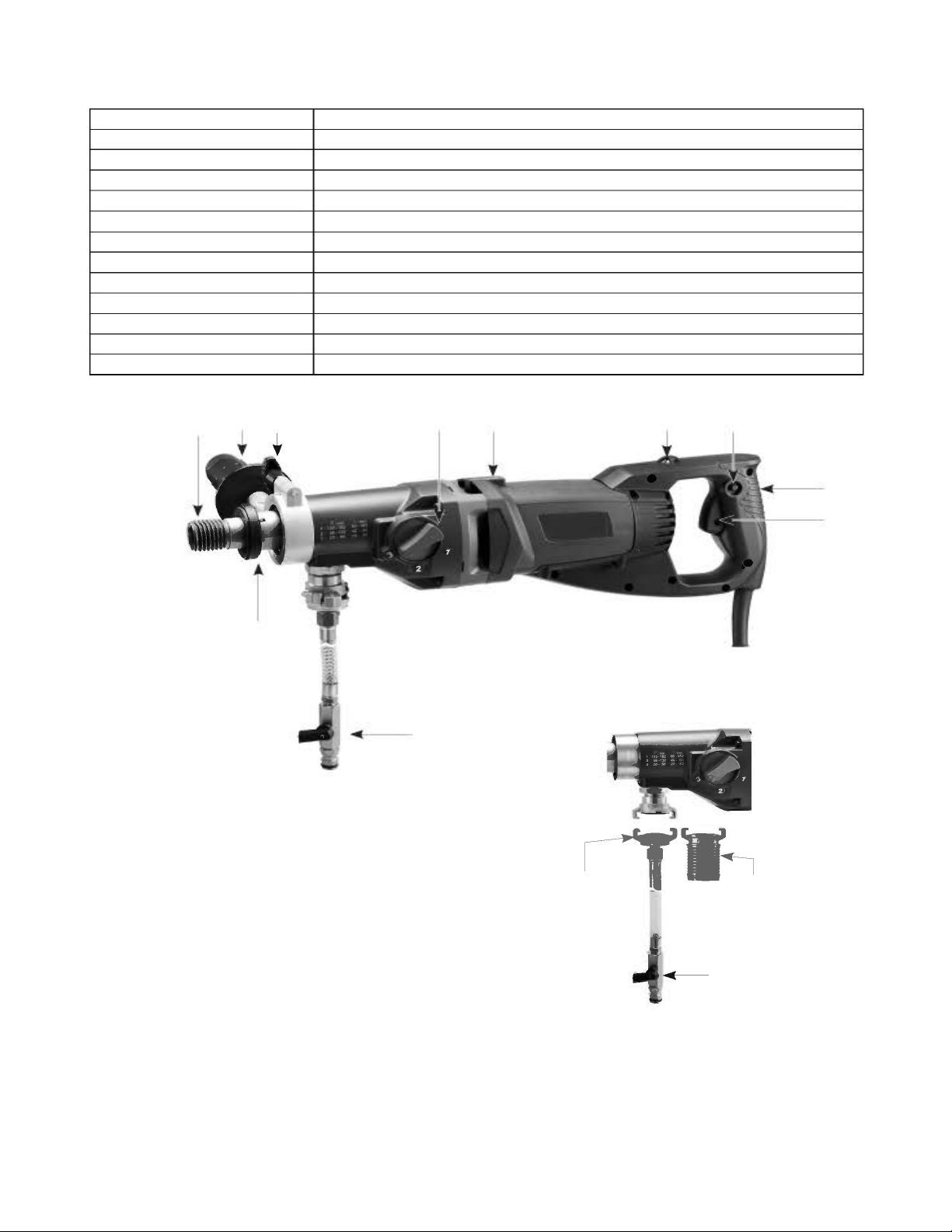
1. Spindle 1-1/4"UNC & 1/2"BSP
2. Side Handle Assy.
3. Side Handle Lock Screw
4. Gear Selector
5. Tubular Spirit Level
6. Indicator Light
7. Lock Button
8. Main Handle
9. Trigger Switch
10. Anti-Seize Ring
11. Water Feed Valve
12. Water Feed Adaptor Head
13. Vacuum Adaptor Head
~
I J
l
l
l
'
' I
'
-
~
~
l
J
l
l
l
l
1
5.
4

General Safety Rules
WARNING! Read all safety warnings and all instructions. Failure to follow the
warnings and instructions may result in electric shock, fire,and/or serious injury.
Save all warnings and instructions for future reference.
The term “power tool” in the warnings refers to your main-operated (corded) power tool or battery-operated (cordless) power tool.
1. WORK AREA SAFETY
a. Keep work area clean and well lit. Cluttered and dark areas invite accidents.
b. Do not operate power tools in explosive atmospheres, such as in the presence of flammable liquids, gases or dust.
Power tools create sparks which may ignite the dust or fumes.
c. Keep children and bystanders away while operating a power tool. Distractions can cause you to lose control.
d. Never leave the electric power tool unattended. Only leave the machine when the tool in use has come to a complete standstill.
2. ELECTRICAL SAFETY
a. Power tool plugs must match the outlet. Never modify the plug in any way. Do not use any adapter plugs with earthed
(grounded) power tools. Unmodified plugs and matching outlets will reduce risk of electric shock.
b. Avoid body contact with earthed orgrounded surfaces, such aspipes, radiators, ranges and refrigerators. There is an
increased risk of electric shock if your body is earthed or grounded.
c. Do not expose power tools to rain or wet conditions. Water entering a power tool will increase the risk of electric shock.
d. Do not abuse the cord. Never use the cord for carrying, pulling or unplugging the power tool. Keep cord away from heat,
oil, sharp edges or moving parts. Damaged or entangled cords increase the risk of electric shock.
e. When operating a power tool outdoors, use anextension cord suitable for outdoor use. Use ofa cord suitable for outdoor
use reduces the risk of electric shock.
f. If operating a power tool ina damp location isunavoidable, use a residual current device (RCD) protected supply. Use of
an RCD reduces the risk of electric shock.
3. PERSONAL SAFETY
a. Stay alert, watch what you are doing and use common sense when operating a power tool. Do not use a power tool
while you are tired or under the influence of drugs, alcohol or medication. A moment of inattention while operating power
tools may result in serious personal injury.
5
w

6
b. Use personal protective equipment. Always wear eye protection. Protective equipment such as dust mask, non-skid safety
shoes, hard hat, or hearing protection used for appropriate conditions will reduce personal injuries.
c. Prevent unintentional starting. Ensure the switch is in the off-position before connecting to power source and/or battery
pack, picking up or carrying the tool. Carrying power tools with your finger on the switch or energizing power tools that have
the switch on invites accidents.
d. Remove any adjusting key orwrench before turning the power tool on. Awrench ora key left attached to a rotating
part of the power tool may result in personal injury.
e. Do not overreach. Keep proper footing and balance at all times. This enables better control of the power tool in
unexpected situations.
f. Dress properly. Do not wear loose clothing or jewelery. Keep your hair and clothing away from moving parts. Loose
clothes, jewelery or long hair can be caught in moving parts.
g. If devices are provided for the connection of dust extraction and collection facilities, ensure these are connected and
properly used. Use of dust collection can reduce dust related hazards.
h. Do not let familiarity gained from frequent use oftools allow you tobecome complacent and ignore, tool safety
principles. A careless action can cause severe injury within a fraction of a second.
4. POWER TOOL USE AND CARE
a. Do not force the power tool. Use the correct power tool for your application. The correct power tool will do the job better
and safer at the rate for which it was designed.
b. Do not use the power tool if the switch does not turn it on and off. Any power tool that cannot be controlled with the
switch is dangerous and must be repaired.
c. Disconnect the plug from the power source and/or battery pack from the power tool before making any adjustments,
changing accessories, or storing power tools. Such preventive safety measures reduce the risk of starting the power tool
accidentally.
d. Store idle power tools out of the reach of children and do not allow persons unfamiliar with the power tool or these
instructions to operate the power tool. Power tools are dangerous in the hands of untrained users.
e. Maintain power tools. Check for misalignment or binding of moving parts, breakage of parts and any other condition
that may affect the power tool‘s operation. If damaged, have the power tool repaired before use. Many accidents are
caused by poorly maintained power tools.
f. Keep cutting tools sharp and clean. Properly maintained cutting tools with sharp cutting edges are less likely to bind and are
easier to control.
g. Use the power tool, accessories and tool bits etc. in accordance with these instructions taking into account the working
conditions and the work to be performed. Use of the power tool for operations different from those intended could result in a
hazardous situation.
h. Keep handles dry, clean and free of oil and grease. Slippery handles do not allow for safe handling and control of the tool in
unexpected situations.

7
5. SERVICE
a. Have your power tool serviced by a qualified repair person using only identical replacement parts. This will ensure that the
safety of the power tool is maintained.
b. Only use original parts for repair and maintenance. The use of incompatible accessories or spare parts can result in electric
shocks or other injuries.
Symbols used in this manual
V…….......volts
A…….......amperes
Hz……......hertz
W……......watt
~………....alternating current
n
0
………..no load speed
min-1…......revolutions or reciprocation
per minute
......warning of general danger
......class II tool
.......read these instructions
......always wear eye protection
......always wear a dust mask.
.....always wear hearing protection
.....wear safety-approved hard hat
do not dispose of electric tools,
accessories and packaging together with
household waste material
DRILL SAFETY WARNINGS
• Use auxiliary handle(s). Loss of control can cause personal injury.
• Hold power tool by insulated gripping surfaces, when performing an operation where the cutting accessory may contact
hidden wiring or its own cord. Cutting accessory contacting a "live" wire may make exposed metal parts of the power tool "live"
and could give the operator an electric shock.
• Never use the machine without the PRCD fault-current safety switch supplied.
• Always check the PRCD fault-current safety switch for correct functioning before starting a drilling operation.
• Ensure that no water is allowed to get into the motor unit during operation.
• If you detect a leak in any part of the water supply system, shut the machine down immediately and repair the fault.
Water pressure should not exceed 70 psi (4 bar).
• Block off the working area and place warning signs on both sides of the wall when drilling through from one side to the
other.
• Take appropriate precautions to ensure that, in the event of a drilling core dropping out, no personal injury or material
damage will result.
• When drilling hollow components, check the flow route of the cooling water in order to prevent damage.

8
INTRODUCTION
The machine is equipped with spirit levels which aid in aligning the tool. This machine is for the intended purpose of diamond core
drilling of concrete, masonry, stone and similar materials. The machine may be hand-held for drilling up to 80mm. For sizes above
80mm, it must be mounted on a rig (drilling stand). The rig is not included. All other uses which are not for the intended purpose are
prohibited.
It is equipped with two adaptor heads: one for water feed and one for through-the-spindle dust aspiration. It is equipped with a PRCD
interrupter (portable residual current device) which must be used at all times. It is equipped with a three speed mechanical gearbox for
different core drill size ranges and features a mechanical safety clutch.
The motor has electronics for soft start, overload protection and thermal (overheating) protection. There is an indicator light on the
machine to alert the operator of load and temperature conditions.
ELECTRICAL CONNECTION
The network voltage must conform to the voltage indicated on the tool name plate.
Under no circumstances should the tool be used when the power supply cable is damaged. Adamaged cable must be
replaced immediately by an authorized Customer Service Center. Do not try to repair the damaged cable yourself. The use of
damaged power cables can lead to an electric shock.
WARNING:
This machine is equipped with a Portable Residual Current Device (PRCD) also known as a Ground Fault Circuit Interrupter
(GFCI). Always use this device whenever using the machine to reduce the risk of shock hazards. Test and reset the PRCD
device before each use. Press the “Test” button to test. Press the “Reset” button to energize the circuit.
WARNING!: 110V UK machines are not equipped with a PRCD portable residual
current device or GFCI ground fault circuit interrupter. The machine must
always be used with an isolating transformer for protection in case an
electrical fault should occur.
Use an RCD in a separate control box with one or more socket outlets in
accordance with EN 60309-2 with the earthing contact position 1 h.
ASSEMBLY
1. Mount the handle clamp of the side handle onto the gearbox neck. Position the side handle perpendicular to the main handle. Use
the lock screw to tighten the clamp.
2. Insert either the water feed adapter head or the vacuum adapter head into the port.
Test Button
Reset Button
On Lamp

9
LIST OF CONTENTS
• Diamond core drilling machine.
• Side handle assembly
• Water Feed Adaptor Head
• Vacuum Adaptor Head
• Wrench
OPERATING INSTRUCTIONS
1) MOUNTING THE CORE BIT
CAUTION: Ensure that the threads of the spindle and the core bit match. Attempting to mount mismatched threads will result in
damage to both threads.
The spindle has two types of threads. The outside male thread is 1-1/4inch UNC, the inside female thread is 1/2 inch BSP.
Ensure both the core bit and the machine spindle are clean. Any debris could cause excessive run-out of the mounted core bit. Excessive
run-out can cause premature failure of the core bit and/or a safety hazard. Tighten the bit to the spindle using two wrenches.
Choosing the correct core bit for the job
Ensure that the bit you are using is suitable for the material you are drilling. There are two main types of diamond core bit:
-Wet bits (Always use water with wet bits)
-Dry bits
2) WATER SUPPLY
Water is a basic requirement for diamond core drilling. The water serves as a coolant to avoid the
working surface at the tip of the bit from overheating. To connect the water supply. Attach the
quick-release water coupling to a water hose.
WARNING: Check all connections of the water feed system to ensure there are no leaks.
Inspect hoses and other critical parts which could deteriorate.
WARNING: The maximum water pressure should not exceed
70 psi (4 bar).
Indicator Holes
Open
Closed
Water Feed Valve

10
CAUTION: There are two small holes on the top of the gear case. If either of these holes leaks water, it indicates that the water
seals are worn out. Replace them immediately.
Use a water collector with a wet vacuum to collect cooling water if nearby objects could be damaged by water.
WARNING: Never allow water to enter the motor. A perfectly functioning water collector set up must be used for any drilling
performed at an upward angle.
Instructions for Inserting Adapters for Convertible models:
Insert fully and then twist clockwise to tighten.
3) SELECTING SPEEDS
CAUTION: Never attempt to change gears on a running machine! Only adjust when the machine is at rest.
Select the desired gear range by turning the gear selector either clockwise or
counterclockwise into the desired gear. It will usually be necessary to turn the spindle
by hand a little to get it to shift all the way.
WET DRILLING RECOMMENDED GEARS (reinforced concrete)
DRY DRILLING RECOMMENDED GEARS (soft materials)
Gear
BitØ
20mm 32mm 56mm 132mm 162mm 202mm
Gear 3
Gear 2
Gear 1
Impossible /
Not recommended Possible Ideal
Gear
BitØ
14mm 24mm 35mm 92mm 132mm 162mm
Gear 3
Gear 2
Gear 1
Gear Selector
• Q

11
4) THE SWITCH
The machine has a lockable trigger switch. Squeeze the trigger to start the machine. To
lock the switch on, press the lock button while holding the trigger switch on. To release,
squeeze the trigger and release.
WARNING: Never lock the switch on when drilling hand-held. Only lock the switch on when mounted to a rig.
5) OVERLOAD PROTECTION, OVERHEAT PROTECTION
Overload Warning System:
When the load reaches overload conditions, the indicator light will flash on and off.
Overload:
If the excessive load is sustained too long, the motor will shut down completely and the LED indicator light will glow solid red. In this
case, the motor must be first shut off and then restarted.
Overheat Thermal Protection:
If the temperature of the motor gets too high, the thermal protection will shut the motor down and the LED indicator light will glow
solid red. The switch must be first shut off and then restarted.
CAUTION: The motor will be damaged if it is repeatedly overloaded or overheated. Always cool the motor by running at no
load for a few minutes whenever it stops from either overheat or overload.
6) SAFETY CLUTCH
This machine is equipped with a mechanical clutch to protect the operator and machine from excessive torque forces. After the clutch
slips many times, it will become worn and slip at lower and lower torque levels. When this happens, it must be serviced by an authorized
service provider. The recommended torque of the clutch nut is 21 Nm.
7) DIAMOND CORE DRILLING
1. Press the “Reset” button on the PRCD interrupter device to energize the circuit to the machine.
Then squeeze the trigger switch to turn the machine on.
2. Open the water valve slightly and very gently begin the cut. If holding by hand, start the cut by approaching at an angle of about
30 degrees to the cutting surface. (A large piece of wood with a large V notch cut in it will help prevent the bit from wandering at
the beginning.) Once about a third of the arc is cut, straighten the bit to the correct perpendicular angle while keeping enough
feed pressure on the bit to prevent it from wandering.
3. Make adjustments to the water feed as needed. The water leaving the cut should be a solid colored slurry with about the
consistency of milk.
4. Once in the cut, use steady feed pressure .
5. When breaking through, hold the machine tightly and reduce feed pressure .
Trigger Switch
Lock Button
Indicator Light

WARNING: Always keep your face away from the machine.
The diamond impregnated segments in a wet type (sintered) diamond core bit operate on a principle of controlled erosion. The bond
matrix holding the diamonds is continually worn away by abrasion with the work piece, exposing the harder diamonds to stand proud
from the bond matrix.
Without adequate water, the bit would overheat and be destroyed.
With too much water and not enough feed pressure, there would not be adequate erosion of the bond matrix and the bit becomes dull.
This is called glazing. If the bit seems to refuse to cut anymore, it is glazed. See below: ”SHARPENING A GLAZED BIT ”
Don’t feed too gently or the diamond segments will become glazed. Keep the bit steadily working.
If holding by hand, take great care to keep the bit aligned to the hole. If the bit is crooked, it will easily bind.
If the cut is very deep, the core plug may be obstructing the flow of cooling water. In this case, stop drilling, and chisel out the core plug
before continuing.
CAUTION: If the bit gets stuck, do not try to rock it loose by turning the switch on and off. That is hazardous and could damage
the motor. Rather, unplug the machine and use a wrench on the bit mounting to work it loose.
If embedded steel such as rebar is encountered, take special care. Reduce the feed pressure by about 1/3 and let the bit go at its own
pace.If there is too much vibration,the bit will be destroyed.
Once the steel is passed, continue normally.
CAUTION: Drilling operations are very stressful to the motor and at the end of the cut, the motor temperature will be very hot,
always run the motor at no load for a few minutes until the temperature returns to a normal range before shutting off.
RESHARPENING A GLAZED BIT
If the bit becomes glazed, resharpen by dressing with an appropriate alumina oxide or silicon carbide dressing stone. Simply drill into the
stone as many times as necessary to restore its cutting performance.
VIBRATION TROUBLESHOOTING
If vibration occurs and it is not caused by embedded steel, stop drilling to find the cause and remedy.
CAUTION: Do not operate with vibration or there will be serious hazard and the diamond core bit will surely be destroyed.
12

13
Vibration is usually caused by:
1. A bit with too much runout
SOLUTION: Replace bit.
2. A bit with diamond segments broken off
SOLUTION: Repair or Replace bit.
MAINTENANCE
Every 50 hours of operation blow compressed air through the motor while running at no load to clean out accumulated dust.
Always check for a damaged power supply cable, check for loose fasteners and always keep alert for unusual noises and vibration
when operating.
WARNING: Never operate a damaged machine. Always tag a damaged machine and take it out of service until repairs can
be made.
CAUTION: This machine is equipped with an oil bath gearbox. To avoid leakage of lubricating oil, whenever the gearbox is
opened, the o-ring seal must be replaced with a new one.
Maintenance which should be performed by an authorized service center, include the following:
• Replace water seals as needed.
• Replace the carbon brushes as needed
• Change the gear oil about every 100 hours of operation
• Replace the clutch discs and spring as needed.
THE CARBON BRUSHES
The carbon brushes are a normal wearing part and must be replaced when they reach their wear limit. This machine is equipped with
auto-stop carbon brushes. If the machine comes to a stop unexpectedly, the brushes should be checked. The auto-stop brush design
protects the motor by stopping the machine before the carbon brushes are completely worn out.
Caution: Always replace the brushes as a pair.
To replace:
1. Remove the 14 screws to remove the D-handle and tail cover. Carefully move the parts to one side, taking care not to strain the
wiring.
2. Using pliers rotate the brush spring out of the way and slide the old carbon brush out of the brush holder.
3. Unscrew the screw to remove the brush lead. The old carbon brush may now be lifted away.
4. Install a new brush. Installation is the reverse of removal.
5. Replacement of the D-handle is the reverse of removal. Take care not to pinch any wires when reassembling.

14
If the replacement of the power supply cord is necessary, this has to be done by the manufacturer or their agent in order to
avoid a safety hazard.
WARNING: All repairs must be entrusted to an authorized service center. Incorrectly performed repairs could lead to injury or death.
Do not throw electric power tools into the household waste!
In accordance with the European Directive 2012/19/EU on Waste Electrical and Electronic Equipment and transposition into national law,
used electric power tools must be collected separately and recycled in an environmentally friendly manner.
15
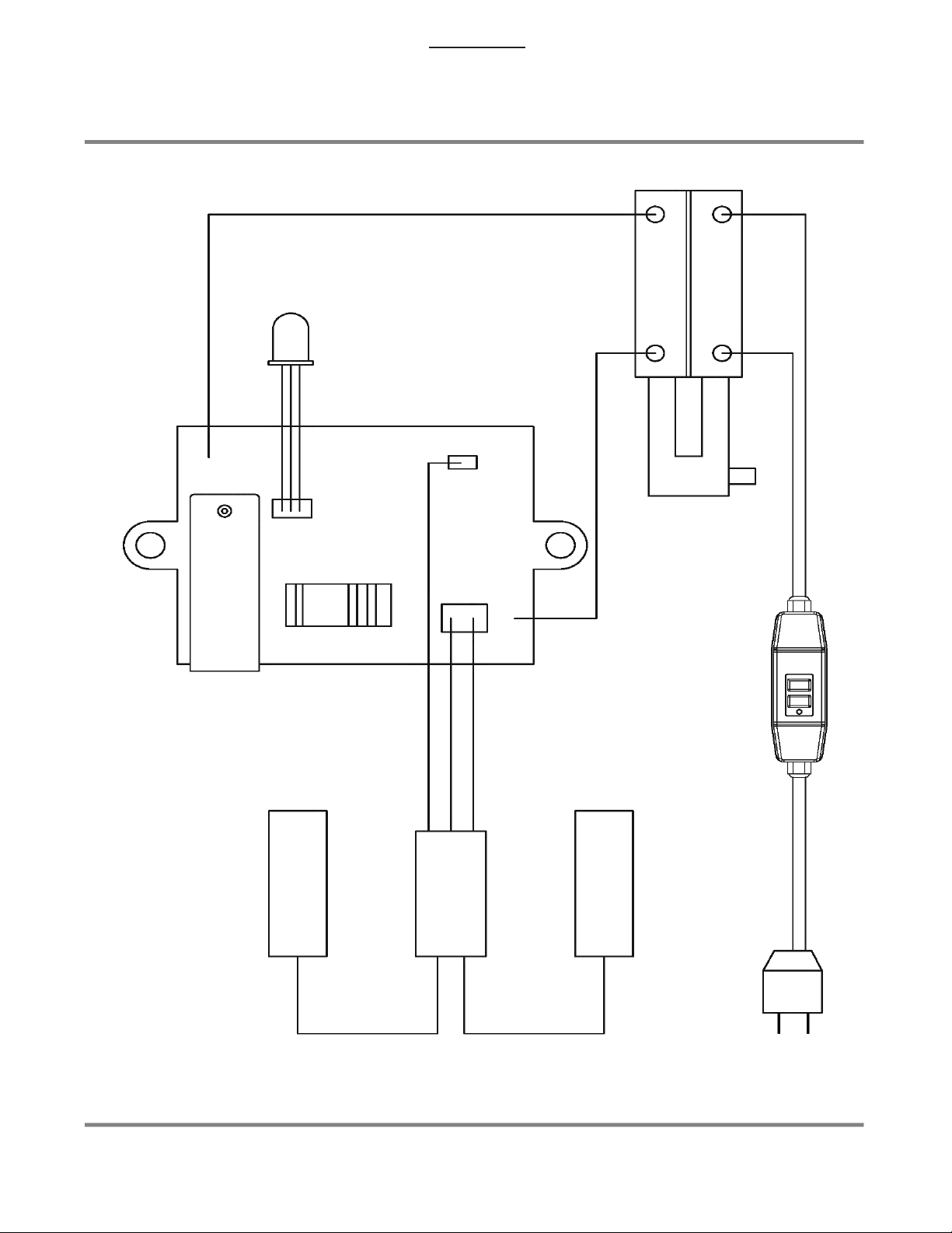
WIRING
1
2
1
2
AC
BRUSH
BRUSH
STATOR
BLACK
BLACK
BLACK
BLACK
(TEMP. SENSOR)
ELECTRONICS
UNIT
SWITCH
WHITE
WHITE
BLUE
BROWN
BLACK
LED
BLUE
BROWN
PRCD
111
11111

80 81
82
83
01

ITEM PART NO. QTY. DESCRIPTION
12709988 1POWER SUPPLY CABLE (UL-14Ax2Cx1.4M-SJTW)
22709989 1PRCD INTERRUPTER PROTECTION (110V)
32709990 1POWER SUPPLY CABLE (NO PLUG-14Ax2Cx1.6M-SJTW)
46078403 1CORD ARMOR
56071331 1SWITCH ACTUATOR (BLACK)(LOCK-ON)
62709991 1ELECTRONICS UNIT (110V)
72709992 1D-HANDLE HALF-RIGHT (BLACK)
82709993 1D-HANDLE HALF-LEFT (BLACK)
92709004 7PANHEAD TAPPING SCREW-B (M4x25)
10 2709120 3PANHEAD TAPPING SCREW-B (M4x35)
11 2709121 4TORX PANHEAD TAPPING SCREW-C (M5x20)
12 2709994 1LED INDICATOR LIGHT
13 2709995 1CABLE CLIP
14 2709146 2PANHEAD TAPPING SCREW-B (M4x14)
15 2709996 4PANHEAD TAPPING SCREW-B (M4x10)
16 2709123 2BRUSH SPRING (0.4x4x3T)
17 6078412 2CARBON BRUSH HOLDER (7x17)
18 2709125 2INSULATION PLATE (10x38x1)
19 6078414 2CARBON BRUSH (7x17x19)(110V)
20 6078736 2PANHEAD MACHINE SCREW (M4-0.7 x 6)
21 2709128 1SPIRIT LEVEL (10x10x29)
22 2709997 1MOTOR HOUSING (GRAY-RAL7016)
23 2709998 1FAN SHROUD (BLACK)
24 2710137 1STATOR (110V-81x46.4x70)
25 2710138 2FEMALE SPADE TERMINAL(BLUE)
26 6078436 2SPRING WASHER (M5)
27 6078745 2PANHEAD TAPPING SCREW-A (M5x90)
28 2710139 1BALL BEARING (6200)
29 2710140 1ARMATURE (110V-81x45.8x70)
30 2710141 1BALL BEARING (6201)
31 2710142 1OIL SEAL (Ø12xØ22x7)
32 2710143 1GEAR PLATE (ORANGE-021C)
33 2710144 1O-RING (Ø92x2)
34 2709032 1NEEDLE BEARING (HK 1010)
35 2709086 1INTERNAL CIRCLIP (IS14)
36 2710145 1OUTPUT GEAR (M1.25x29T)
37 2710146 1SPINDLE GEAR (M1.25x42T)
38 2709033 1INTERNAL CIRCLIP (IS18)
39 2710147 1OUTPUT GEAR (M1.25x46T)
40 2710148 1OIL SEAL (Ø22xØ32x7)
41 2709140 2BALL BEARING (608)
42 2709141 1CLUTCH NUT (M10xP1.25x8.1T)
CB215 Parts

ITEM PART NO. QTY. DESCRIPTION
43 2709142 1PRESSURE DISC (Ø12.1xØ28x2.65)
44 2710149 1INPUT GEAR (M1.0x38T)
45 2710150 1BUSHING (Ø12xØ18x5)
46 2710151 1CLUTCH DISC SET
47 2710152 1INPUT SHAFT (M1.25x24Tx12Tx8T)
48 2710153 1SOCKET CAP SCREW (M5-0.8 x 12)
49 2709071 1SELECTOR DISC
50 2710154 1GEAR HOUSING (GRAY-RAL7016)
51 2709047 1O-RING (Ø20x3)
52 2710155 1GEAR SELECTOR (ORANGE-021C)
53 2710156 4PANHEAD TAPPING SCREW-B-W/WASHER (M5x60)
54 2710157 1OIL SEAL (Ø25xØ45x7)
55 2710158 1OIL SEAL (Ø25xØ47x7)
56 2710159 1EXTERNAL CIRCLIP (S-25)
57 2710160 1BALL BEARING (6205)
58 2710161 2STAINLESS BUSHING (Ø23xØ25x9)
59 2709090 1PARALLEL KEY (5x5x40)
60 2710162 1SPINDLE SET(1 1/4"-7 x 1/2"BSP)
61 2709161 1INTERNAL CIRCLIP (R-52)
62 2709056 2DOWEL PIN (Ø4x11.8)
63 2709057 1ANTI-SEIZE CUP
64 2709058 3O-RING (Ø32x1.5)
65 2709059 1THRUST RING (3252)
66 2709060 1ANTI-SEIZE RING
67 2709061 1O-RING (Ø45x1.5)
68 2709162 1HANDLE CLAMP (SILVER)
69 2710163 1HAND KNOB
70 2710164 1HEX BOLT (M6-1.0 x 60)
71 2709165 1FRONT HANDLE (M12xP1.75)
72 2710165 1NIPPLE
73 2710166 1SEAL (Ø19xØ26x3)
74 2710167 1GEKA FEMALE CLAW
75 2710168 2SEAL (Ø36xØ29.5x12)
76 2710169 1GEKA HOSE CLAW
77 2710170 1WATER FEED CONNECTOR KIT
78 2710171 1WRENCH (M32)
79 2710172 1WATER COUPLING (3/4')(BLACK)
802710173 1HALL EFFECT SWITCH
816071338 2PANHEAD TAPPING SCREW-B (M4x12)
826078731 1SPRING (Ø0.8 xØ6.4 x Ø8 x 9T x 26L)
832710174 2BUTT SPLICE CONNECTORS
842710175 1CARRY CASE (BLACK) (NOT SHOWN)
CB215 Parts

NOTES
____________________________________________________
____________________________________________________
____________________________________________________
____________________________________________________
____________________________________________________
____________________________________________________
____________________________________________________
____________________________________________________
____________________________________________________
____________________________________________________
____________________________________________________
____________________________________________________
____________________________________________________
____________________________________________________
____________________________________________________
____________________________________________________
____________________________________________________
____________________________________________________
____________________________________________________
____________________________________________________
____________________________________________________
____________________________________________________
____________________________________________________
____________________________________________________
____________________________________________________
____________________________________________________
____________________________________________________
____________________________________________________
____________________________________________________

Table of contents
Other Diamond Products Drill manuals


