Diamond Products CB700 User manual
OPERATIONS MANUAL
MODEL :
CORE DRILL
SAFETY
To maintain the operation safety,
make sure to read and understand
this instruction book BEFORE
operating this equipment.
CB700
DIAMOND
PRODUCTS

SAFETY
1. When operating the drill, be sure to wear proper safety gear, such as safety
glasses, dust mask, glove, and hearing protection. A hard hat is also
recommended.
2. Never operate unless proper footing and balance is possible at all time.
3. Wear proper apparel. Do not wear loose clothing or accessories. Keep hair
and body parts away from openings and moving parts.
4. Wet coring bits MUST be used with water. Flow should be kept at sufficient
rate and volume.
5. Use ONLY diamond impregnated core bits with this drill.
6. Do not force the machine. Use the drill properly and as intended.
7. Anchor bolts should always be used to secure the base on a cracked,
uneven or vertical surfaces.
8. Maintain alertness while operating the machine. Failure to maintain
attention, by the operator, may lead to serious injury.
9. Do no operate the machine when you are tired or while under the influence of
drugs, alcohol or any medication.
10. Use common sense when operating any power tool.
1

11. Keep work area clean and well lit.
12. Never operate this unit when flammable materials or vapors are present.
Electrical devices produces sparks or arcs which can cause a fire or explosion.
13. Do not expose the drill to rain or wet conditions to minimize electric shock.
14. Do not obstruct motor air intake or outtake to maximize performance.
15. Before beginning work, familiarize self with the work site and its
surrounding. Take notice of circumstances which may impede work or traffic,
observe soil conditions (good bearing or not) and take measures to ensure
safety (e.g. the shielding of road works from public traffic).
16. Take measures to ensure that the drill is in a safe and trouble-free condition
to operate. Use the drill only when all protective devices (i.e. guards, noise
absorbers, emergency-off devices) are in place and in working order.
17. A visual check of the machine must be made at least once a shift to ensure
that early signs of problems are noticed. Any such indication (including
changes in machine performance or behavior) must be reported to the
appropriate supervisor.
18. In the case of a malfunction, stop the drill immediately, unplug and secure it.
Fix the problem as soon as possible.
19. To stop and start the drill follow the operating instructions and observe any
indicator lights.
20. Keep the drill out of reach of children.
2

21. Make sure power is in “OFF” position before plugging in power cord to
prevent any accidental activation.
22. If cord/plug is damaged do not operate.
23. Plug should be of proper type to mate to outlet. Never modify the plug in any
way. Adapter plugs should not be used either for grounded power tools. Power
received must be as specified on the drill nameplate.
24. Be sure to connect the plug to a properly grounded receptacle to reduce the
risk of electric shock.
25. To reduce the risk of electrical shock, we recommend the use of GFCI and to
refer servicing to a qualified professional. Avoid body contact with earthed or
grounded surfaces such as metal objects.
26. Before operating, be sure the activated drill will be of no danger to anyone.
Check to make sure all adjusting key or wrench were removed.
27. When machine is plugged in do not leave it unattended. Unplug prior to
servicing, when changing accessories, and when not in use.
28. Never carry machine by cord. Do not pull cord to unplug. Keep cord away
from heat, sharp edges and oil.
29. When using an extension cord, make sure it is in good condition and heavy
enough to carry the current drawn by the machine. Refer to the extension cord
table in the “Electrical Specifications” section for the correct gauge depending
on the desired cord length and the machine’s horsepower and voltage.
30. Service on the drill should only be performed by a qualified technician.
3

HEALTH WARNING
1. Some dust created by power sanding, sawing, grinding, drilling, and other
construction activities contain chemicals known to cause cancer, birth defects
or other reproductive harm. Some examples of these chemicals are:
A. Lead from lead-based paints
B. Crystalline silica from bricks, cement and other masonry products
C. Arsenic and chromium from chemically-treated lumber
2. Your risk from these exposures varies, depending on how often you do this
type of work. To reduce your exposure to these chemicals: Work in a well
ventilated area, and work with approved safety equipment, such as those dust
masks that are specially designed to filter out microscopic particles.
4

UNPACKING
1. Open the carton containing the drill motor. Remove the drill and place it on a
flat, level working area. Be sure that the followings items are removed before
discarding the carton:
A. Size 36 Open box wrench
B. Size 48 Open box wrench
5

SETUP
1. Mounting the Drill Motor
A. Attached to the drill body is a universal mounting block. Study the block
and drill stand carriage mounting holes. If it is determined the block is not
required, remove it so that the drill may mount properly to the carriage.
B. First install the appropriate key size into the available key way. Next line up
the mounting holes from the drill motor to the holes on the carriage. The screws
must pass through the carriage first then into the motor body.
C. Once the screw are tighten, look at the assembly from the side. Both the drill
motor and carriage mounting face must sit flush against each other.
D. The carriage must be properly adjusted to the drill stand column. Check that
the drill motor is secure by shaking the motor using moderate force. No
movement should be possible. If movement is felt independent from the
column, the carriage needs to be adjusted. See the drill stand manual for proper
adjustment instructions.
2. Installing a Core Bit
A. Raise the mounted drill motor to the proper height. The core bit should be
able to sit directly underneath the spindle.
B. Apply grease to the spindle thread to prevent corrosion and easier core bit
removal.
C. If a copper washer or slip collar is available, slide it onto the spindle.
NOTE: The drill motor should not be plugged in and the spindle should be static
when following any of the following procedures!
6

D. Lastly position the core bit directly underneath the spindle and screw it on.
3. Setting the Proper Spindle Speed
A. Located on the side of the drill motor is a circular speed select knob.
Loosen the knob by rotating it counter-clockwise.
B. Slide the knob to the left for low speed (600RPM) or to the right for high
speed (1200RPM) coring.
C. After selecting the required speed, lock the knob by rotating it clockwise.
4. Attaching a Hose to the Water System
A. Pre-attached to the swivel collar is a male quick-disconnect water fitting
with a built water control valve. The swivel assemble allows a hose to attach to
the drill motor from any angle rotated about the spindle axis. Water will be fed
through the spindle and down the core bit.
B. Attach a water hose with the proper female quick-disconnect fitting to the
drill motor’s water inlet.
C. Allow water to flow through the system to make sure flow is continuous and
the rate is sufficient. Shut-off the flow by turning the valve on the swivel collar.
7
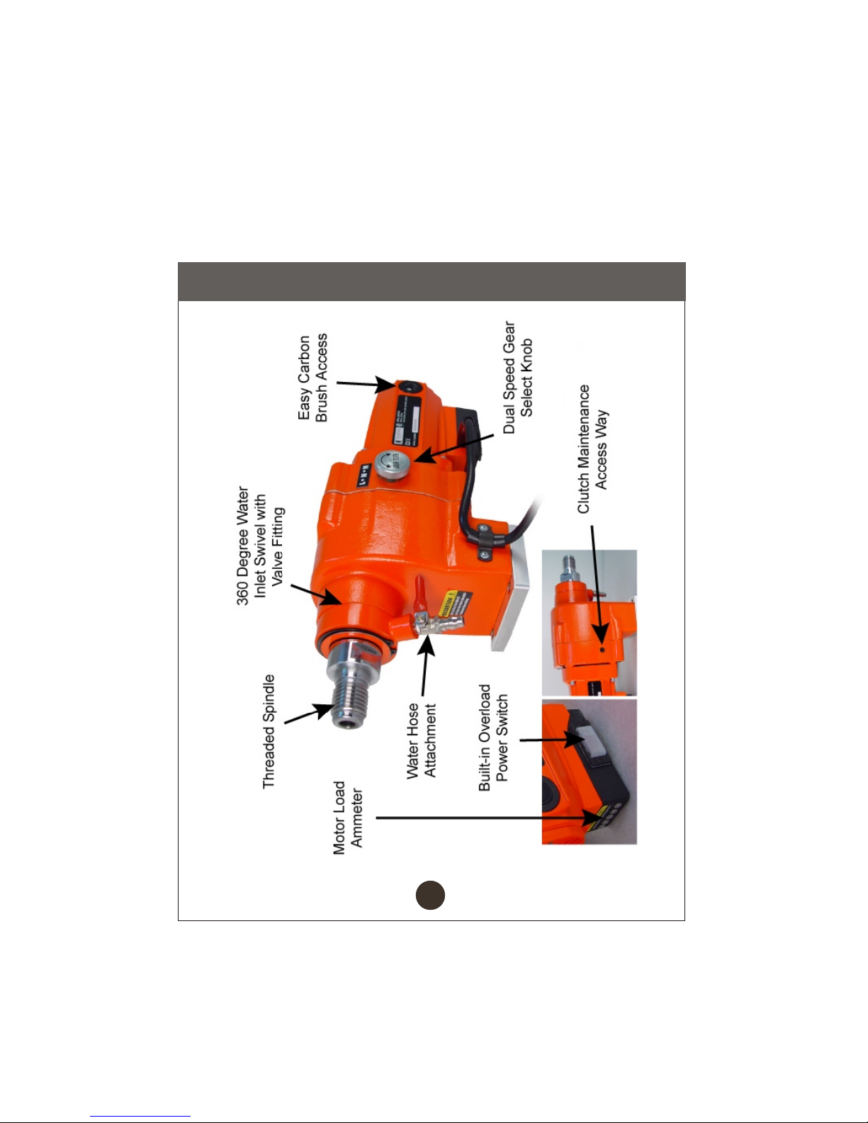
FEATURES
8

Model
Spec
VOLTAGE
POWER
SPEED
PHASE
APPLICABLE
BIT DIAMETER
WEIGHT
CB700
115V (60Hz)
3HP (2.2kW), 20A
600 ~ 1200 RPM
1" (25MM) ~ 8" (203MM)
48 LBS (21.8 KG)
SPECIFICATIONS
1
9

OPERATION
1. Coring Operation
A. Place water collecting ring in place as necessary.
B. Make sure the drill stand is properly secured to the work surface. If not
follow the instructions provided in the drill stand manual.
C. Check that the spindle speed is at the correct setting. If not adjust as
instructed in the “setup” section.
NOTE: The motor must be OFF and the spindle must not be in motion when
changing the speed setting. Failure to follow these conditions can result in gear
or motor damage.
D. Turn the water valve on the drill motor on. There must be sufficient flow of
water to the core bit.
E. Activate the drill and allow the spindle to achieve peak RPM before letting
the bit engage the work surface.
F. During the initial portion of the coring process, the bit may wander. Apply a
light amount of force at first until the bit appears to have cored out a groove.
G. While coring do not apply too much downward force. Refer to the motor
load ammeter as reference. To achieve constant even and sufficient force, keep
the yellow LED lit. Do not allow the red LED to become lit.
WARNING: Warning do not core upwards!
10

H. When the coring process is complete, the material removed or inner core
may become lodged inside the bit. Leave the drill running and raise the drill from
the work surface.
I. Turn off the drill and turn the water valve on the drill motor off.
11

MAINTENANCE
1. General Rules
A. Always clean the machine before performing any maintenance/repair.
B. A clean machine makes visual inspection for problems easier to notice.
2. Steps to Follow When Cleaning
A. Please do not use aggressive cleaners (i.e. containing solvents). Do not use
high-pressure water jets, aggressive detergents or solutions and liquids with a
temperature exceeding 86ºF! Use a fluff-free cloth only.
B. For the sake of safety, no water/cleaning liquid/vapor may penetrate into the
electric motor, connectors/plugs, switches, etc. Cover all apertures, holes in the
housing, connectors or plugs, etc. or seal them with adhesive tape!
C. Use a cloth which may be lightly moistened only for removing dust and dirt.
Hard packed dirt can be removed with a soft brush.
D. After cleaning, remove all covers and adhesive tape! All screws/nuts which
you may have loosened must be tightened again! After wet cleaning, try the
machine on a power outlet which is equipped with a power breaker (i.e. fault
current circuit breaker). If the fault current circuit breaker cuts the power supply,
the machine must be inspected by an authorized dealer prior to use!
WARNING: For your safety, before performing any maintenance on the drill turn
OFF the power switch and UNPLUG the power cord.
12

3. Carbon Brush Replacement
A. Unplug the drill motor before proceeding any further.
B. Locate the carbon brush caps found near the air inlet of the motor housing.
They are on opposing sides. Remove the caps using a flat screw driver. The
brushes contact leads should pop out as soon as the caps are off; if not, use the
screw driver to nudge them out.
C. When installing the new brushes, make sure they fit snuggly into the slots.
Do not modify the replacement brushes (i.e. file them down) or use non OEM
brushes, as it may damage the armature and in doing so voids the manufacturer
warranty.
D. Perform steps one through three in reverse to reinstall the caps. Note do not
over tighten the caps are they may be damaged.
4. Adjusting the Mechanical Clutch
A. Unplug the drill motor before proceeding any further.
B. If, while coring, the clutch slips when the ammeter only illuminates the green
or yellow LED indicator, then the clutch nut needs to be tightened.
C. To begin a special tool is needed to engage the clutch. Contact your nearest
authorized distributor or service center for parts.
D. Locate the four recessed socket head screws holding the gear housing
together and remove them.
13

E. Gently pull the gear housing apart. Only a small separation is needed to fit
two flat screw drivers into the housing’s gap. The screw drivers should be
inserted in opposing directions. Gently apply an even amount of force on both
tools to complete the housing separation.
F. Using the supplied open box wrench, hold the spindle in place.
G. Insert the torque wrench with a compatible clutch tool onto the gear
housing clutch nut as shown below. Rotate the wrench clockwise until the gauge
reads 20N-m
I. With the clutch nut properly tightened, reassemble the housing. To
reassemble press the two halves of the housing together. Make sure the
orientation and internal components mate correctly. Now sit the drill on the
motor’s back side so the spindle faces upwards. Using a mallet lightly tap the
housing closed. Every so often turn the spindle to guarantee the gears are
meshing together instead of interfering. Force must be distributed evenly
around the housing to keep the two halves level as they come together.
J. Reattach the four screws to complete the gear housing assembly.
.
14
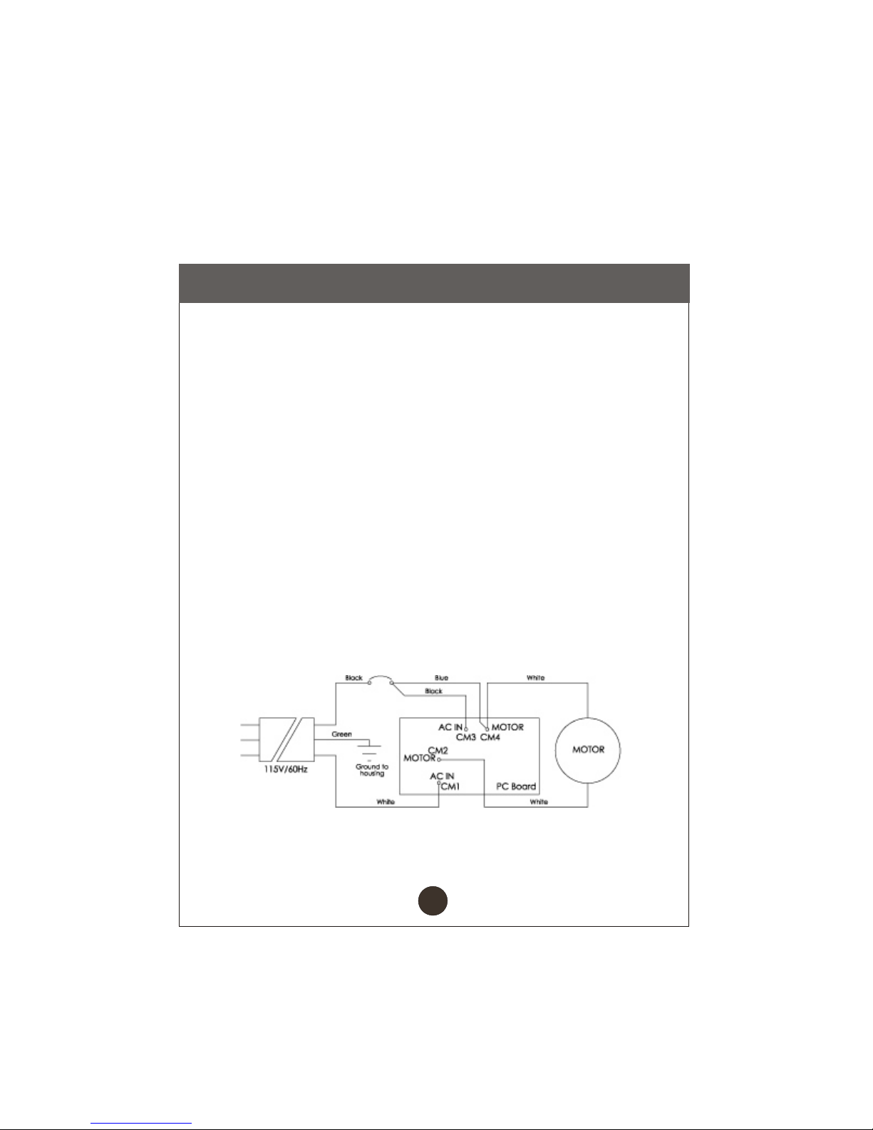
WIRING DIAGRAM
1. Electrical Specifications:
3HP (2.2kW)
115V
20A
600~1200 RPM
60Hz
1 Phase
2. Recommendations
A. It is recommended that a 20 amp circuit be used while operating this drill
machine. This will prevent any loss of power or interruption.
B. Always plug the motor as close as possible to the power source while
operating. This will allow you to receive optimum electricity.
3. Electrical Wiring Diagram
15

TROUBLESHOOTING
Problem: Bit is jammed while coring.
Possible Cause: Debris is lodged between core and bit.
Solution: Rotate bit in both directions using spanner to release
debris then inspect bit.
Possible Cause: Drill stand is not secured to work surface.
Solution: Reset base and secure properly using vacuum base or
anchor.
Possible Cause: Diamond rims have worn away.
Solution: Replace core bit.
Problem: Coring speed has reduced.
Possible Cause: Bit has encountered rebar.
Solution: Adjust feed pressure to avoid motor overload.
Possible Cause: Diamonds have glazed over.
Solution: Dress diamond rim on bit and check water feed rate.
Possible Cause: Diamond rims have worn away.
Solution: Replace core bit.
Possible Cause: New core bit.
Solution: Core at a slow rate during first 2-3 coring cycles.
Problem: Core bit appears to sway.
Possible Cause: Shaft was been damaged.
Solution: Replace shaft and check bearing arrangement.
Possible Cause: Bit is deformed or damaged.
Solution: Replace core bit.
Possible Cause: Chips are attaching to the bit.
Solution: Inspect core bit and increase water flow rate.
16
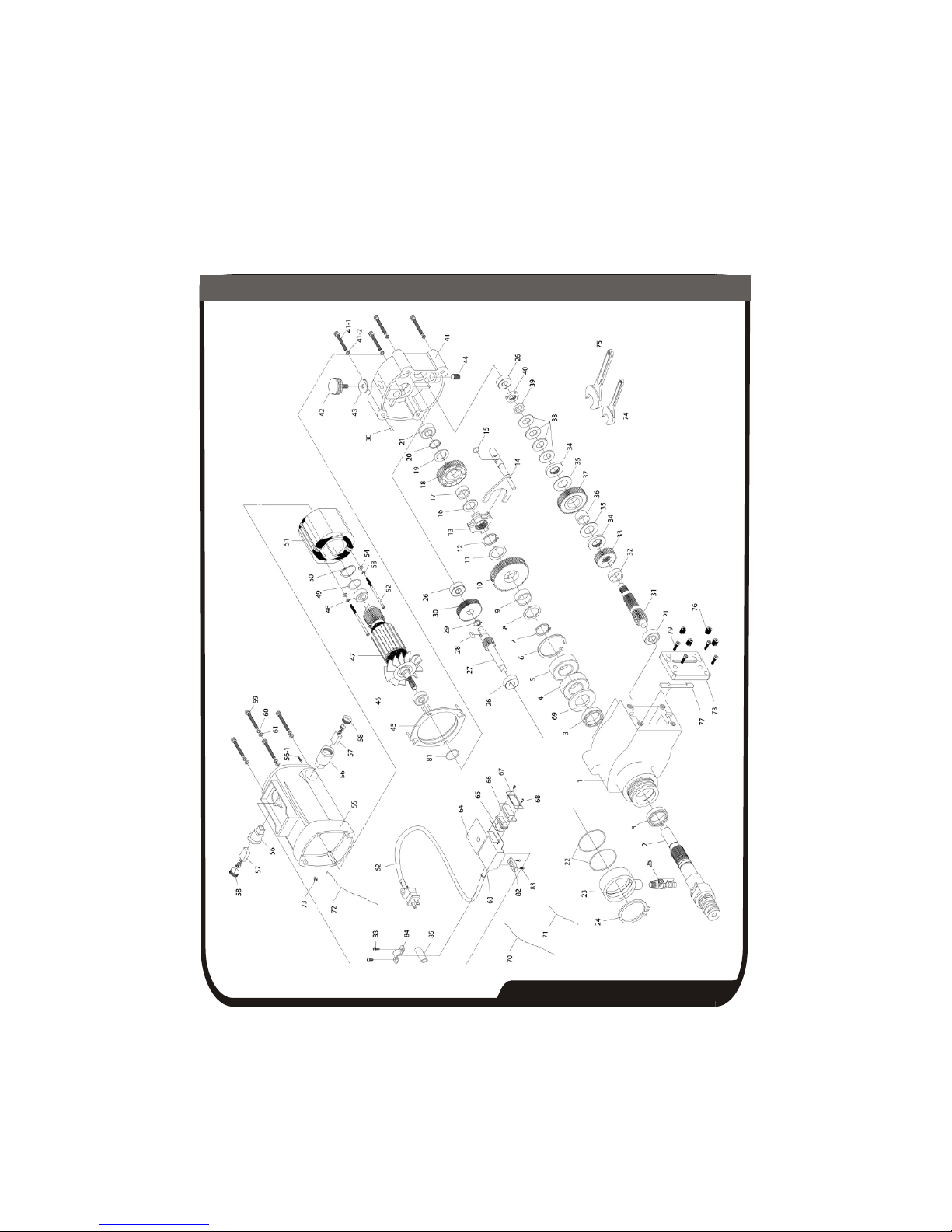
CB700
EXPLODED VIEW
PARTS LIST
CB700
Gear case
Main shaft
Bearing 6206ZZ/C2
Bearing 6206LLU
Snap ring R62
Snap ring S30
Metal collar
Brass collar 35x29x12
First gear
Metal collar
Snap ring S28
Shift ring
Shift lever
O-ring
Metal collar
Brass collar 28x22x9
Second gear
Metal collar
Snap ring S22
Bearing 6202Z
O-ring 60x2.0
Water supply cover
Snap ring S63
Water cock
Bearing 6201Z
First pinion
Woodruff key 5x5x12
Snap ring
Third gear
Seal 48x34x8
ITEM# QTY PART NO.
1
2
3
4
5
6
7
8
9
10
11
12
13
14
15
16
17
18
19
20
21
22
23
24
25
26
27
28
29
30
1
1
2
1
1
1
1
2
1
1
1
1
1
1
1
2
1
1
1
1
2
2
1
1
1
3
1
1
1
1
6063050
6063051
6063052
6063053
6063054
6063055
6063056
6063057
6063058
6063059
6063060
6063061
6063062
6063063
6063064
6063065
6063066
6063067
6063068
6063069
6063070
6063071
6063072
6063073
6063074
6063075
6063076
6063077
6063078
6063079

PARTS LIST
CB700
Second pinion
Metal collar
Forth gear
Plate
Friction plate
Brass collar
Fifth gear
Disk spring 35.2x18.3x2.0
Metal collar 5T
Fine U-nut
Diaphragm
Socket head cap screw
M8x1.25x60L
Spring washer
M8 ODx13.6 ODx1.8T
Speed change knob
Rubber washer
Plug
Baffle
Bearing 6201LLU
Armature
Bearing 6200ZZ
Filling ring 6200
O-ring
Field
Round head phillip screw -
cone point M5x85
Spring washer 5MM
Flat washer 5MM
Motor house
ITEM# QTY PART NO.
31
32
33
34
35
36
37
38
39
40
41
41-1
41-2
42
43
44
45
46
47
48
49
50
51
52
53
54
55
1
1
1
1
1
1
1
4
1
1
1
4
4
1
1
1
1
1
1
1
1
1
1
2
2
2
1
6063080
6063081
6063082
6063083
6063084
6063085
6063086
6063087
6063088
6063089
6063090
6063091
6063092
6063093
6063094
6063095
6063096
6063097
6063098
6063099
6063100
6063101
6063102
6063103
6063104
6063105
6063106
Table of contents
Other Diamond Products Drill manuals


