Diamond Products CPG200 User manual

FLOOR GRINDER
OPERATOR’S MANUAL
CPG200
Dual Head Floor Grinder
December, 2019
Part #: 1802710


TABLE OF CONTENTS
Table of Contents
Introduction ............................................................................................................................................. 5
CPG200 Components (10 HP Gas) ........................................................................................................ 6
CPG200 Components (2 HP Electric) .................................................................................................... 7
CPG200 Components (7-1/2 HP Electric) .............................................................................................. 8
CPG200 Dimensions .............................................................................................................................. 9
CPG200 Specifications ......................................................................................................................... 10
CPG200 Electric Motor Specifications .................................................................................................. 11
CPG200 Gas Engine Specifications ..................................................................................................... 11
Safety ................................................................................................................................................... 12
Safety Alerts ...................................................................................................................................... 12
Proposition 65 ................................................................................................................................... 12
Respiratory Hazards ......................................................................................................................... 12
General Safety .................................................................................................................................. 13
Grinding Safety ................................................................................................................................. 14
Belt Safety ......................................................................................................................................... 14
Transporting Safety ........................................................................................................................... 14
Lifting Safety ..................................................................................................................................... 14
Operating .............................................................................................................................................. 15
General Operating Precautions ......................................................................................................... 15
Handlebar .......................................................................................................................................... 15
Handlebar ...................................................................................................................................... 15
Adjusting the Handlebar ................................................................................................................ 15
Rear Axle .......................................................................................................................................... 15
Distributing the Weight for Grinding Operations ............................................................................ 16
Distributing the Weight to Move the Grinder ..................................................................................
16
Diamond Grinding Head .................................................................................................................... 16
Inspecting the Grinding Head ........................................................................................................ 16
Installing the Grinding Head .......................................................................................................... 16
Removing the Grinding Head ........................................................................................................ 17
Motors ............................................................................................................................................... 17
CPG202E-1 ................................................................................................................................... 17
CPG275E-1 ................................................................................................................................... 17
CPG275E-3 ................................................................................................................................... 18
Starting the Motor .......................................................................................................................... 18
Stopping the Motor ........................................................................................................................ 18
Engines ............................................................................................................................................. 18
Starting the Honda engine ............................................................................................................. 19
Stopping the Honda engine ........................................................................................................... 19
Vacuum Port ..................................................................................................................................... 20
Water Supply ..................................................................................................................................... 20
Grinding ............................................................................................................................................. 20
Tasks Prior to Grinding .................................................................................................................. 20
Dry Grinding .................................................................................................................................. 20
Wet Grinding.................................................................................................................................. 21
Maintenance ......................................................................................................................................... 22
General ............................................................................................................................................. 22
Pre Maintenance Preparations .......................................................................................................... 22
General Cleaning .............................................................................................................................. 22
Cleaning Techniques ..................................................................................................................... 22
Starter or Switch Box ..................................................................................................................... 22

TABLE OF CONTENTS
Motor ............................................................................................................................................. 22
Part Lubrication ................................................................................................................................. 22
Post Cleaning .................................................................................................................................... 22
Service Schedule .................................................................................................................................. 23
Daily Service ......................................................................................................................................... 24
Check Engine Oil Level ..................................................................................................................... 24
Check Engine Fuel Level .................................................................................................................. 24
Check the Air Filter ............................................................................................................................ 24
Handlebar .......................................................................................................................................... 24
Lubricate the Blade Shaft and Gear Shaft Bearings ......................................................................... 24
Inspect the Drive Belts ...................................................................................................................... 24
Drive Belt Access .......................................................................................................................... 24
Belt Tensioning ................................................................................................................................. 25
Tensioning the Drive Belts (Electric Motors) ................................................................................. 25
Tensioning the Drive Belts (Gas Engine) ...................................................................................... 25
Replacing the Drive Belts .............................................................................................................. 26
50 Hour Service .................................................................................................................................... 26
Clean the Air Filter ............................................................................................................................ 26
100 Hour Service .................................................................................................................................. 26
Replace the Engine Oil ..................................................................................................................... 26
Check and Adjust the Spark Plug ..................................................................................................... 26
Yearly Service....................................................................................................................................... 26
Replace Air Filter (Paper Element) ................................................................................................... 26
Replace the Spark Plug .................................................................................................................... 26
General Motor and Engine Service ....................................................................................................... 26
Draining the Fuel Tank and Carburetor ............................................................................................ 26
Disconnecting the Power to the Motor .................................................................................................. 26
Lifting .................................................................................................................................................... 26
Transport .............................................................................................................................................. 27
Prior to Transport .............................................................................................................................. 27
Transport ........................................................................................................................................... 27
Storage ................................................................................................................................................. 27
Disposal ................................................................................................................................................ 27
Appendix A ........................................................................................................................................... 30
Troubleshooting ................................................................................................................................ 30
Appendix B ........................................................................................................................................... 31
Belt Tension Specifications ............................................................................................................... 31
Power Cord Specifications ................................................................................................................ 32
Appendix C ........................................................................................................................................... 33
Additional Resources ........................................................................................................................ 33
Appendix D ........................................................................................................................................... 34
Model and Serial Numbers ................................................................................................................ 34

INTRODUCTION
Introduction
Welcome to the Diamond Products family and thank you for choosing Diamond Products equipment.
At Diamond Products we are driven to ensure you are completely satisfied with your product and
continually strive to improve our product line so that we can offer you the best possible equipment in
the industry.
This operator’s manual is a critical document that provides pertinent information regarding the safety,
operation, maintenance, and care of your new equipment. Keep this manual available at all times.
Operate the equipment and all of its components according to this manual. Failure to comply with and
understand the following safety, operation and maintenance instructions can result in serious injuries
and/or death. All operators must be properly trained or supervised by experienced personnel prior to
using this floor grinder and should understand the risks and hazards involved. Diamond Products
discourages improper or unintended equipment usage and cannot be held liable for any resulting
damages.
Equipment modifications should be made by Diamond Products to ensure safety and design. Any
modifications made by the owner(s) are not the responsibility of Diamond Products and void all
equipment warranties if a problem arises as a result of the modification.
Refer to the Diamond Products Parts List for additional information and part diagrams. Refer to the
motor/engine manufacturer as the primary source for all safety, operations, and maintenance
instructions regarding the motor/engine. Prior to operating, record the floor grinder’s serial number,
and the motor/engine model and serial numbers in Appendix D.
5

INTRODUCTION
CPG200 Components (10 HP Gas)
1. Front Guard
2. Weight Box
3. Weight
4. Honda Engine, 10 HP
5. Handlebar Locking Pins
6. Throttle
7. Handlebar
8. Water Supply Connection
9. Water Supply Valve
10. Fuel Tank
11. Oil Drain Hose
12. Vacuum Attachment Port
13. Foot Lever
14. Shaft/Coupling Assembly
6

INTRODUCTION
CPG200 Components (2 HP Electric)
1. Front Guard
2. Weight Box
3. Weight
4. Baldor Motor, 2 HP
5. Motor Control Switchbox
6. Handlebar Locking Pins
7. Handlebar
8. Water Supply Connection
9. Water Supply Valve
10. Vacuum Attachment Port
11. Foot Lever
12. Shaft/Coupling Assembly
7

INTRODUCTION
CPG200 Components (7-1/2 HP Electric)
1. Front Guard
2. Weight Box
3. Weight
4. Baldor Motor, 7-1/2 HP
5. Motor Starter Box
6. Handlebar Locking Pins
7. Handlebar
8. Water Supply Connection
9. Water Supply Valve
10. Vacuum Attachment Port
11. Foot Lever
12. Shaft/Coupling Assembly
8

INTRODUCTION
CPG200 Dimensions
CPG200 Dimensions Inches Millimeters
A Grinder Length 57-3/8 1457
B Grinder Height – Min. (Handlebar in lower position) 41-1/2 1054
Grinder Height – Max. (Handlebar in upper position) 44-1/2 1130
C Weight Box Height 30-1/8 765
D Wheel Height 10 254
E Grinder Width 27 686
F Handlebar Width 16 406
G Wheel to Blade Shaft Length 19 483
H Wheel to Spindle Length 24-1/4 616
9

INTRODUCTION
CPG200 Specifications
Grinder Model CPG210H CPG202E1 CPG275E1 CPG275E3
Grinding Head
Capacity (2) 10” / (2) 12”
Grinding Head
Speed1 550 rpm 205 rpm 530 rpm 540 rpm
Lubrication
Type NLGI #1 lithium synthetic grease
Shaft Size 1” Diameter
Shaft Bearings (3) 1” flange block bearings
Blade Shaft
Drive (2) V-Belt 4L-400 (2) V-Belt 4L-420 (3) V-Belt 4L-400
Grinding Head
Raise and
Lower
Mechanical spring loaded foot pedal
Rear Axle Size 1” OD straight
Rear Wheels (2) 10” x 2” x 3/4" (Internal bearings)
Handle Bar
Adjustment Two vertical height level options, 3” range
1. Theoretical speed. Actual speeds will vary.
10

INTRODUCTION
CPG200 Electric Motor Specifications
Grinder Model CPG202E1 CPG275E1 CPG275E3
Motor Model 35U782T988G1 L3709T CEM3709T
Rated Output Power 2 HP 7.5 HP 7.5 HP
Rated Speed 1725 rpm (Baldor
rating)
3450 rpm (Baldor
rating)
3520 rpm (Baldor
rating)
Rated Voltage 115/230 V 230 V 230/460 V
Full Load Amps 17.6/8.8 A 33 18/9
Rated Frequency 60 Hz.
Phase 1 1 3
CPG200 Gas Engine Specifications
Saw Model CPG210H
Engine Model Honda (GXV390)
Rated Output Power 10.2 HP @3600 rpm
Fuel Type Gas (87 Octane)
Fuel Tank .55 Gal. (2.1 Liters)
Engine Oil SAE 10W-30
Engine Oil Capacity 1.2 Qt. (1.1 Liters)
Safety Alert Low oil level alert (buzzer)
11
SAFETY PRECAUTIONS
Safety
Operate the equipment and all of its
components according to this manual. Failure
to comply with and understand the following
safety, operation and maintenance instructions
can result in serious injuries and/or death. All
operators must be properly trained or
supervised by experienced personnel prior to
using this floor grinder and should understand
the risks and hazards involved. Diamond
Products discourages improper or unintended
equipment usage and cannot be held liable for
any resulting damages.
Equipment modifications should be made by
Diamond Products to ensure safety and
design. Any modifications made by the
owner(s) are not the responsibility of Diamond
Products and void all equipment warranties if a
problem arises as a result of the modification.
Refer to the Diamond Products Parts List for
additional information and part diagrams. Refer
to the motor manufacturer as the primary
source for all safety, operations, and
maintenance instructions regarding the motor.
Prior to operating, record the floor grinder’s
serial number, and the motor’s model and
serial numbers in Appendix D.
Notice: The information in this manual may
be updated at any time!
Safety Alerts
DANGER
Serious injuries and/or death will occur if
these instructions are not followed.
WARNING
Serious injuries and/or death could occur if
these instructions are not followed.
CAUTION
Mild and/or moderate injuries could occur if
these instructions are not followed.
Proposition 65
PROPOSITION 65
WARNING: Concrete cutting
produces dust that can expose
you to chemicals including
Silica, crystalline (airborne
particles of respirable size),
which is known to the state of
California to cause cancer. For
more information go to:
WWW.P65WARNINGS.CA.GOV
Respiratory Hazards
WARNING
Concrete cutting produces dust and fumes
known to cause illness, death, respiratory
disease, birth defects, and/or other
reproductive harm. Safety protection
techniques include, but are not limited to:
• Wearing gloves.
• Wearing safety goggles or a face
shield.
• Using approved respirators.
• Washing work clothes daily.
• Using water when wet cutting to
minimize dust.
• Washing the hands and face prior to
eating/drinking.
For additional safety and self-protection
information contact your employer, the
Occupational Safety and Health
Administration (OSHA), and/or The National
Institute for Occupational Safety and Health
(NIOSH).
12

SAFETY PRECAUTIONS
General Safety
• Read and understand all safety,
operations, and maintenance instructions
provided in this manual prior to operating or
servicing the floor grinder.
• Keep equipment components clean and
free of slurry, concrete dust, and debris.
• Inspect water hoses prior to operating the
equipment. Clean, repair, or replace
damaged components.
• Repair the equipment immediately when a
problem arises.
• Replace equipment decals if unreadable.
• Dispose of all hazardous waste materials
according to city, state, and federal
regulations.
• Always have a phone nearby, and locate
the nearest fire extinguisher and first aid kit
prior to operating the equipment.
• Operate the equipment wearing flame
resistant clothing.
• Underage or non-trained personnel should
not operate the equipment.
• Keep all body parts away from rotating
machinery.
• Replace all guards and access panels
(unless stated otherwise) prior to operating
the equipment.
DO NOT:
• Assume the equipment will remain still
when parking/stopping the equipment on a
slope. Chock the wheels to help prevent
unnecessary movement.
• Drop equipment, supplies, tools, etc., when
handling to help prevent injuries.
• Lift and carry equipment, supplies, tools,
etc., that are too heavy and/or cannot be
lifted easily.
• Operate the equipment without using the
appropriate safety equipment required
for the work task.
• Operate or service the equipment with any
clothing, hair, or accessories that can snag
in the machinery, which could lead to
serious injuries or death!
• Operate the equipment using attachments
not associated with or recommended for
the equipment.
• Operate the equipment around combustible
materials.
• Operate the equipment with anyone near
the work area.
• Operate the equipment until all
unnecessary materials have been removed
from the work area.
• Operate the equipment with loose nuts,
screws, and bolts.
• Operate the equipment when ill or fatigued.
• Operate the equipment under the influence
of drugs and/or alcohol.
• Operate the equipment on steep slopes.
• Grease the equipment with the motor
running.
• Touch hot components when operating the
equipment.
• Leave the equipment unattended until the
motor is off and the blade has stopped.
• Place the equipment into storage until it
has cooled down.
• Service the equipment until it has cooled
down.
• Service the equipment with the motor
running.
13

SAFETY PRECAUTIONS
Grinding Safety
• The direct work area should not contain
buried or embedded electrical, gas, or
water lines that could be damaged and/or
cause personal injury while grinding.
• Turn off all electricity, gas, and water
around the direct work area prior to
grinding.
• Inspect the work area to ensure nothing will
impede full control of the machine at all
times.
• DO NOT allow any person, animal, and/or
objects in and around the work area while
grinding.
• Ensure the work area is adequately
illuminated to ensure safe operation of the
machine.
• Disconnect power when not in use, before
servicing, and when changing the grinding
head.
Belt Safety
• Turn off the motor and let the belts cool
down prior to servicing them.
• Regularly inspect the belts for fraying,
stress cracks, and/or breakage and replace
immediately when damaged. Always check
the belts alignment prior to operating the
equipment.
• Use extreme caution when working with
belts and rotating machine parts to avoid
entanglement.
• Over-tensioning the belts may reduce the
life of the blade shaft bearings. Under-
tensioning the belts may cause slippage,
shorter belt life, and/or poor equipment
performance.
• Squealing belts indicate looseness.
Transporting Safety
• Remove the grinding head prior to
transporting the equipment.
• Chock the wheels and secure the floor
grinder in the truck/trailer prior to
transporting.
• Ensure the grinding head does not make
contact with the ground and/or other surface
when transporting the floor grinder.
• Refer to the Department of Transportation
(DOT) for additional transportation
recommendations.
Lifting Safety
• Move yourself and all others
away from the lifting area when
hoisting the floor grinder to
prevent being crushed.
• DO NOT attempt to lift the floor grinder
irresponsibly and/or improperly.
14

OPERATING
Operating
General Operating Precautions
• Prior to operating the machine, read the
operator’s manual thoroughly and ensure
that you understand the safe and proper
operation of the machine.
• Use approved personal protective
equipment at all times while operating the
machine.
• Ensure that there is firefighting equipment
and a first aid kit nearby while operating the
machine.
• Ensure the grinding area is free of
obstructions, people, and or animals prior
to operating the machine.
• Always operate the machine from the
operator’s position at the rear of the
machine.
• Ensure that the proper grinding head is
used for the application.
Handlebar
The handlebar helps the operator guide and
maneuver the floor grinder. It is important to
have the handlebar set to a comfortable
working height. There are two height settings
for the floor grinder. The lower setting will set
the handlebar at a height of 41-1/2” and the
upper setting will place it at 44-1/2”.
Handlebar
Adjusting the Handlebar
1. Pull out the two T-handle locking pins from
the handlebar support tubes.
T-Handle Locking Pins
2. Adjust the handlebar up or down to the
desired working height.
3. Align the holes in the handlebar with the
hole in the support tube and reinsert the
two T-handle locking pins into the
handlebar support tube to secure.
Rear Axle
The rear axle assembly on the CPG200 is
designed to allow the rear wheels to pivot
either in front or behind the axle. This
distributes the weight to the front, for grinding
operations, or the rear, to allow the grinder to
easily be moved.
There are a set of four horizontal holes located
on the side of the grinder frame base. These
holes allow the operator to locate the axle
forward for less weight on the grinding discs or
farther back to allow more weight on the
grinding discs.
Axle Hole Locations
15
OPERATING
Additionally, each grinder has a standard 65
pound weight with an option for one more that
can be used to add more weight over the
grinding discs.
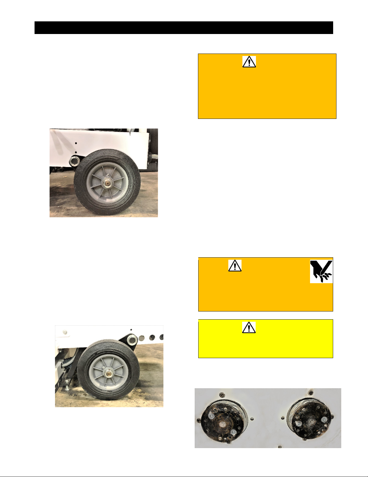
Distributing the Weight for Grinding Operations
1. Lift up on the handlebar to raise the rear
wheels off of the ground.
2. Slowly lower the grinder back down while
pushing forward to allow the rear wheels to
pivot behind the rear axle.
Rear Wheel Pivoted Back
Distributing the Weight to Move the Grinder
1. Lift up on the handlebar to raise the rear
wheels off of the ground.
2. Slowly lower the grinder back down while
pulling backward to allow the rear wheels
to pivot in front of the rear axle.
3. Once the rear wheels are pivoted in front of
the rear axle, push down on the handlebar
to raise the front of the grinder off of the
ground. This allows the operator to
manually move the grinder from one
location to another location.
Rear Wheels Pivoted Forward
Diamond Grinding Head
WARNING
• DO NOT use damaged grinding heads
when grinding to avoid harming yourself,
others, or the floor grinder.
• Always use an appropriate type of
grinding head based on the type of
material being ground.
Using the proper grinding head preserves the
grinding head and improves grinding and
operator efficiency, resulting in lower costs.
Inspecting the Grinding Head
Inspect each grinding head prior to installation
and discard all damaged grinding heads.
Inspect all grinding heads for:
• Cracks, nicks, and dents
• A damaged and/or deformed arbor (center
hole)
• A deformed blade circumference
• Segment loss and/or segment cracks
• Core wear
• Bending
Installing the Grinding Head
WARNING
• DO NOT install a grinding
head with the motor/engine
running. Failure to properly secure the
grinding head may cause parts to
loosen or fall off the saw.
CAUTION
• Wear gloves and be alert to the
surrounding environment when
handling grinding heads.
1. Using a hoist, raise the floor grinder high
enough to expose the two disc mounting
flanges.
Disc Mounting Flanges
16

OPERATING
2. With the disc mounting flanges exposed,
place a grinding head onto a flange and
align the four bolt holes.
3. Attach the grinding head to the flange by
installing four 3/8”-16 x 1” flat head cap
screws through the grinding head into the
disc mounting flange and tighten to secure.
Grinding Head Bolts
4. Repeat steps 2 and 3 with the second
grinding head.
5. Lower the floor grinder back down to the
ground.
Removing the Grinding Head
CAUTION
• DO NOT remove a grinding head with
the motor/engine running.
1. Using a hoist, raise the floor grinder high
enough to expose the two disc mounting
flanges.
2. Remove the four 3/8-16” x 1” flat heat cap
screws attaching each grinding head to the
disc mounting flanges and remove the
grinding heads.
3. Lower the floor grinder back down to the
ground.
Motors
There are three electric motors associated with
the CPG200 series floor grinders.
CPG202E-1
The CPG202E-1 floor grinder uses a 2 HP,
115/230 V, single phase electric motor rated at
1725 RPM.
The motor is controlled through a switch box
assembly. The switch box allows the operator
to start and stop the motor.
Switch Box (CPG202E-1)
The motor is protected by a thermal overload.
In the event that the motor overheats, the
thermal protector circuit will open shutting the
motor off. If this occurs, turn the motor control
switch to OFF and allow the motor time to cool.
When the motor has cooled, press the reset
button located on the motor. A click indicates
that the motor is reset and can now be
restarted.
Motor Reset Button
CPG275E-1
The CPG275E-1 floor grinder uses a 7-1/2 HP,
230 V, single phase electric motor rated at
3450 RPM.
The motor is controlled through a starter box
assembly. The starter box allows the operator
to start and stop the motor.
17

OPERATING
Starter Box Assembly
The motor is protected by a current overload
relay. In the event of an over current condition,
the overload relay will shut the motor off. If this
occurs, press the STOP button down on the
starter box top and allow the motor to cool
down. Remove the top of the starter box and
press the blue RESET button down on the
overload relay. Reinstall the starter box top
and pull up while turning clockwise on the
STOP button to reset. Press the START button
to restart the motor.
CPG275E-3
The CPG275E-3 floor grinder uses a 7-1/2 HP,
230/460 V, three phase electric motor rated at
3520 RPM.
The motor is controlled through a starter box
assembly. The starter box allows the operator
to start and stop the motor.
The motor is protected by a current overload
relay. In the event of an over current condition,
the overload relay will shut the motor off. If this
occurs, press the STOP button down on starter
box top and allow the motor to cool down.
Remove the top of the starter box and press
the blue RESET button down on the overload
relay. Reinstall the starter box top and pull up
while turning clockwise on the STOP button to
reset. Press the START button to restart the
motor.
Starting the Motor
WARNING
DO NOT leave the saw unattended while the
motor is running.
1. Ensure the grinding head is disengaged
from the floor by putting the foot lever into
the lower position.
Foot Lever –Disengaged (Lower) Position
2. Connect the floor grinder to a power source
using a properly sized power cord in
accordance with Appendix B.
CAUTION
Use of a wire gauge that is too small will
cause loss of power or overheating and will
damage the electric motor
3. When operating the 2 HP motor, move the
starter switch to the ON position on the
switch box. When operating a 7-1/2 HP
motor, press the START button on the
starter box assembly.
4. Allow the motor to come up to full operating
speed.
Stopping the Motor
CAUTION
DO NOT leave the grinder unattended until
the motor is off and the grinding head
has stopped spinning.
1. When operating the 2 HP motor, move the
starter switch to the OFF position on the
switch box. When operating a 7-1/2 HP
motor, press the STOP button on the
starter box assembly.
2. Maintain contact between the grinding
head and the ground until the grinding
head comes to a full stop.
3. Disconnect the floor grinder from the power
source.
Engines
The CPG210H floor grinder uses a 10 HP, gas
engine rated at 3600 RPM.
18

OPERATING
The engine is controlled by a throttle control
lever located on the handlebar of the machine.
The control valve allows for starting, stopping,
and adjusting engine speed.
The engine is protected by a low oil level
buzzer. The buzzer will alert the operator
when the engine needs oil. If the buzzer
sounds, stop the engine and add oil.
Starting the Honda engine
Refer to the manufacturer’s engine manual as
the primary source of information regarding the
engine.
WARNING
• DO NOT leave the saw unattended while
the engine is running.
• Always operate the saw in a well
ventilated area. Concentrated exhaust
can cause loss of consciousness and/or
death.
1. Ensure the grinding head is disengaged
from the floor by putting the foot lever into
the lower position.
Foot Lever –Disengaged (Lower) Position
2. Move the fuel valve lever to the ON
position (All the way to the right).
Fuel Valve “ON”
3. Move the control lever to the CHOKE/FAST
position.
Control Lever
NOTE: To restart a warm engine, move the
control lever slightly past the halfway point.
4. Pull the starter grip lightly until resistance is
felt, then pull briskly on the grip away from
the engine.
5. Return the starter grip gently to prevent
damage to the starter.
6. After the engine starts and has warmed up,
slowly move the choke lever back to the
desired engine speed.
Stopping the Honda engine
1. Move the control lever to the STOP/SLOW
position.
2. Move the fuel valve lever to the OFF
position (All the way to the left).
19
OPERATING
Vacuum Port
When dry grinding, it is required to have a dust
containment system used in conjunction with
the floor grinder. A dust port is located at the
back of the grinder to attach a vacuum.
Connect the vacuum to the port using a 2 inch
(50mm) hose.
Ensure that the vacuum filters are clean prior
to use and that the strip brush on the dust
guard is in contact with the ground at all times
during operation.
Dust Port
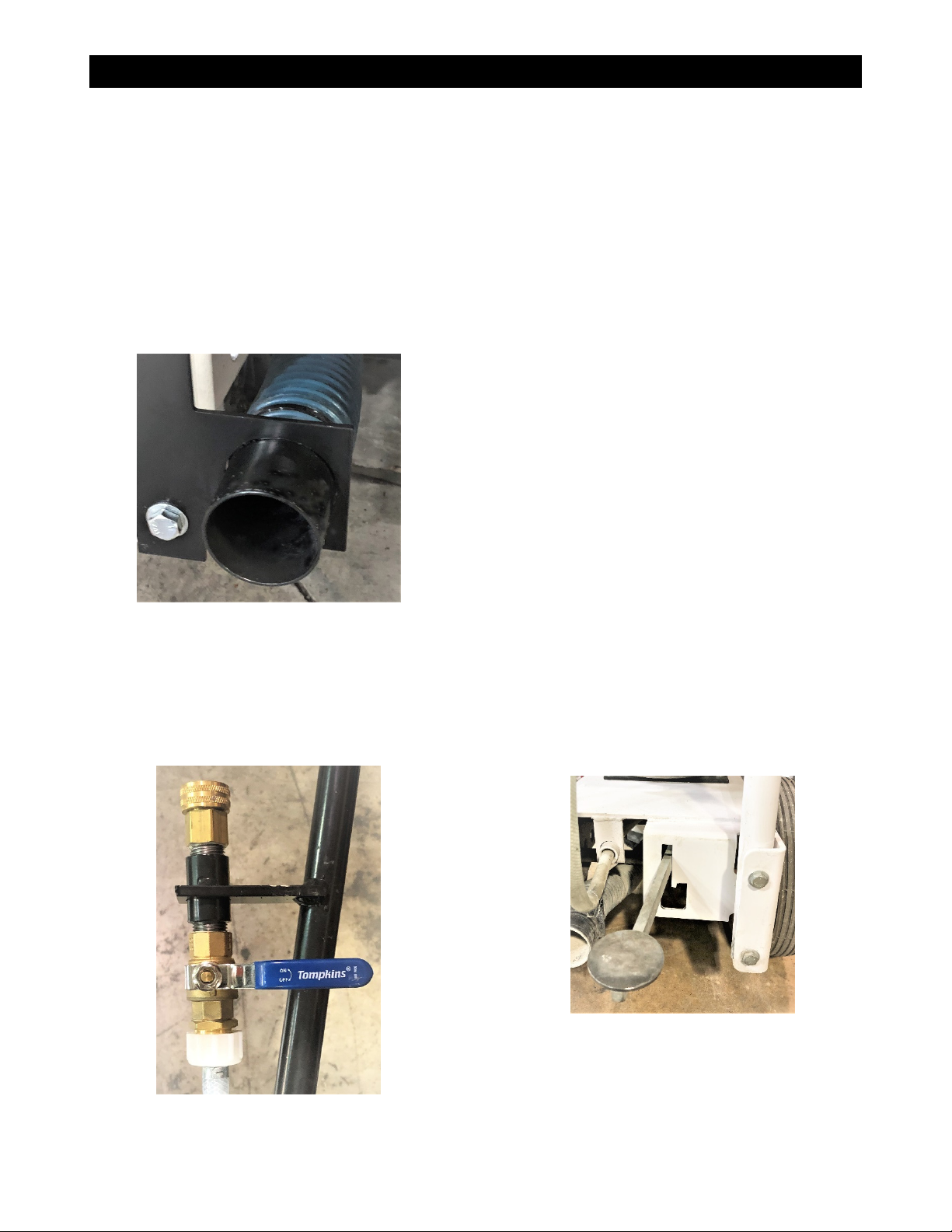
Water Supply
The floor grinder is equipped with a water
supply connection located on the left side of
the handlebar. The water is metered through
the water supply valve to the grinding head to
cool the head and minimize dust.
Water Supply Valve
Grinding
Tasks Prior to Grinding
Complete the following tasks prior to grinding
• Ensure the handlebar is securely attached
and at the desired working height.
• Inspect the grinding heads and shafts for
damage and repair or replace as required.
• Make sure that the grinding heads are
suitable for the job.
• Ensure there is a water source available if
wet grinding.
• Ensure there is an adequate dust collection
system available if dry grinding.
• Verify that the power cord is properly sized
for the job in accordance with Appendix B.
• Turn off all electricity, gas, and water
around the direct work area.
Dry Grinding
1. Connect a dust collecting vacuum system
to the dust port.
2. Start the dust collecting vacuum system in
accordance with the manufacturer’s
instructions.
3. Start the motor/engine in accordance with
the instructions provided earlier in this
section and allow the motor/engine to come
up to full operating speed.
4. Engage the grinding head by carefully
moving the foot lever into the upper
position.
Foot Lever – Engaged (Upper) Position
5. With both hands firmly on the handlebar,
move the grinder from side to side ensuring
not to stop in one spot too long as this will
lead to grooving of the surface.
NOTE: To obtain variations in grinding speed
and depth of cut, the axles can be moved
20
Table of contents
Other Diamond Products Floor Machine manuals


