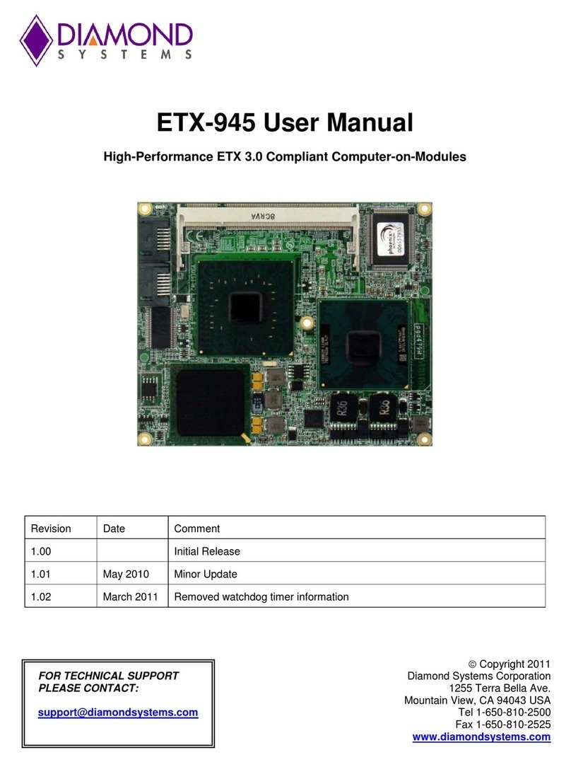
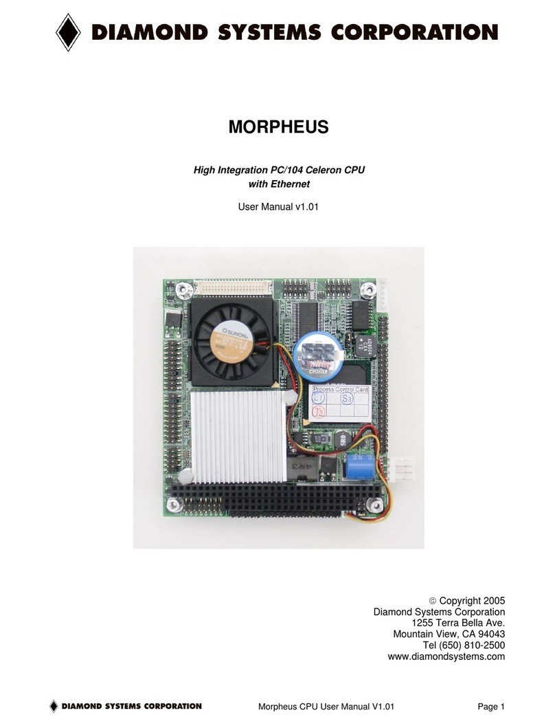
Diamond Systems SATURN SAT-E3940-4GA User manual

Saturn User Manual V1.01 www.diamondsystems.com Page 1
SATURN
PCIe/104 Expandable Single Board Computer
with Intel “Apollo Lake” E3940 Processor
FOR TECHNICAL SUPPORT Copyright 2021
PLEASE CONTACT: Diamond Systems Corporation
www.diamondsystems.com
Revision
Date
Comment
1.01
09/13/2021
Initial Release

Saturn User Manual V1 www.diamondsystems.com Page 2
CONTENTS
1Important Safe Handling Information ............................................................................................................ 4
2Introduction...................................................................................................................................................... 6
2.1 Models.......................................................................................................................................................... 6
2.2 Features........................................................................................................................................................ 6
2.3 Operating System Support........................................................................................................................... 7
2.4 Mechanical, Electrical, Environmental.......................................................................................................... 7
3Functional Overview........................................................................................................................................ 8
3.1 Block Diagram .............................................................................................................................................. 8
3.2 Feature Descriptions .................................................................................................................................... 9
3.2.1 Processor and Chipset......................................................................................................................... 9
3.2.2 Memory................................................................................................................................................ 9
3.2.3 Ethernet................................................................................................................................................ 9
3.2.4 SATA.................................................................................................................................................... 9
3.2.5 Display ................................................................................................................................................. 9
3.2.6 Audio.................................................................................................................................................... 9
3.2.7 Minicard Socket ................................................................................................................................. 10
3.2.8 USB.................................................................................................................................................... 10
3.2.9 Serial Ports ........................................................................................................................................ 10
3.2.10 Data Acquisition................................................................................................................................. 10
3.2.11 RTC Backup Battery.......................................................................................................................... 11
3.2.12 Trusted Platform Module (TPM) ........................................................................................................ 11
3.2.13 PCIe link routing................................................................................................................................. 11
3.2.14 PCIe/104 OneBank Expansion.......................................................................................................... 11
3.2.15 Utility .................................................................................................................................................. 12
3.2.16 LED Indicators ................................................................................................................................... 12
3.2.17 BIOS Features................................................................................................................................... 12
3.2.18 Power Supply..................................................................................................................................... 13
3.3 Rugged Design........................................................................................................................................... 14
4Board Mechanical Drawing........................................................................................................................... 15
5Connector and Jumper Locations ............................................................................................................... 16
6I/O Connectors............................................................................................................................................... 19
6.1 Connector Pin-out and Signal Description ................................................................................................. 19
6.1.1 Power In (J8)...................................................................................................................................... 19
6.1.2 External Battery (J7).......................................................................................................................... 19
6.1.3 Serial Ports (J9)................................................................................................................................. 19
6.1.4 USB 2.0 Ports (J10)........................................................................................................................... 20
6.1.5 LPC & Utility (J11, J12)...................................................................................................................... 21
6.1.6 Ethernet (J13, J14) ............................................................................................................................ 21
6.1.7 USB 3.0 Port (J15, J16)..................................................................................................................... 21
6.1.8 SATA (J6) .......................................................................................................................................... 22
6.1.9 Audio (J5)........................................................................................................................................... 22
6.1.10 LVDS LCD (J2).................................................................................................................................. 22
6.1.11 LCD Backlight (J24)........................................................................................................................... 23
6.1.12 HDMI (J3, J4)..................................................................................................................................... 24
6.1.13 Analog I/O (J18)................................................................................................................................. 24
6.1.14 Digital I/O (J17).................................................................................................................................. 24
6.1.15 MiniCard Socket (J20) ....................................................................................................................... 25
6.1.16 FPGA JTAG (J21).............................................................................................................................. 25
6.1.17 M.2 SATA Socket (J19) ..................................................................................................................... 26
6.1.18 Analog Circuit Calibration (J23)......................................................................................................... 26
6.1.19 PCIe/104 (J1)..................................................................................................................................... 27
6.2 List of Connectors....................................................................................................................................... 28
7I/O Cables ....................................................................................................................................................... 29
8Jumper Description....................................................................................................................................... 30
8.1 LVDS Backlight and LVDS VDD (JP1)....................................................................................................... 31
8.2 Digital IO and Address (JP2)...................................................................................................................... 31
8.3 Serial Port Configuration (JP3)................................................................................................................... 31
9BIOS Key Features (TBU).............................................................................................................................. 33
9.1 Entering the BIOS....................................................................................................................................... 33

Saturn User Manual V1 www.diamondsystems.com Page 3
9.2 Restoring Default BIOS Settings................................................................................................................ 33
9.3 Upgrading BIOS using SHELL Utility.......................................................................................................... 33
9.4 Setting the Date and Time.......................................................................................................................... 33
9.5 Boot Priority................................................................................................................................................ 34
9.6 LED............................................................................................................................................................. 34
9.7 Quiet / Quick Boot / Splash Screen............................................................................................................ 34
9.8 Serial Port Configuration ............................................................................................................................ 34
10 Getting Started............................................................................................................................................... 35
10.1 Quick Setup................................................................................................................................................ 35
10.2 Boot Device Options................................................................................................................................... 35
10.3 Installing OS and Booting........................................................................................................................... 36
11 Video Features............................................................................................................................................... 37
12 Serial Ports and System Console ................................................................................................................ 38
12.1 Configuration .............................................................................................................................................. 38
12.2 Console redirection..................................................................................................................................... 38
13 DATA ACQUISITION CIRCUIT....................................................................................................................... 39
13.1 Overview..................................................................................................................................................... 39
14 Software driver overview.............................................................................................................................. 40
15 Thermal Solution............................................................................................................................................ 41
16 Specifications................................................................................................................................................. 42

Saturn User Manual V1.01 www.diamondsystems.com Page 4
1 IMPORTANT SAFE HANDLING INFORMATION
WARNING!
ESD-Sensitive Electronic Equipment
Observe ESD-safe handling procedures when working with this product.
Always use this product in a properly grounded work area and wear appropriate
ESD-preventive clothing and/or accessories.
Always store this product in ESD-protective packaging when not in use.
Safe Handling Precautions
The Saturn SBC contains a high number of I/O connectors with connection to sensitive electronic components. This
creates many opportunities for accidental damage during handling, installation and connection to other equipment.
The list here describes common causes of failure found on boards returned to Diamond Systems for repair. This
information is provided as a source of advice to help you prevent damaging your Diamond (or any vendor’s)
embedded computer boards.
ESD damage –This type of damage is usually almost impossible to detect, because there is no visual sign of failure
or damage. The symptom is that the board eventually simply stops working, because some component becomes
defective. Usually the failure can be identified and the chip can be replaced.
To prevent ESD damage, always follow proper ESD-prevention practices when handling computer boards.
Damage during handling or storage –On some boards we have noticed physical damage from mishandling. A
common observation is that a screwdriver slipped while installing the board, causing a gouge in the PCB surface
and cutting signal traces or damaging components.
Another common observation is damaged board corners, indicating the board was dropped. This may or may not
cause damage to the circuitry, depending on what is near the corner. Most of our boards are designed with at least
25 mils clearance between the board edge and any component pad, and ground / power planes are at least 20 mils
from the edge to avoid possible shorting from this type of damage. However these design rules are not sufficient to
prevent damage in all situations.
A third cause of failure is when a metal screwdriver tip slips, or a screw drops onto the board while it is powered on,
causing a short between a power pin and a signal pin on a component. This can cause overvoltage / power supply
problems described below. To avoid this type of failure, only perform assembly operations when the system is
powered off.
Sometimes boards are stored in racks with slots that grip the edge of the board. This is a common practice for board
manufacturers. However our boards are generally very dense, and if the board has components very close to the
board edge, they can be damaged or even knocked off the board when the board tilts back in the rack. Diamond
recommends that all our boards be stored only in individual ESD-safe packaging. If multiple boards are stored
together, they should be contained in bins with dividers between boards. Do not pile boards on top of each other or
cram too many boards into a small location. This can cause damage to connector pins or fragile components.
Power supply wired backwards –Our power supplies and boards are not designed to withstand a reverse power
supply connection. This will destroy each IC that is connected to the power supply (i.e. almost all ICs). In this case
the board will most likely will be unrepairable and must be replaced. A chip destroyed by reverse power or by
excessive power will often have a visible hole on the top or show some deformation on the top surface due to
vaporization inside the package. Check twice before applying power!
Board not installed properly in PC/104 stack –A common error is to install a PC/104 board accidentally shifted
by 1 row or 1 column. If the board is installed incorrectly, it is possible for power and ground signals on the bus to
make contact with the wrong pins on the board, which can damage the board. For example, this can damage
components attached to the data bus, because it puts the 12V power supply lines directly on data bus lines.

Saturn User Manual V1 www.diamondsystems.com Page 5
Overvoltage on analog input –If a voltage applied to an analog input exceeds the design specification of the
board, the input multiplexor and/or parts behind it can be damaged. Most of our boards will withstand an erroneous
connection of up to 35V on the analog inputs, even when the board is powered off, but not all boards, and not in
all conditions.
Overvoltage on analog output –If an analog output is accidentally connected to another output signal or a power
supply voltage, the output can be damaged. On most of our boards, a short circuit to ground on an analog output
will not cause trouble.
Overvoltage on digital I/O line –If a digital I/O signal is connected to a voltage above the maximum specified
voltage, the digital circuitry can be damaged. On most of our boards the acceptable range of voltages connected to
digital I/O signals is 0-5V, and they can withstand about 0.5V beyond that (-0.5 to 5.5V) before being damaged.
However logic signals at 12V and even 24V are common, and if one of these is connected to a 5V logic chip, the
chip will be damaged, and the damage could even extend past that chip to others in the circuit.
Bent connector pins –This type of problem is often only a cosmetic issue and is easily fixed by bending the pins
back to their proper shape one at a time with needle-nose pliers. The most common cause of bent connector pins
is when a PC/104 board is pulled off the stack by rocking itback and forth left to right, from one end of the connector
to the other. As the board is rocked back and forth it pulls out suddenly, and the pins at the end get bent significantly.
The same situation can occur when pulling a ribbon cable off of a pin header. If the pins are bent too severely,
bending them back can cause them to weaken unacceptably or even break, and the connector must be replaced.

Saturn User Manual V1.01 www.diamondsystems.com Page 6
2 INTRODUCTION
SATURN is a 4.5” x 4.0” PCIe/104-expandable SBC based on Intel Apollo lake x5-E3940 processor with a
PassMark rating of approximately 1900. The board provides expansion option over minicard and PCIe/104
OneBank. It features 4GB Non-ECC/ 8GB ECC DDR3L memory soldered on board, conduction cooling, Minicard
socket, M.2 socket, two Gigabit Ethernets, multiple displays and -40 to +85C operation. The board is of 4.5x4” form
factor.
2.1 Models
Model number
Processor / speed
Cores
RAM
Data Acquisition
SAT-E3940-4GA
x5-3940 / 1.80 GHz
4
4GB Non ECC
Analog + Digital I/O
SAT-E3940-4GD
x5-3940 / 1.80 GHz
4
4GB Non ECC
Digital I/O
SAT-E3940-8GEA
x5-3940 / 1.80 GHz
4
8GB ECC
Analog + Digital I/O
SAT-E3940-8GED
x5-3940 / 1.80 GHz
4
8GB ECC
Digital I/O
2.2 Features
Processor Apollo lake,x5-3940, Quad Core, 1.6GHz, 9.5W TDP
Apollo lake,x5-3930, Dual Core, 1.3GHz, 6.5W TDP (Optional)
Apollo lake,x5-3950, Quad Core, 1.6GHz, 12W TDP (Optional)
Memory On board 8GB DDR3L ECC / 4GB non ECC
Ethernet 1 10/100/100 Mbps direct from processor using I210 PHY
1 10/100/1000 Mbps from 1:4 PCIe switch using I210 PHY
SATA 1 port, direct from processor to standard SATA connector
1 port, direct from processor to M.2 2242 connector
USB 2 USB 2.0 ports to standard header
2 USB 2.0 / USB3.0 ports to standard header
1 USB 2.0 port on Mini card socket
2 USB 2.0 ports to One Bank PCIe/104
LCD Dual channel LVDS, using eDP to LVDS Bridge
HDMI 2 ports direct from processor
Audio HD Audio with Line In, Mic In, Line Out
Serial ports 2 ports with RS232/RS422/RS485 capability

Saturn User Manual V1 www.diamondsystems.com Page 7
1 port with RS232 capability
Data Acquisition
16 16-bit analog inputs with 250KHz maximum sample rate
4 16-bit analog outputs with waveform generator
22 digital I/O lines with programmable direction (16 DIO on N models)
8 32-bit counter/timers
4 24-bit PWMs
Expansion 1 Full MiniCard socket with PCIe x1 and USB2.0
1 M.2 2242 socket with SATA
One Bank PCIe/104 with 4 PCIe x1, 2 USB2.0
2.3 Operating System Support
Windows 10 64bit, Linux 64bit
Driver packages and/or BSPs available for each OS
2.4 Mechanical, Electrical, Environmental
Form factor 4.5”W x 4.0”H / 114 x 102mm
Cooling Conduction cooling, heat spreader
Power +5VDC in
Operating Temp -40°C to +85°C at outer surface of heat spreader
Environmental Designed to meet the following conditions:
Shock: MIL-STD-202G, Method 213-B, Table 213-1 Condition A, 50G / 11ms half sine, non-
operational
Vibration: MIL-STD-202G, Method 214A, Table 214-1, Condition D, 11.95G random vibration, 15
minutes per axis, operational

Saturn User Manual V1 www.diamondsystems.com Page 9
3.2 Feature Descriptions
This section describes the key subsystems of the Saturn SBC.
3.2.1 Processor and Chipset
The Intel Atom® processor E390x series, formerly Apollo Lake, empowers real-time computing in digital
surveillance, new in-vehicle experiences, advancements in industrial and office automation, new solutions for retail
and medical, and more. These processors are based on the Goldmont architecture, utilizing Intel’s industry-leading
14 nm process technology.
Saturn SBC is based on Intel Atom processor x5-E3940. It is a quad core, 64-bit processor with a maximum
frequency of 1.8GHz.
3.2.2 Memory
The design employs DDR3L memory down configuration with ECC. The design supports single channel memory
interfaces with each up to 8GB capacity with ECC.
Channel consists of 8nos DDR3L 4Gbit chips with to support 4GB non-ECC memory and 9nos of DDR3L 8Gbit
chips with to support 8GB ECC memory configuration.
3.2.3 Ethernet
The board provides two Gigabit Ethernet ports. One port is derived directly from processor’s x1 PCIe lane using an
external I210 controller. The second port is realized from 1:4 PCIe switch lane using I210 controller. The board also
includes the necessary magnetics for both the ports. Ethernet interface is terminated on a latching connector, not
an RJ-45 jack.
On-board LEDs are provided for Link, Activity, and Speed. The LEDs are located along the board edge near the
Ethernet connector. The GbE ports use dual row,2x5 2mm pitch latching connectors. The connector does not
provide access to the LED signals.
3.2.4 SATA
The board offers two SATA ports, both derived from the processor. One port is connected to an industry-standard
vertical 7pin SATA connector that accepts cables with latching. The second port is connected to M.2 2242 size, M-
key socket. SBC provides onboard M3 2mm spacer and M3 Screw to mount M.2 2242 sata SSD.
3.2.5 Display
The board offers three display output options: two HDMI and one LVDS.
The HDMI ports are directly from the processor and are made available on two separate dual row 2x10 2mm pitch
latching connectors. Two HDMI ports support HDMI 1.4b, maximum resolution is up to 3840x2160 @ 30Hz.
LVDS interface is obtained using an eDP to LVDS converter with the NXP PTN3460. The LCD backlight control is
provided by aPWM circuit.Both single channel and Dual channel LCDs aresupported. VDDvoltage can beselected
from 5V or 3.3V and Backlight Voltage can be selected from 12V or 5V.
LCD data signals are terminated on a 2x15 1mm pitch latching while LCD Backlight control & enable signals are
terminated on a 1x6 1.25mm pitch latching connector. LVDS display supports upto1920x1200 @ 60 Hz resolution
in dual LVDS bus mode.
3.2.6 Audio
The board provides HDA compatible audio controller ALC892. Audio I/O signals include stereo line in, stereo line
out and mono mic in. The analog audio signals are made available on a dual row 2x5 2mm pitch latching connector.

Saturn User Manual V1 www.diamondsystems.com Page 10
3.2.7 Minicard Socket
The board provides expansion for one full size (51mm length) Minicard socket. The socket supports mPCIe add on
cards. Minicard interface support PCIex1 lane port and one USB2.0 port. Access to sim card signals are not
provided. If LTE modem need to be used, please select module with SIM connector.
SBC provides 2nos onboard M2 3.55mm spacer and M2 screws to mount minicard module
3.2.8 USB
The board offers seven USB 2.0 ports and two USB 3.0 ports directly from the processor.
One USB 2.0 port is connected to the Mini card socket, two are made available on dual row 2x5 2mm pitch latching
connector, and another two are available on one bank PCIe/104 connector.
USB 3.0 ports are available on 2nos of dual row, 2x5 2mm pitch latching connectors along with USB2.0 ports.The
USB3.0 and USB2.0 port mappings are as below:
USB3.0 Ports
Port Number
Port Termination
Port 0
USB3.0 Connector1
Port 1
USB3.0 Connector2
USB2.0 Ports
Port Number
Port Termination
Port 0
USB3.0 Connector1
Port 1
USB3.0 Connector2
Port 2
Mini Card Connector
Port 3
PCIe/104 Connector
Port 4
Port 5
USB2.0 Connector
Port 6
3.2.9 Serial Ports
The board provides 3 serial ports from the processor. Two serial ports support RS-232/422/485 protocols using
Exar SP336 multiprotocol transceivers. Protocol selection are controlled by FPGA gpio and configurable via
application software. TX / RX 121-ohm line termination resistors for RS-422/485 can controlled by Jumper.
One serial port supports RS232 protocol using the RS232 transceiver. In RS-232 mode, only signals TX, RX are
provided. Option for TTL level signals is provided. The RS232 port is also used as console redirection for
debug/development purposes.
The serial ports are terminated on dual row, 2x5 2mm pitch latching connectors. One such connector provides
access to two serial ports.RS232 port is made available as part of the utility connector.
3.2.10 Data Acquisition
The board provides an optional data acquisition subcircuit containing analog input, analog output, and digital I/O
features. This circuit is controlled by an FPGA attached to the processorvia the LPC bus. A pin header on the board
provides access to JTAG signals for reprogramming the FPGA on the board and in the field.
Features of the DAQ subcircuit include: 16 single-ended / 8 differential analog inputs with 16-bit resolution,
programmable input ranges, and 250KSPS maximum throughput; 4 analog outputs with 16-bit resolution and
programmable output ranges; and 22 digital I/O lines with selectable 3.3V/5V logic levels, selectable pull-up/down
resistors, programmable direction, buffered I/O, and capability for use as counter/timer and PWM circuits.

Saturn User Manual V1 www.diamondsystems.com Page 11
3.2.11 RTC Backup Battery
The RTC current consumption is 6uA with RTC voltage at 3.0V while the system is in a mechanical off (G3) state
at room temperature. This data can be used to estimate the battery life. The voltage of the battery can affect the
RTC accuracy. In general, when the battery voltage decays, the RTC accuracy also decreases
An onboard 2032 coin cell battery holder and battery are provided on the bottom side of the board, accessible
through a cutout in the heat spreader. A 1x2 connector is also provided to enable the use of an external battery for
rugged applications.
Batteries are rated by storage capacity in milli-ampere hours (mAh). The battery life can be calculated by dividing
the battery’s capacity by the average RTC current required and considering external factors that effects the battery
life. For example, if the battery storage capacity is 190 mAh (assumed usable) and the average current required is
6 μA, the ideal battery life will be: 190,000 μAh/6 μA = 31,667 h = 3.6 years.
External Battery voltage specification: Typical 3.0V; Max: 3.2V; Min: 2.0V
The board can boot and function properly without a backup battery installed.
3.2.12 Trusted Platform Module (TPM)
The board contains Infineon’s SLB 9670XQ2.0 TPM module featuring a fully TCG TPM 1.2/2.0 standard compliant
module with an SPI interface. TPM can be used as a root of trust for platform integrity, remote attestation, and
cryptographic services.
3.2.13 PCIe link routing
Apollo lake processor supports 4 PCIe 2.0 ports and 6 lanes can be allocated over those 4 ports. Bypass option is
provided for I210 Gbe Controller 2 by removing PCIe switch for the configuration where PCIe switch and PCIe/104
connector is not used.
The PCIe port mapping is as below:
PCIe Port No.
Lane Width
Port Termination
Port 1
X2
1:4 PCIe Switch
•Three x1 lanes to one bank PCIe/104 connector
•One x1 lane to I210 Gbe controller 2
Port 2
x1
I210 Gbe controller 1
Port 3
x1
One bank PCIe/104 connector Port1
Port 4
x1
Minicard socket
3.2.14 PCIe/104 OneBank Expansion
The board offers expansionover one bank PCIe/104 connector with taller 22mmstacking height to ensureclearance
over an installed minicard module on the main board.
The OneBank specification supports up to four x1 lane PCIe ports on one bank PCIe/104 connector, and all four
lanes are supported on Saturn. The PCIe lane mapping on the one bank PCIe/104 connector is as below:
PCIe Lane No.
PCIe Host
Lane 0
Directly from the processor
Lane 1
Indirectly from the processor via 1:4 PCIe switch
Lane 2
Lane 3
5V from input power connector is directly connected PCIe/104 connector so that the board can either powered by
input power connector or PCIe/104 one bank connector. Option to disconnect 3.3V to the PCIe/104 connector is
provided.

Saturn User Manual V1 www.diamondsystems.com Page 12
3.2.15 Utility
The board offers two 2x5 utility connectors, one with LPC bus interfaces for external IO expansion and another with
Serial Port (RS232), Power Button, Reset button and I2C interface.
Out of the two connectors, one provides 500mA fused 3.3V and 5V and the other connector provide 500mA fused
3.3V.
3.2.16 LED Indicators
The board provides the following LED indicators. All LEDs are located near to a board edge or their respective
features. The blue LED is located along the lower edge of the board. All LEDs are labeled in silkscreen with their
function.
PWRIN: Green LED when Input supply 5VDC is applied
PWRON: Green LED when board is powered on
BIOS: Green, connected to a GPIO line on the processor; this LED is off during power-
up and is turned on in the BIOS to indicate a successful system BIOS startup.
Ethernet: 6 Green LEDs, 1 each for Link, Activity, and Speed per port
DONE: FPGA is configured successfully.
USER: Blue, User LED, controlled by processor FPGA
3.2.17 BIOS Features
The BIOS provides the following key features:
Boot from LAN (PXE) as well as USB and SATA ports
Free boot sequence configuration to allow different boot sequences as first, second and third boot
devices
Support multi display mode. HDMI and LVDS can be active simultaneously
Console (display and keyboard) redirection to one or more COM ports
DSC-configurable default settings inbattery-less configurations; thenecessary BIOS customization tool
must be provided
Customizable splash screen
Quiet boot option
Enable/disable for individual COM ports.
LPC interface for DAQ FPGA
Wake on LAN for on-board Ethernet, minicard socket
Single BIOS to support various memory configurations and processor variants
Integrated verb table for ALC892 Audio codec
BIOS LED to indicate successful BIOS initialization
Supports standard BIOS hotkey. This includes ESC key to enter BIOS menu etc
Password protection
Field upgradeable via a Shell/Windows utility

Saturn User Manual V1 www.diamondsystems.com Page 13
3.2.18 Power Supply
The board requires only +5VDC input voltage as per the PCIe/104 Specification. It supports ACPI for pushbutton
on/off control. It supports Standby mode with an optional +5VSBinput. In standby mode, the board may be powered
on via Wake on Lan feature on at least one Ethernet port.
The 5V supply on the PCIe/104 connectors is routed directly to the input power connector, so that the board may
obtain its input power from either the input power connector or fromthe bus connector. Maximum allowablereflected
ripple, measured at the voltage input connector is 50mV p-p.
All required supply voltages for the board, are derived from the 5V input. These power supplies are sized to support
the highest power E3940 family processor with the highest capacity on-board memory plus have enough reserve
capacity to support the below add-on features:
5V 3.3V Feature
2.0A 0.5A PCIe add-on modules
1.3A PCIe Minicard add-on modules
1.5A M.2 Sata SSD
1.4A 0.7A LCD power
0.9A LCD backlight
0.05A DAQ connector
0.05A Utility connector
1.0A USB 2.0 ports x2
1.8A USB 3.0 port x2
The PCIe/104 connector obtains 5V power directly from the input connector. The +12V pin on the input power
connector is routed to the +12V source for the LCD backlight.

Saturn User Manual V1.01 www.diamondsystems.com Page 14
3.3 Rugged Design
Saturn is designed from the ground up with a comprehensive set of features to meet the challenges of rugged
environments and applications:
Memory is soldered down to avoid problems that can occur with commercial style SODIMM type
memory modules
The 50% thicker PCB increases rigidity and improves reliability of fine pitch and high-ball-count BGA
solder joints
All I/O connectors are latching for increased ruggedness
A bottom-side heat spreader provides more efficient cooling than a traditional heat sink. Processor and
memory chips are both thermally connected to the heat spreader. In addition, the exterior surface
features recessed thermal pads for improved thermal connectivity to the system enclosure.
All components are rated and/or tested to ensure reliable -40 to +85ºC operation

Saturn User Manual V1 www.diamondsystems.com Page 18
I/O Connectors, Jumpers and LED Summary
Connec
tor
Function
Jumper
Function
J1
PCIe/104 One
bank
JP1
LVDS Vcc & Backlight Voltage Selection
J2
LVDS LCD
JP2
Digital IO voltage and pull resistors, FPGA
Address
J3
HDMI2
JP3
Serial Port protocol and Termination
selection
J4
HDMI1
LED Block 1 (ETH1)
J5
Audio
Top LED
GBE0 ACT
J6
SATA Standard
Middle LED
GBE0 Link100
J7
External
Battery
Bottom LED
GBE0 Link1000
J8
Power In
LED Block 1 (ETH2)
J9
Serial Ports 1-2
Top LED
GBE1 ACT
J10
USB2 Port x2
Middle LED
GBE1 Link100
J11
LPC Bus
Bottom LED
GBE1 Link1000
J12
Utility
LED Block 2
J13
GbE Ethernet1
Top LED
Power In LED
J14
GbE Ethernet2
Middle LED
Power On LED
J15
USB3 Port1
Bottom LED
BIOS LED
J16
USB3 Port2
LED Block 3
J17
Digital IO
User LED
J18
Analog IO
LED Block 4
J19
M.2 Sata 2242
FPGA Done LED
J20
Minicard
Socket
J21
FPGA JTAG
J22
LVDS backlight
J23
Voltage
Calibration
BAT1
2032 Coin
Battery Holder

Saturn User Manual V1.01 www.diamondsystems.com Page 19
6 I/O CONNECTORS
6.1 Connector Pin-out and Signal Description
6.1.1 Power In (J8)
Input power may be supplied through the connector J8. All the required supply voltages for the board are derived
from the 5V input. The +12V input is optional and necessary only to drive LCD backlight.
Ground
1
2
+12V(Optional)
Ground
3
4
+5V
Ground
5
6
+5V
Ground
7
8
+5V
Connector used is a custom version of Samtec IPL1 with longer pins for better PCB soldering.
Mating Cable: DSC no. 6980512
The following diagram depicts the Front View of the Power Connectors. Note that this pinout is different compared
to Samtec datasheet.
Mating Side View of Power Connector
6.1.2 External Battery (J7)
To maintain the on-board real-time clock (RTC), Saturn has an on-board coin battery holder and by default a BR-
2032/BN is installed. It is possible to connect an external battery via connector J7 for longer battery life or long term
maintainability.
1
VBAT
2
Ground
VBAT = +3.0V
Connector used is 22-05-7025 right angle type friction lock pin header.
Mating cable: DSC 6980524
External Battery voltage specification: Typical 3.0V; Max: 3.2V; Min: 2.0V
The RTC current consumption is 6uA with RTC voltage at 3.0V while the system is in a mechanical off (G3) state
at room temperature. This data can be used to estimate the battery life. The voltage of the battery can affect the
RTC accuracy. In general, when the battery voltage decays, the RTC accuracy also decreases
Example batteries are: Duracell* 2032, 2025, or 2016 (or equivalent), which can give many years of operation.
Batteries are rated by storage capacity. The battery life can be calculated by dividing the capacity by the average
current required and considering external factors that effects the battery life. For example, if the battery storage
capacity is 190 mAh (assumed usable) and the average current required is 6 μA, the ideal battery life will be:
190,000 μAh/6 μA = 31,667 h = 3.6 years.
6.1.3 Serial Ports (J9)

Saturn User Manual V1 www.diamondsystems.com Page 20
Serial ports 1 and 2 are provided on a connector which can be configurable for RS-232, RS-422, or RS-485 Modes.
The pinouts of the connector are as below:
RS-232
RS-422
RS-485
Connector Type: 2x5 2mm pitch latching RA TH header of Amphenol# 98464-G61-10ULF
Mating Cable: DSC no. 6980601
Serial port 3 (RS232 only) is part of utility connector. Please refer utility connector section for pinouts.
6.1.4 USB 2.0 Ports (J10)
The USB2.0 connector provides access to two USB 2.0 ports. The pinouts are as below:
Key
A01
B01
Shield
USB0 Pwr-
A02
B02
USB1 Pwr-
USB0 Data+
A03
B03
USB1 Data+
USB0 Data-
A04
B04
USB1 Data-
USB0 Pwr+
A05
B05
USB1 Pwr+
Connector Type: 2x5 2mm pitch latching RA TH header of Amphenol# 98464-G61-10ULF
Mating Cable: DSC no. 6980602
TX1
A01
B01
RTS1
RX1
A02
B02
CTS1
GND
A03
B03
GND
TX2
A04
B04
RTS2
RX2
A05
B05
CTS2
TX1+
A01
B01
TX1-
RX1+
A02
B02
RX1-
GND
A03
B03
GND
TX2+
A04
B04
TX2-
RX2+
A05
B05
RX2-
TX1/RX1+
A01
B01
TX1/RX1-
NC
A02
B02
NC
GND
A03
B03
GND
TX2/RX2+
A04
B04
TX2/RX2-
NC
A05
B05
NC
This manual suits for next models
3
Table of contents
Other Diamond Systems Computer Hardware manuals

Diamond Systems
Diamond Systems Athena III User manual

Diamond Systems
Diamond Systems ELEKTRA FD-64 User manual

Diamond Systems
Diamond Systems DIAMOND-MM-48-AT MM-48-AT User manual

Diamond Systems
Diamond Systems PROMETHEUS PR-Z32-EA-ST User manual

Diamond Systems
Diamond Systems MORPHEUS User manual

Diamond Systems
Diamond Systems ETX-945 User manual

Diamond Systems
Diamond Systems Pegasus User manual