Diamond SmartLyte Plus User manual


ECO 9099 SOP05-5090F Rev.00 Effective Date: 12/20/18 Page 2 of 58
SMARTLYTE® PLUS ELECTROLYTE ANALYZER is a Registered Trademark of Diamond Diagnostics Inc.
The Diamond Diagnostics SMARTLYTE®PLUS analyzer is for In Vitro Diagnostic use.
Diamond Diagnostics Inc
333 Fiske Street
Holliston, MA 01746
Diamond Diagnostics Kft
6 Oradna Street
1044 Budapest Hungary
2009 SMARTLYTE®PLUS ELECTROLYTE ANALYZER. All rights reserved.
Registered in the United States Patent and Trademark Office
The information in this manual was correct at the time of printing. However, Diamond Diagnostics
Inc continues to improve products and reserves the right to change the specifications, equipment, and
maintenance procedures at any time without notice.
If the system is used in a manner differently than specified by Diamond Diagnostics Inc., the
protection provided by the equipment may be impaired. See warning and hazard statements.

ECO 9099 SOP05-5090F Rev.00 Effective Date: 12/20/18 Page 3 of 58
Important Information!
This Service Manual contains important warnings and safety information to be observed by the user.
This instrument is only intended for one area of application which is described in the instructions. The
most important prerequisites for application, operation and safety, are explained to ensure smooth
operation. No warranty or liability claims will be covered if the instrument is applied in areas other than
those described or if the necessary prerequisites and safety measures are not observed.
The instrument is only to be operated by qualified personnel capable of serving these prerequisites.
Only accessories and supplies either delivered by or approved by DIAMOND are to be used with the
instrument.
Due to the operating principle of the instrument, analytical accuracy not only depends on correct
operation and function, but also upon a variety of external influences beyond the manufacturer’s control.
Therefore, the check results from this instrument must be carefully examined by an expert, before further
measures are taken based on the analytical results.
Instrument adjustment and maintenance with removed covers and connected power mains are only to be
performed by a qualified technician who is aware of the dangers involved.
Instrument repairs are only to be performed by the manufacturer or qualified service personnel.
For a detailed service training video for your SMARTLYTE PLUS Analyzer, please visit:
http://www.diamonddiagnostics.com/video/video_SMARTLYTE PLUS.htm
Symbol Explanation
Attention symbol - Refer to the Operator's Manual or Service Manual for further
instructions. This symbol is located on the inside of the instrument.
Type B instrument symbol - An instrument of the B type falls under safety categories
I, II, or III, or has an internal power supply providing the required insulation against
discharge current and reliable ground connections.
Important Information!

ECO 9099 SOP05-5090F Rev.00 Effective Date: 12/20/18 Page 4 of 58
Operating Safety Information
• This instrument falls under Safety Category I.
• This instrument is a Class B instrument.
This device complies with Part 15 of the FCC Rules. Operation is subject to the following two conditions:
(1) this device may not cause harmful interference's, and (2) this device must accept any interference
received, including interference that may cause undesired operation.
Warning: Changes or modifications to this unit not expressly approved by the party
responsible for compliance could void the user's authority to operate the equipment.
Note: This equipment has been checked and found to comply with the limits for a Class B digital device,
pursuant to Part 15 of the FCC Rules. These limits are designed to provide reasonable protection against
harmful interference in a residential installation. This equipment generates, uses, and can radiate radio
frequency energy and, if not installed and used in accordance with the instructions, may cause harmful
interference to radio communication. However, there is no guarantee that interference will not occur in a
particular installation. If this equipment does not cause harmful interference to radio or television
reception, which can be determined by turning the equipment off and on, the user is encouraged to
try to correct the interference by one or more of the following measures:
•Reorient or relocate the receiving antenna
•Increase the separation between the equipment and receiver
•Connect the equipment into an outlet on a circuit different from that to which the receiver is
connected.
•Consult the dealer or an experienced radio TV technician for help
Caution:
•The instrument is designed as a conventional device (closed, not waterproof type).
•Do not operate the instrument in an explosive environment or in the vicinity of explosive
anesthetic mixtures containing oxygen or nitrous oxide.
•This instrument is suitable for continuous operation.
•The power plug is to be plugged into a ground socket only. When using an extension cord, make
sure that it is of the proper size and is properly grounded.
•Any breakage of the ground lead inside or outside the instrument or a loose ground
connection can cause a hazardous condition when operating the instrument. Intentional
disconnection of the grounding is not permitted.
•When handling electronic components such as – CPU, RFID PCB, Interface-PC, and printer PCB
– ESD (Electronic Sensitive Device) protection is recommended. ESD mats should be used when
handling and working with these electronic components. ESD packaging is recommended for
transportation.

Table of Contents
ECO 9099 SOP05-5090F Rev.00 Effective Date: 12/20/18 Page 5 of 58
1. Introduction ................................................................................................................................................. 7
1.1. General Description............................................................................................................................ 8
1.1.1. Measurement .................................................................................................................................. 8
1.1.2. Operating Configurations .............................................................................................................. 8
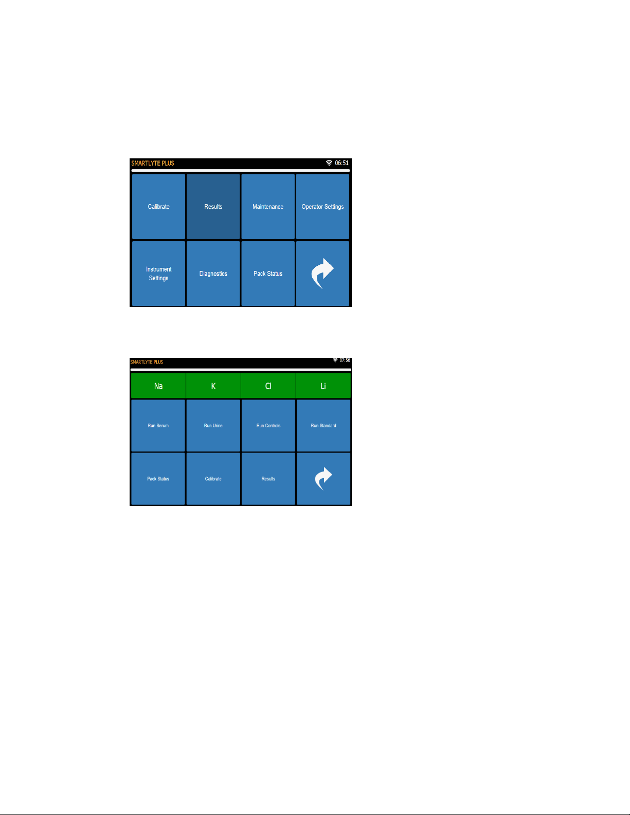
1.2. Software Operation........................................................................................................................... 10
1.3. Description of Modules.................................................................................................................... 11
1.3.1. Mechanical Assemblies............................................................................................................... 11
1.3.1.1. Front Door Assembly ............................................................................................................... 11
1.3.1.2. Rear Panel Subassembly........................................................................................................ 14
1.3.1.3. Power Supply Subassembly ................................................................................................... 15
1.3.1.4. Power Inlet Module Subassembly ......................................................................................... 16
1.3.1.5. CPU Board (CN-A4405) .......................................................................................................... 17
1.3.1.6. Aspiration Assembly................................................................................................................. 21
1.3.1.7. Electrode Tray Assembly ........................................................................................................ 26
1.3.1.8. Peristaltic Pump Rotor (CN-A4014)....................................................................................... 29
1.3.1.9. Peristaltic Pump Motor............................................................................................................. 30
1.3.1.10. Solenoid Valve System ........................................................................................................ 31
1.3.1.11. Printer Assembly (CN-A4060)............................................................................................. 34
1.3.1.12. RFID Board (CN-A4054)...................................................................................................... 36
1.3.1.13. Valve Board (CN-A4018)..................................................................................................... 36
1.3.1.14. Display Board (CN-A4406).................................................................................................. 38
1.3.1.15. Interface PC........................................................................................................................... 39
1.4. Fluidic Modules.................................................................................................................................. 40
1.4.1. Standard A..................................................................................................................................... 40
1.4.2. Standard B and C......................................................................................................................... 40
1.4.3. Reference Solution ...................................................................................................................... 40
1.4.4. Waste Liquids ............................................................................................................................... 40
1.4.5. Fluidic Flow Path .......................................................................................................................... 41
1.4.6. Pinch Valve Tubing Set (AV-BP5193) ...................................................................................... 42
1.4.7. Fluidic Diagram............................................................................................................................. 45
1.5. Electronics .......................................................................................................................................... 46
1.5.1. Block Diagram of SmartLyte® Plus........................................................................................... 46
1.5.2. CPU Board .................................................................................................................................... 46
1.5.3. Power Circuits............................................................................................................................... 48
1.5.4. Microcontroller .............................................................................................................................. 48
1.5.5. EMF and Noise Shielding ........................................................................................................... 48
1.5.6. Fluid Pack Sensor ........................................................................................................................ 48
1.5.7. Valve Drivers................................................................................................................................. 49
1.5.8. Pump Motor Driver....................................................................................................................... 49
1.5.9. Input Amplifiers............................................................................................................................. 49
1.5.10. Temperature Sensor circuit..................................................................................................... 49
1.5.11. Analog Channel and A/D Converter ...................................................................................... 49
1.5.12. CPU board Connector ............................................................................................................. 49
1.5.13. Valve Board ............................................................................................................................... 49
1.5.14. Display Board............................................................................................................................ 50
1.5.15. Printer ......................................................................................................................................... 50
1.5.16. Shielding and Grounding......................................................................................................... 50
1.5.17. Interface PC............................................................................................................................... 50
2. Scheduled Maintenance......................................................................................................................... 51

Table of Contents
ECO 9099 SOP05-5090F Rev.00 Effective Date: 12/20/18 Page 6 of 58
2.1. Daily ...................................................................................................................................................... 51
2.2. Weekly Maintenance......................................................................................................................... 51
2.3. Monthly Maintenance ....................................................................................................................... 51
2.4. Six Month Maintenance ................................................................................................................... 51
2.5. Annual Preventive Maintenance.................................................................................................... 51
3. Troubleshooting ....................................................................................................................................... 52
3.1. Error Messages and Troubleshooting......................................................................................... 52
4. Parts List .................................................................................................................................................... 58
4.1. Consumables...................................................................................................................................... 58
4.2. Analyzer Parts for Repair ................................................................................................................ 58

1 Introduction
ECO 9099 SOP05-5090F Rev.00 Effective Date: 12/20/18 Page 7 of 58
1. Introduction
The Service Manual for the SmartLyte®Plus Electrolyte Analyzer contains the technical information
needed to ensure easy fault identification. This manual is intended to be complementary to the Operator's
Manual where detailed instructions for operation, maintenance and troubleshooting are provided.
As for all clinical instrumentation, a thorough understanding of the principles of operation is prerequisite to
attempting service of this product. Training along with experience will enhance the use of this manual.
Service and repair of the SmartLyte®Plus analyzer should be performed only by qualified repair
technicians. Care should be taken when removing the covers as hazardous voltages are exposed. Use
only accepted electronic check procedures and static protection when replacing and handling all
electronic parts.
This manual is divided into 4 chapters to facilitate location of technical information. Chapter 1 includes all
mechanical, fluidic and electronic assemblies are described. Chapter 2 outlines routine maintenance and
troubleshooting procedures. Chapter 3 includes troubleshooting, including error messages. Finally,
Chapter 4 includes part identification.

1 Introduction
ECO 9099 SOP05-5090F Rev.00 Effective Date: 12/20/18 Page 8 of 58
1.1. General Description
1.1.1. Measurement
SampleTypes: Whole Blood, Serum, Plasma, QC Material, Aqueous
Reported Parameters Range Measurement Resolution
Sodium, Na+40 - 200 mmol/L 0.1 mmol/L
Potassium, K+1.5 -15 mmol/L 0.01 mmol/L
Chloride, Cl-50 - 200 mmol/L 0.1 mmol/L
Calcium, Ca++ 0.3 - 5.0 mmol/L 0.01 mmol/L
Lithium, Li+ 0.2 – 5.5 mmol/L 0.001 mmol/L
Sample Type: Urine
Reported Parameters Range Measurement Resolution
Sodium, Na+1 - 300 mmol/L 1 mmol/L
Potassium, K+5 - 120 mmol/L 0.1 mmol/L
Chloride, Cl-50 - 200 mmol/L 1 mmol/L
Calcium and Lithium are not measured in urine samples.
1.1.2. Operating Configurations
Sample type Whole blood, serum, plasma, urine, QC material, Aqueous samples
Sample device Syringe, sample cup, collection tube
Sample size 95 uL
Analysis time 28 seconds
Sample rate 128 per hour
Sodium (Na+) sensor Ion-selective, flow-through, glass capillary electrode
Potassium (K+) sensor Ion-selective, flow-through, liquid membrane electrode
Chloride (Cl-) sensor Ion-selective, flow-through, liquid membrane electrode
Calcium (Ca++) sensor Ion-selective, flow-through, liquid membrane electrode
Lithium (Li+) sensor Ion-selective, flow-through, liquid membrane electrode
Reference System Open liquid junction calomel electrode
Calibration Fully automatic
1 point with each sample
2 point every 4 hrs (Lithium, 3 point)
Warm-up time 2 minutes
Temperature Room temperature, 15 - 32° C, 60 - 90° F
Humidity Maximum 85% relative humidity, non-condensing

1 Introduction
ECO 9099 SOP05-5090F Rev.00 Effective Date: 12/20/18 Page 9 of 58
Data management Quality Control memory storage, 3 levels, 500+ values each;
Calculation of mean, standard deviation, coefficient of variation (CV)
Samples, 10000+ measurements
Diagnostic Programs Tests selected in Diagnostic Menu
Electronics Microprocessor-controlled and Interface-PC
Display Graphical touch screen, 800 x 400 pixels
Printer Integral thermal printer, 16 character width
Interface RS232C Serial Port
4 USB Ports
LAN/Ethernet
Electrical requirements 100 - 240 V, 50/60 Hz,
1.4 A max.
Self-adjusting
Nominal power
Consumption Minimum 10W/hour
Typical 25W/hour
Maximum 35W/hour
Dimensions
Height 335 mm; 13.2"
Width 315 mm, 12.4"
Depth 295 mm; 12.0"
Weight approx. 6kg; 14 lbs;
Classifications
Safety category I
Device Type B (according to EN 60601-1, 6010-2-101)
Mode of operation Continuous
Protection class IP 20
Explosion protection The device is not designed for operation in explosive environments.
Approvals CSA C22.2, EN 61010-1, CE, FCC Class B
Data subject to change without notice. Technical information is supplied for general informational
purposes only.

1 Introduction
ECO 9099 SOP05-5090F Rev.00 Effective Date: 12/20/18 Page 10 of 58
1.2. Software Operation
Software operation of the SmartLyte®Plus analyzer is accessed through the touch screen buttons. There are two
Main Menus from which all functions can be accessed. Through the Operations Menu, the Diagnostics function
can be access to aid in servicing the instrument.
Operations
Figure 1-1 Main Menu
Measurment
Figure 1-2 Measurement Menu

1 Introduction
ECO 9099 SOP05-5090F Rev.00 Effective Date: 12/20/18 Page 11 of 58
1.3. Description of Modules
1.3.1. Mechanical Assemblies
1.3.1.1. Front Door Assembly
The front door assembly is comprised of the following parts,
1. Front Door
2. Plastic Window
3. EMI Window
4. Door Magnets
Figure 1-3 Front Door Assembly, Front View
Front Door
Assembly
Plastic Window
on Front

1 Introduction
ECO 9099 SOP05-5090F Rev.00 Effective Date: 12/20/18 Page 12 of 58
Figure 1-4 Front Door Assembly, Rear View
To remove the front door from the analyzer;
1. Move the analyzer to the edge of a work surface so the analyzer door, when opened, will
extend beyond and below the work surface.
2. Remove the red ground connector from the Right Angle Tab by grasping the red connector
and pulling to the left exposing the Right Angle Tab. (Figure 1-5)
Figure 1-5 Door Ground Connector, Red
3. Then remove the ground screw, external tooth washer, right angle tab, and hex nut. (Figure
1-6)
Ground Connector
EMI Window
beneath Plastic
Door Magnets
Right Hinge Pin
Copper Conductive
Tape

1 Introduction
ECO 9099 SOP05-5090F Rev.00 Effective Date: 12/20/18 Page 13 of 58
Figure 1-6 Door Hinge Attachment Details
4. With one hand, hold the analyzer door near the right side hinge pin. (Figure 1-7)
5. Ensure the door is not on the work surface.
6. With the other hand, gently apply pressure to the middle rear area of the door. This will flex
the door slightly and allows the right hinge pin to clear the retaining hole in the main chassis.
7. Remove the right hinge pin then the left so the door can then be removed from the analyzer.
(Figure 1-7).
Figure 1-7 Door Details for Removal
The window is comprised of two layers, the EMI window and the plastic window. Both can be
replaced in the field.
1. From the rear side of the door, (Figure 1-4), gently press the window and snapping the EMI
and plastic window out the front side of the door.
2. Verify that the copper conductive tape is still adhered to the both the front and back surface
of the door.
3. Remove adhesive backing from the EMI Window.
4. Place the EMI Window first over the opening on the front side of the door.
5. Press along the frame of the window and ensure good contact of the EMI window with the
copper tape on the frame of the window.
6. After removing the adhesive backing, apply the plastic window over the EMI window pressing
along the frame again to ensure good contact.
Ground Screw
External Tooth
Washer
Right Angle Tab
Hex Nut
Apply Gentle
Pressure
Right Hinge

1 Introduction
ECO 9099 SOP05-5090F Rev.00 Effective Date: 12/20/18 Page 14 of 58
1.3.1.2. Rear Panel Subassembly
The Rear Panel Subassembly contains the Power Supply Subassembly, the Power Inlet Module
and the External Communication Board. To separate the Rear Panel Subassembly, (Figure 1-8)
from the Front Case perform the following steps,
Figure 1-8 Rear Panel with Connectors and Power Supply
1. Ensure power is off.
2. Disconnect RS232 cable if attached.
3. Disengage the 4 screws in the corners of the back case.
4. Move the back case a few inches away from the chassis.
5. Disconnect cables and wires so that the rear case can be separated from the front case.
(Figure 1-8)
Figure 1-9 Connectors and cables on CPU board
Interface PC with 4
USB Ports & LAN
connection
Com Board Ribbon
Cable Connector
Power Supply
Module
Black Power Inlet
Module
Interface PC
Ribbon Cable
Red Instrument
Ground Connector
Power Supply Ground
Connector Tab

1 Introduction
ECO 9099 SOP05-5090F Rev.00 Effective Date: 12/20/18 Page 15 of 58
6. Disconnect the communication ribbon cable from the External Communication Board on the
back panel leading to the Display Board.
7. Disconnect the power supply cable attached to the CPU board by depressing the locking clip
on the left side of the connector and gently pulling the power cable out.
8. On the left side of the chassis, pull the top red grounding wire connector off.
9. Separate the rear panel from the front panel.
1.3.1.3. Power Supply Subassembly
To access the Power Supply Subassembly, the Rear Panel must be removed first.
1. Ensure the power is off.
2. Remove the Rear Panel according to Section 1.3.1.2
3. Disconnect the Power Inlet Module Connector (Figure 1-10)
Figure 1-10 Rear Panel with Power Supply and Main Power Receptacle
4. Remove Ground Cables from Power Inlet Module and left side of Dual Tab.
5. Finally, remove the four screws securing Blue Ring Connector and the Power Supply
Mounting Plate to the Rear Panel. (Figure 1-10 screws circled in red)
6. The Power Supply Subassembly can be removed, (Figure 1-11)
Figure 1-11 Power Supply and Ground Cable Assemblies
Power Supply
Connector to CPU
Board
Power Supply
Connect To
Mounting Plate
Black Power Inlet
Module
Red Ground
Connectors
Power Inlet
Module Connector

1 Introduction
ECO 9099 SOP05-5090F Rev.00 Effective Date: 12/20/18 Page 16 of 58
Figure 1-12 Ground Cable Assemblies
1.3.1.4. Power Inlet Module Subassembly
The Power Inlet Module can be found on the Rear Panel (Figure 1-13), to separate from the Rear
Panel.
1. First follow the instructions in Section 1.3.1.2 to separate the Rear Panel from the Front
Case.
2. Remove Ground Wire from the Power Inlet Module.
Figure 1-13 Rear Panel with Power Inlet Module
3. Turn over the Rear Panel.
4. Remove the two screws on the external face of the Rear Panel. (Figure 1-14)
Power Inlet
Module Connector
Ground Wire
Connector
Power Inlet
Module
Side of Dual Tab
Connect to Power
Inlet Module
Connect to Left
side of Dual Tab
Connect to Right
side of Dual Tab

1 Introduction
ECO 9099 SOP05-5090F Rev.00 Effective Date: 12/20/18 Page 17 of 58
Figure 1-14 Power Inlet Module removal
Figure 1-15 Power Inlet Module
1.3.1.5. CPU Board (CN-A4405)
The CPU board can be replaced when there is a malfunction. ESD precautions should be
exercised to prevent damaging the electronic components. To remove and replace the CPU;
1. First remove the Rear Panel according to instructions in Section 1.3.1.2 to expose the CPU
board.
2. Once the Rear Panel is removed, unplug the Display cable from the CPU board.

1 Introduction
ECO 9099 SOP05-5090F Rev.00 Effective Date: 12/20/18 Page 18 of 58
Figure 1-16 Connectors and cables on CPU Board
3. On the CPU board, unclip the top and bottom tabs of the valve board connector. Holding the
locking tabs open at the same time helps to push the ribbon cable connector out of the CPU
connector.
4. Move the valve ribbon cable to the side.
5. Remove the 6 screws with their plastic washers that hold the CPU board to front case.
(Figure 1-16 circled in red).
6. Carefully pull the CPU board off the alignment pin (Figure 1-16 circled in white). Ensure the
RFID board and the printer is not dislodged.
7. Handle board carefully so as to not damage the Electrode Pins on the front of the CPU
board.
8. Each Pin can be removed by pulling the Electrode Pin from its socket. (Figure 1-19)
Alignment Pin
Display Cable
Valve Board
Connector
Power Cable
Connector
Top Grounding
Screw
CPU Screws, 6
Interface PC
Ribbon Cable

1 Introduction
ECO 9099 SOP05-5090F Rev.00 Effective Date: 12/20/18 Page 19 of 58
Figure 1-17 Front Case Assembly, No CPU Board
9. Lay the board on an ESD mat or packaging.
Figure 1-18 CPU Board, Back
Shield
Display Cable
Connector
Valve Board
Connector
Power Cable
Connector
RS232 Serial
Port

1 Introduction
ECO 9099 SOP05-5090F Rev.00 Effective Date: 12/20/18 Page 20 of 58
Figure 1-19 CPU Board, Front
To install the CPU board, certain steps should be taken to ensure proper placement.
1. Ensure RFID board is installed with its components and antenna facing the Electrode Pins.
2. Pull each Electrode Pin out slightly so that they extend beyond their normal positions. This
will prevent Electrode Pins from being pushed too far into the socket.
3. Place board on alignment pin. (Figure 1-16)
4. Check that Electrode Pins are placed in front case without pushing pins into their sockets.
5. Also verify RFID board is not dislodged.
6. Secure CPU Board to the front case using the screws and plastic washers, previously
removed. Leave screws slightly loose.
7. Check that each Electrode Pin is entirely visible through the Electrode mating holes. (Figure
1-19)
Optical Sensor
RFID Board
Connector
Electrode Pogo
Pin
Printer
Connector
Electrode Pogo
Pin Socket
Table of contents
Other Diamond Measuring Instrument manuals
Popular Measuring Instrument manuals by other brands

FlowLine
FlowLine MicroPoint LI42 Series owner's manual

Biosan
Biosan DEN-1B User instructions

HACH LANGE
HACH LANGE LINK2SC user manual

EUTECH INSTRUMENTS
EUTECH INSTRUMENTS DO 6PLUS DISSOLVED OXYGEN TEMP instruction manual

Bosch
Bosch FAA-420-RI installation guide

Emerson
Emerson Daniel Ultrasonic 100 Series INSTALLATION PROCEDURE

UINICS
UINICS SP-564A Series instruction manual

Endress+Hauser
Endress+Hauser Proline Promag 10D technical information

Power Innovations
Power Innovations EnterprisePlus user manual

Leica
Leica Disto Special5 user manual

MPSC
MPSC HeRO solo manual

Endress+Hauser
Endress+Hauser Levelflex FMP53 operating instructions