INSTALLATION
To install the SX-200/400 or SX-600/1000 simply connect coaxial cable directed to the antenna connector marked "ANT",and
The cable coming from the transmitter or from the linear amplifier to the connector marked "TX"
SX-200/400 or SX-600/1000 is ready to operate.
POWER MEASUREMENTS
I Select the RANGE (3) switch on the end-scale position value as to the power of the unit
2 Select the FUNCTION (4) switch in the power position
3 Select the POWER switch the FWD position to measure the direct power(from the radio to antenna)
or REF position to measure the reflected power(from antenna to the radio)
4 Select the power value can be read on the corresponding scale.
SWR MEASUREMENTS
I Select the RANGE (3) switch on the end-scale position value as to the power of the unit.
2 Select the FUNCTION (4) switch in the CAL position .
3 Let the radio transmit and adjust the instrument by turning the CAL knob, position the end-scale index in the
CAL position.
4 Select the FUNCTION (4) switch in the SWR position
5 Read the SWR value in the above scale.
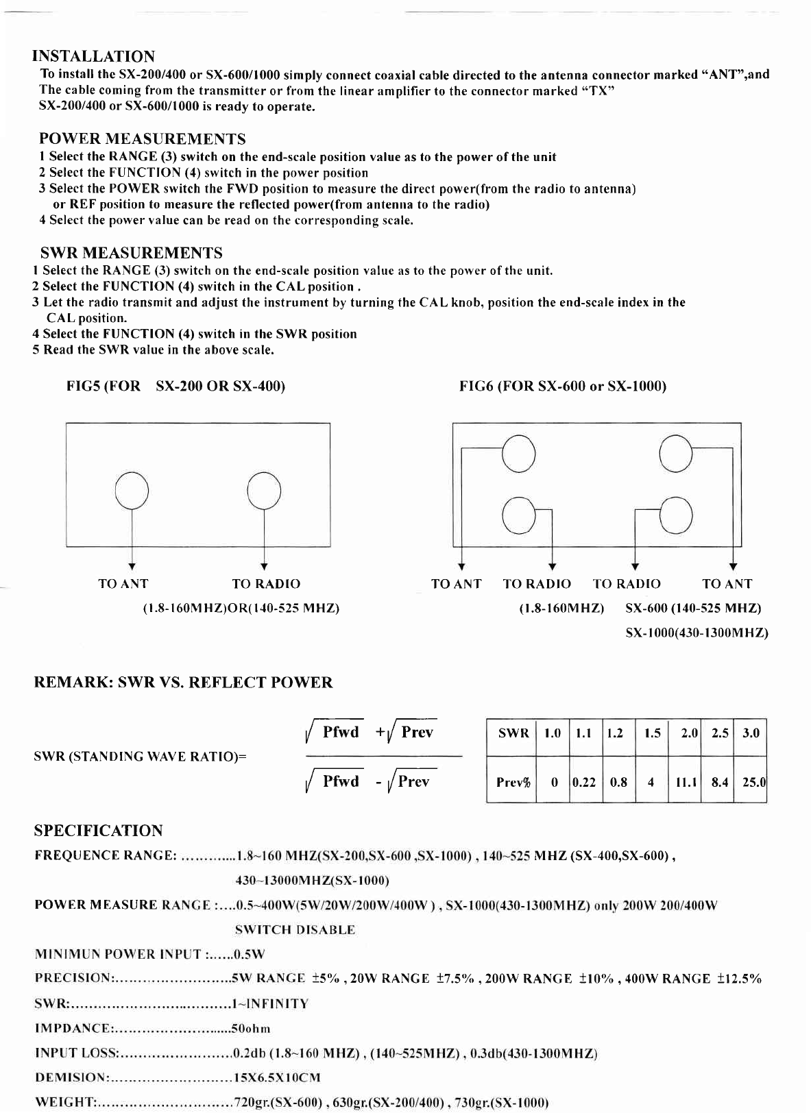
FrGs (FOR SX-200 OR SX-400) FIG6 (FOR SX-600 or SX-1000)
TO ANT TO RADIO TO ANT TO RADIO TO RADIO TO ANT
(f .8-r60MHZ) SX-600 (r40-s25 MHZ\
(r.8-r 60M HZ)OR( | 10-s2s M HZ)
sx-r000(430-1300M HZ)
REMARK: SWR VS. REFLECT POWER
/ rrwo +y' Prev
SWR (STANDING WAVE RATIO): i pr-d tF';
SPECIFICATION
FREQUENCE RANCE: MHZ (SX-400,SX-600),
SWR t.0 l.l 1.2 1.5 2.0 tq 3.0
Prev% 00.22 0.8 4n.l 8.4 25.1
POWER MEASURE
t5% ,2OW RANGE t7.5o/", 200w RANGE +l0o/o ,400W RANGE t12.5'/o


