DiaSys O-Maxi OM Series User manual

O-Maxi operator’s manual Version: 2020.02.10 0
Operator Manual
For
Water purifier

O-Maxi operator’s manual Version: 2020.02.10 1
CONTENT1
Safety Informations ......................................................................................................................... 22
2.1 Warning labels......................................................................................................................... 2
2.2 Safety instructions................................................................................................................... 2
Introduction to the system.............................................................................................................. 33
3.1 Introduction............................................................................................................................. 3
3.2 Overview of the system (front view)....................................................................................... 4
3.3 Overview of the system (back view) ....................................................................................... 5
3.4 Pressure gauges....................................................................................................................... 6
3.5 General description ................................................................................................................. 6
3.6 Description of the control unit ................................................................................................ 7
Controller VERSION 1 ...................................................................................................... 73.6.1
Controller VERSION 2 ...................................................................................................... 83.6.2
3.7 Technical specifications........................................................................................................... 9
Installing the water purifier........................................................................................................... 104
4.1 Installations Conditions ......................................................................................................... 10
4.2 Connections........................................................................................................................... 10
4.3 Connections of Resin bottle and Sampling system to test membrane exit .......................... 11
4.4 Connection of the Pressurized tank ...................................................................................... 11
4.5 Installation of the water purifier membrane ........................................................................ 12
System start up.............................................................................................................................. 135
Maintenance and service .............................................................................................................. 146
6.1 Maintenance calendar........................................................................................................... 14
Calandar for the version 1 ............................................................................................. 146.1.1
Calendar for the version 2 ............................................................................................. 146.1.2
6.2 Troubleshooting .................................................................................................................... 15
Version 1........................................................................................................................ 15
6.2.1
Version 2........................................................................................................................ 166.2.2
6.3 Consumables ......................................................................................................................... 18
OP202+/OP302+/OMAXI FILTER KIT (ref. 950019)........................................................ 186.3.1
OMAXI MEMBRANE KIT (ref. 959070)........................................................................... 196.3.2
OP101+/OP202+/OP302+/OMAXI RESIN KIT (ref. 950243) .......................................... 196.3.3
6.4 Maintenance procedures ...................................................................................................... 20
Flow measurement procedure...................................................................................... 206.4.1
Conductivity measurement procedure ......................................................................... 216.4.2
O-Maxi operator’s manual Version: 2020.02.10 2
Change of SEDIMENT FILTER 5 µm ................................................................................ 23
6.4.3
Change of ACTIVE CARBON BLOCK FILTER .................................................................... 246.4.4
Change of SEDIMENT FILTER 1 µm ................................................................................ 256.4.5
Change of the POST TREATMENT CARTRIDGE: SEDIMENT 1 µm .................................. 266.4.6
Change of the REVERSE OSMOSIS MEMBRANE ............................................................ 276.4.7
Change of FLOW RESTRICTOR ....................................................................................... 286.4.8
Change of the IONS EXCHANGERS RESINS BOTTLE ....................................................... 296.4.9
6.5 Spare parts............................................................................................................................. 30
6.6 Flow path diagram................................................................................................................. 32
Flow path diagram Version 1......................................................................................... 32
6.6.1
Flow path diagram Version 2......................................................................................... 336.6.2
Packing list..................................................................................................................................... 347
SAFETY INFORMATIONS2
Read the safety information before installing the water purifier
2.1 WARNING LABELS
Before reading the manual, please get familiarized with the following icons used in this manual.
Electric Shock
Warnings
2.2 SAFETY INSTRUCTIONS
To ensure the product SECURITY and RELIABILITY, all repairing must be realized with spare parts
available with our after-sales service. If the power cable is damaged, it must be replaced.
Unplug the water purifier power plug. Don’t pull on the wire.
Before all maintenance on the water purifier, turn off the power supply switch and
unplug the power plug.
Use exclusively tap water to supply the water purifier.
- MAXIMUM NETWORK PRESSURE = 6 BARS
- Maximum supply water temperature = 38 °C.
This water purifier needs a main tension 230 volts ~ / 50 Hz.
Don’t connect too much instruments on the same plug in order to not risk fire or
electric shock.
The low voltage electrical installation must comply with local standards.

O-Maxi operator’s manual Version: 2020.02.10 3
INTRODUCTION TO THE SYSTEM3
3.1 INTRODUCTION
The DiaSys water purifier «O-Maxi» is a purified water production system allowing two water
treatment leading-edge technologies:
The BI-REVERSE OSMOSIS, which is currently the most effective and elaborated - membranous
separation process,
The demineralization principle by IONS EXCHANGERS RESINS.
These two associated technologies allow getting water with excellent quality regarding
physical composition, chemical composition (mineral and organic) and micro organic
population.
The "O-Maxi" water purifier exists in 2 versions:
-VERSION 1 (serial number OM - xxx):
-VERSION 2 (serial number OM - 20xxxx) : integrates in addition to version 1 a conductivity
monitor
O-Maxi operator’s manual Version: 2020.02.10 4
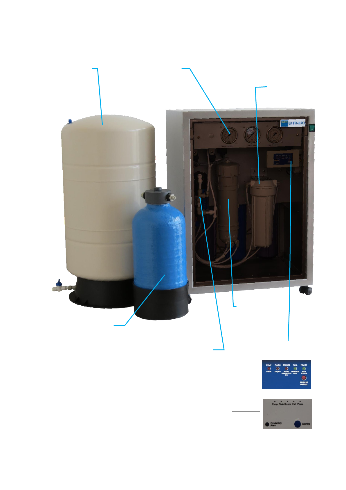
3.2 OVERVIEW OF THE SYSTEM (FRONT VIEW)
Storage
tank
Resin
Bottle
Post
treatment
Reverse
osmosis
membrane
Booster Pump
Pressure
Gauge
Electronic control case
Version 1 :
Version 2 :
O-Maxi operator’s manual Version: 2020.02.10 5
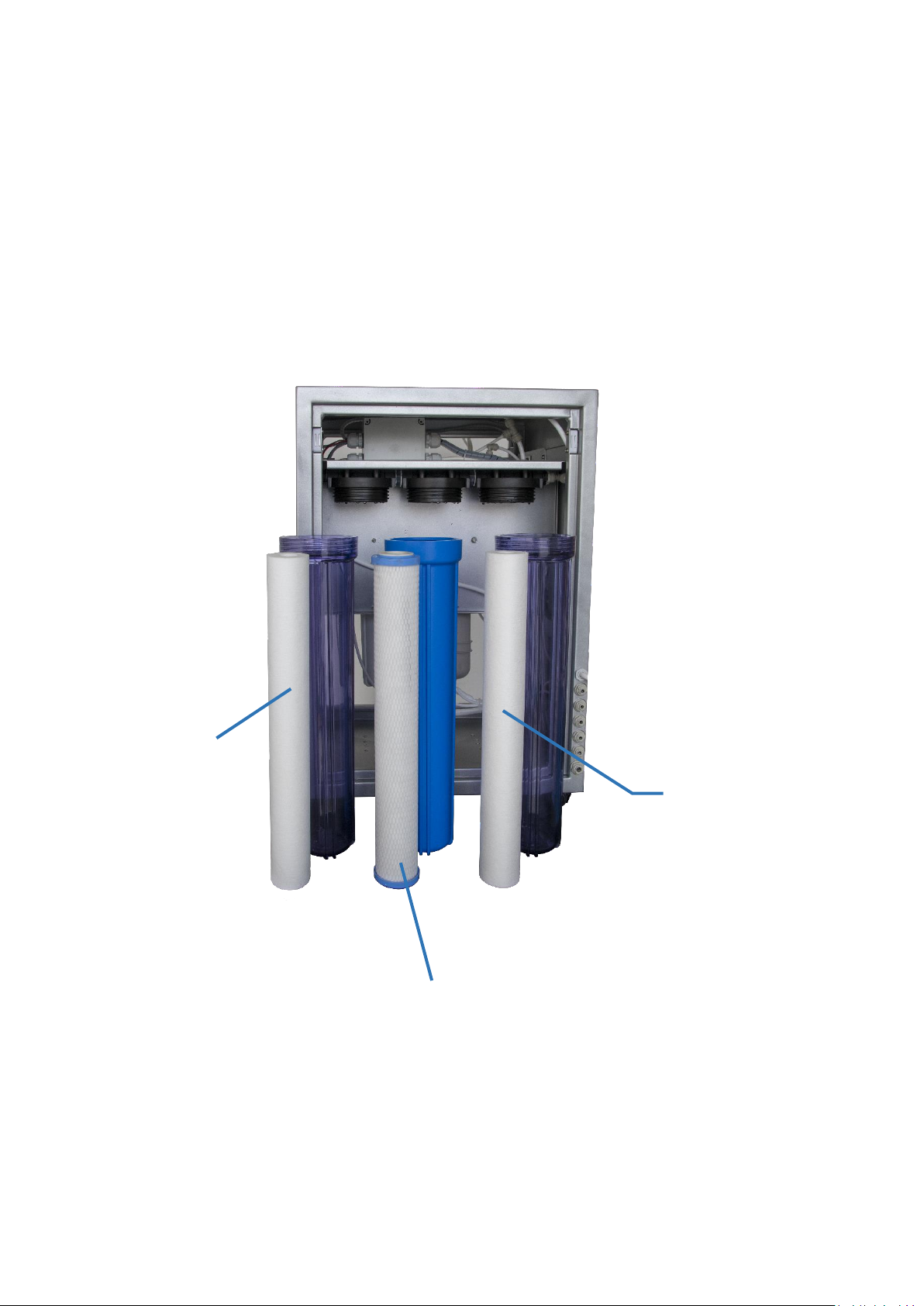
3.3 OVERVIEW OF THE SYSTEM (BACK VIEW)
Filter for
Sediments
5µm
Block active
charcoal fitler
Filter for
Sediments
1µm
O-Maxi operator’s manual Version: 2020.02.10 6
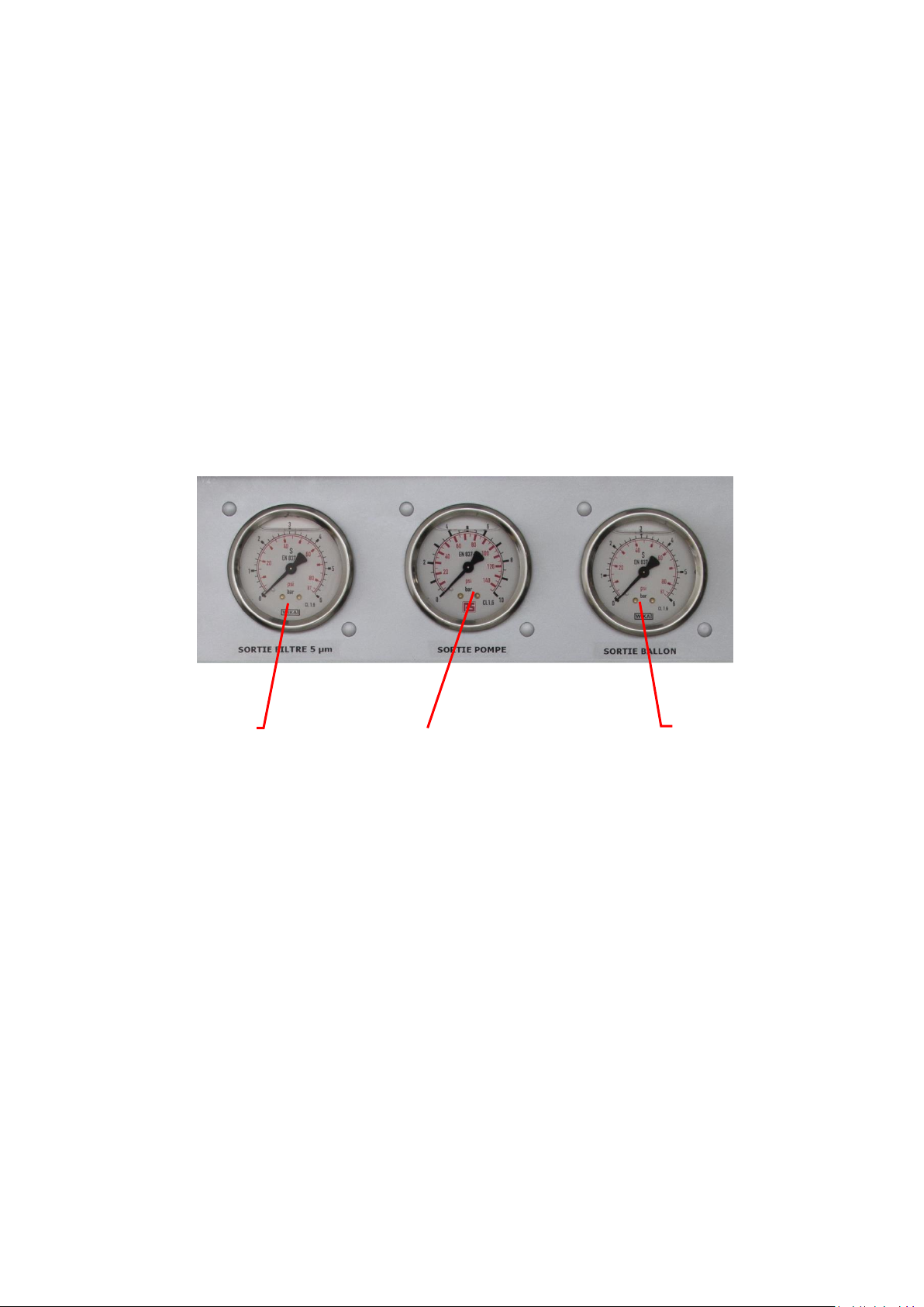
3.4 PRESSURE GAUGES
1/ the pressure gauge « Outlet filters » show the pressure of water supply after filtration. The
guideline value for correct operation is about 3.0 to 4.0 bars (43 to 58 PSI) when the water purifier is
working. If this value is greater than 5 bars (72 PSI), it is imperative to install a pressure reducer on
the water supply network.
2/ the pressure gauges « Exit pump » can check the correct working of pumps and also to the
integrity of reverse osmosis membranes. The guideline value for proper operation is about 4.5 - 8
bars (65 –94 PSI), when the water purifier is working (LED "Power" and "Pump" switch on).
3/ the pressure gauges « exit tank » is used to check storage tank pressure. The max value possible is
about 3 to 3.5 bars (43.5 PSI) when the water purifier is standby (LED « Power » and « Full » switch
on).
3.5 GENERAL DESCRIPTION
The "O-Maxi" water purifier is a water treatment system that includes a series of prefiltration
cartridges for the network water: Sediment filter 5 μm + Block carbon filter + Sediment filter 1 µm
Once this water is treated, it is then injected via a booster pump into 1 reverse osmosis membrane
which is a combination of bi-osmosis process.
The water obtained is thus discharged of 90% of its organic and inorganic compounds.
In order to complete the complete treatment, this water is then injected into an ion exchange resin
bottle and then filtered by a 1 μm post-treatment filter.
The electromechanical assembly is managed by an electronic control unit.
Outlet
filters Pressure
Exit Tank
Pressure
Exit Pump
Pressure
O-Maxi operator’s manual Version: 2020.02.10 7
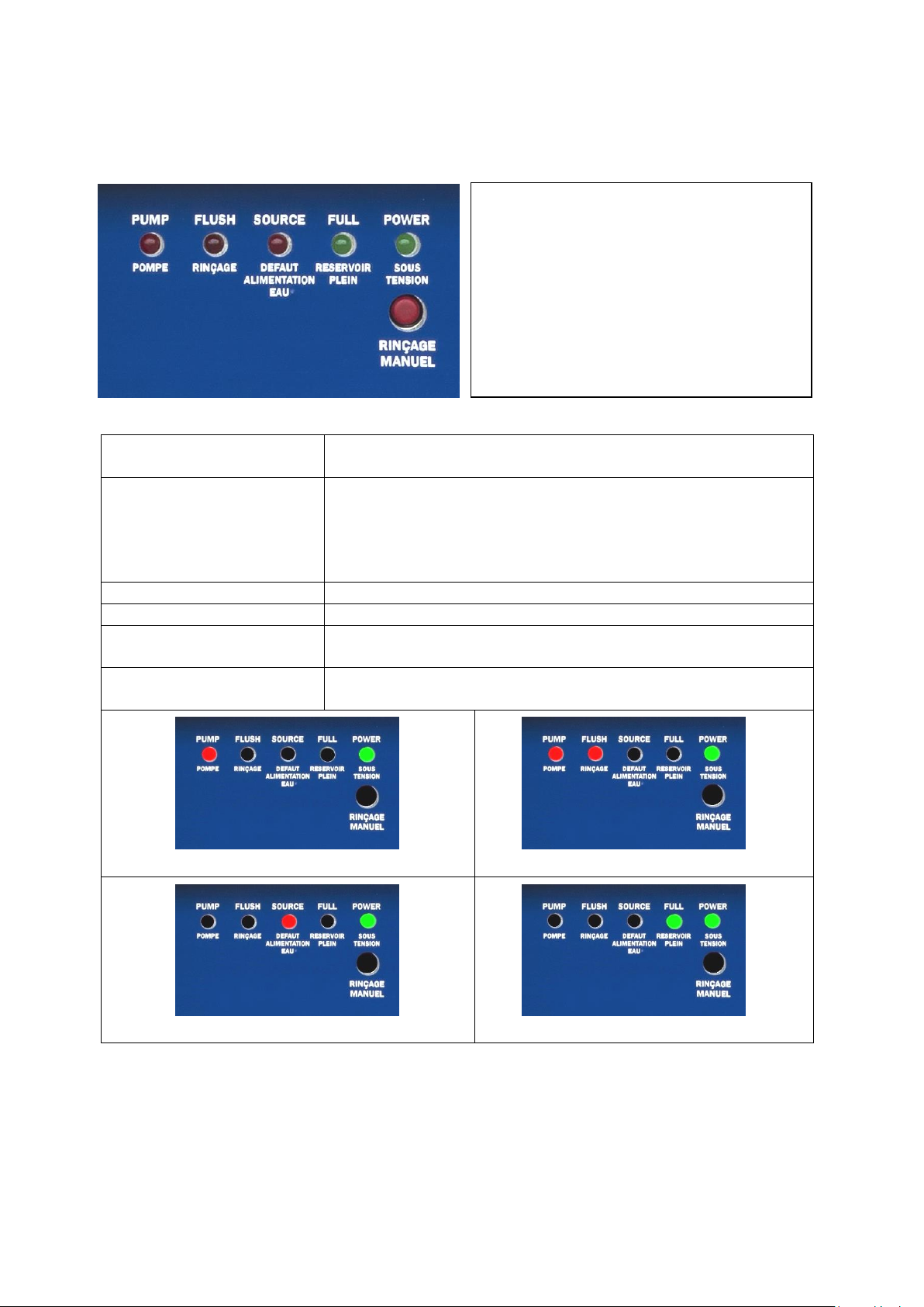
3.6 DESCRIPTION OF THE CONTROL UNIT
Controller VERSION 13.6.1
PUMP indicator turned on
Pump functioning: means the water purifier is either producing or
rinsing.
FLUSH indicator turned on
The water purifier makes an automatic rinsing cycle of the reverse
osmosis membrane; a rinsing (of around 2 min) happens:
- following to the instrument starting,
- following a frequency of around 6 hours,
- following a pressure on the MANUAL button.
SOURCE indicator turned on
Lack of flow or pressure on water supply.
FULL indicator turned on
Full storage tank.
POWER indicator turned on
Water purifier under tension; this indicator is switched on
permanently, whatever the other indicators states are.
MANUAL push button
Press this button makes starting a forced rinsing of the membrane
during 2 min.
water purifier producing
Rinsing cycle
Water supply default
Water storage full
Terms meaning:
PUMP : PUMP
FLUSH : RINSING
SOURCE : WATER SUPPLY
FULL : FULL TANK
POWER : UNDER TENSION
MANUAL : MANUAL RINSING

O-Maxi operator’s manual Version: 2020.02.10 8
Controller VERSION 2
3.6.2
PUMP light ON
Pump working: the water purifier is producing or rinsing.
FLUSH light ON
The water purifier is automatically rinsing the reverse osmosis
membrane. A rinsing (around 1 min 30) happens when :
- the machine is starting up
- every 6 hours
- After pushing the WASHING button.
SOURCE light ON
Lack of flowrate or pressure on the water supply.
FULL light ON
Full storage tank.
POWER light ON
Water purifier switched ON: this light is always ON, whatever the
state of the other lights.
WASHING button
Pushing this button launches a membrane rinsing during around 1
min 30.
CONDUCTIVITY ALARM light
Informs you about the water conductivity.
Water purifier producing
Water purifier rinsing
Lack of water supply
Full storage tank
Produced water conductivity < 1µS/cm
Produced water conductivity 1µS/cm<X<5µS/cm
Signification des termes:
Pump : Pump
Flush : Rinsing
Source : Water supply
Full : Full tank
Power : Under tension
Washing : Manual rincing
Conductivity Alarm : Conductivity alarm

O-Maxi operator’s manual Version: 2020.02.10 9
Produced water conductivity > 5µS/cm
3.7 TECHNICAL SPECIFICATIONS
Power supply voltage 230 volts ~ / 50 Hz.
Production flow at 25 ° C 55 liters / hour
Production flow at 10 ° C 40 liters / hour
Resins type Mixbed ions exchange resins
Resins volume 11 liters
Maximum supply water temperature 38 °C (100°F)
Maximum hardness without protection 40 °f (French degree) of TH
Admissible pH 3 to 11
Mini / maxi supply pressure 2 / 5 bars (29 / 87 PSI)
Dimensions (l × h × w) 55 X 73 X 45 cm
Indicative weight 49 kg
This system is recommended for daily consumption over 50 liters.
O-Maxi operator’s manual Version: 2020.02.10 10
INSTALLING THE WATER PURIFIER4
4.1 INSTALLATIONS CONDITIONS
Water inlet (2 to 5 bars) equipped with a turn hand valve or a male exit tap of 15/21 or 20/27.
Protected electric input (230 V ~, 50 Hz + EARTH). Connect the device in a dry area more than two
meters away.
Water drain with a siphon or the drain clamp supplied with the water purifier.
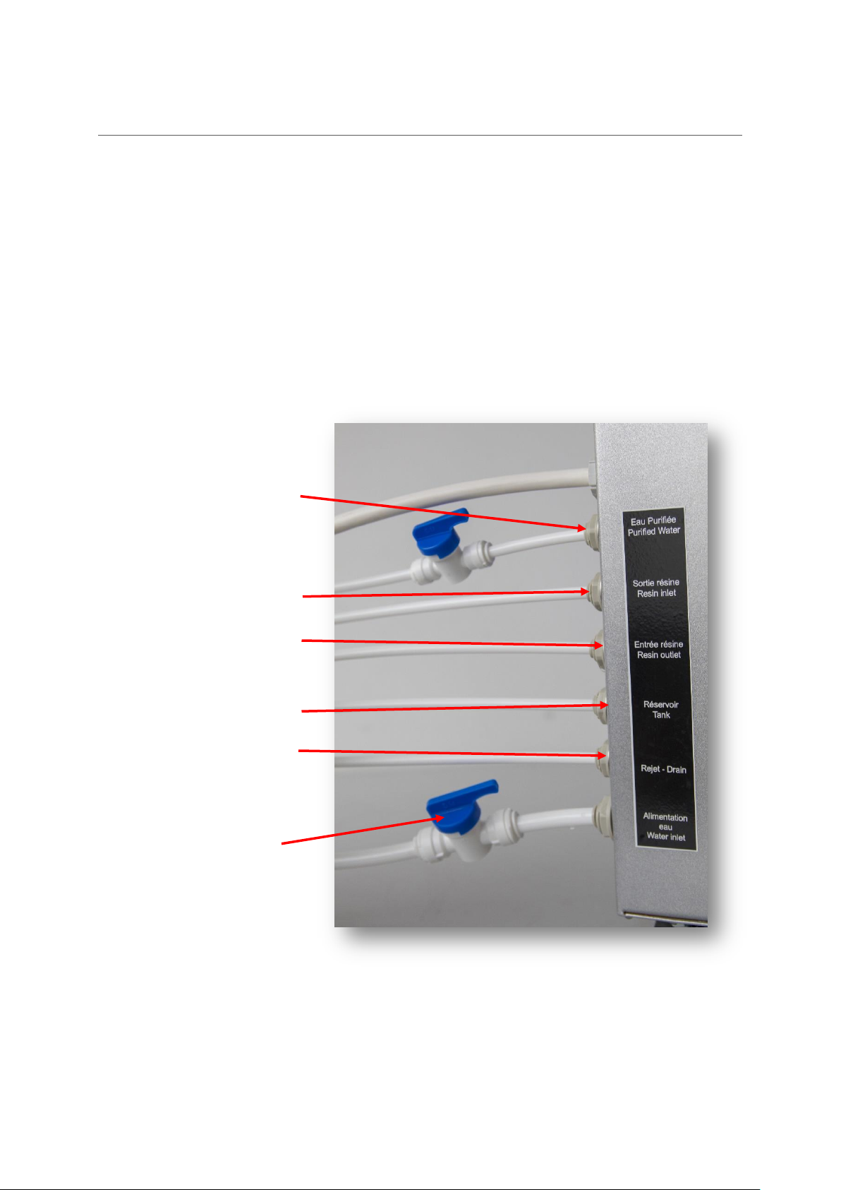
4.2 CONNECTIONS
Connect a hand valve on
the purified water outlet
Connect to the resin bottle
outlet
Connect to the resin bottle
inlet
Connect to the storage tank
Connect to the drain
Must be always OPEN to
not damage the system
Connect a hand valve on
the tap water inlet
O-Maxi operator’s manual Version: 2020.02.10 11
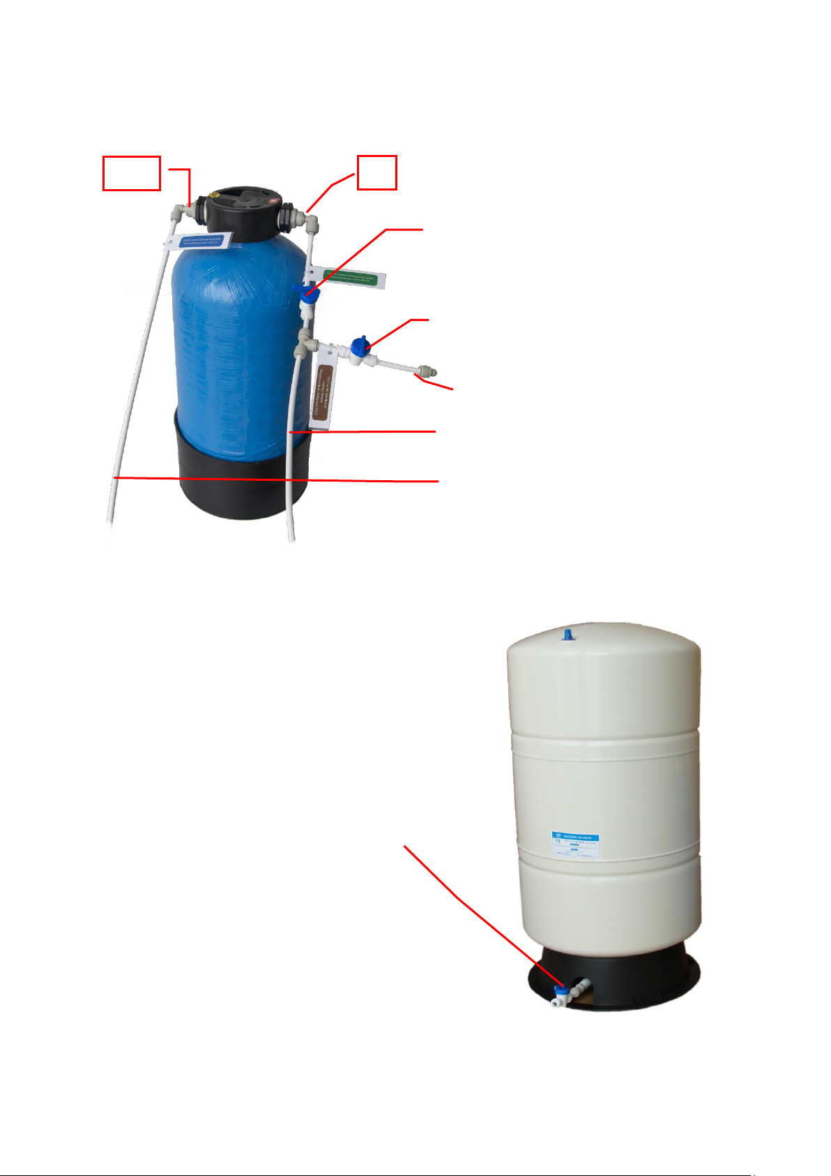
4.3 CONNECTIONS OF RESIN BOTTLE AND SAMPLING SYSTEM TO TEST MEMBRANE EXIT
4.4 CONNECTION OF THE PRESSURIZED TANK
Inlet Resin bottle (to be connected to the
water purifier)
Outlet Resin bottle (to be connected to
the water purifier
Outlet to test membrane conductivity
IN
OUT
Outlet Pressurized Tank (to be connected to the
water purifier)
This valve is open in normal operating mode
This valve is closed in normal operating
mode

O-Maxi operator’s manual Version: 2020.02.10 12
4.5 INSTALLATION OF THE WATER PURIFIER MEMBRANE
1. Disconnect the water inlet pipe from the membrane holder (Figure 1)
2. Remove the membrane holder out of its two plastic clips (Figure 2)
3. Unscrew (by turning to the right) the cap of the membrane holder using the two special keys
provided with the accessories.
4. Once the membrane cap is removed, insert the new membrane (Figure 3), peripheral seal at
the top, to the complete stop: the end of the collecting tube must be flush with that of the
membrane holder. (Figure 4)
figure 1
figure 2
figure 3
figure 4
5. Check that the O-ring is well-positioned at the bottom of the retaining wall of the membrane
holder (see the plan).
6. Unscrew (by turning to the right) the high streaked part ("big cap") of the membrane holder.
7. Joint the membrane on its stirrups.

O-Maxi operator’s manual Version: 2020.02.10 13
SYSTEM START UP5
1. Connect the water purifier hydraulically then electrically.
2. Check all hydraulic connections.
3. Close the storage tank valve.
4. Open the water purifier exit hand valve.
5. Open the tap water supply valve.
6. Electrically switch on the water purifier.
7. The control unit goes through the following phases:
8. Wait (a few minutes) for purified water to drain from the water purifier exit hand valve, then
let about 20 liters flow.
9. Then carry out a conductivity test (see paragraph 6.4.2.2). The value obtained must be 0 to
0.1 μS / cm. Then close the water purifier exit hand valve.
10. Open the storage tank valve and wait for its full refill: "Full" indicator lit in green
11. The control unit goes through the following phase:
12. The water purifier is then operational
The power indicator indicates that the
osmosis unit is energized.
The pump indicator indicates that the pump is
running.
The flush indicator indicates that the system is
in the rinse phase of membrane.
When the flush light goes off the system
enters its production phase.
Version1
Version2
Version1
Version2
Version1
Version2

O-Maxi operator’s manual Version: 2020.02.10 14
MAINTENANCE AND SERVICE6
6.1 MAINTENANCE CALENDAR
In order to insure an optimal functioning of the water purifier, it is necessary to realize a certain
number of controls and maintenance of first level.
These actions must be realized by the customer. The following board gives the controls to make and
the actions of maintenance to realize, their frequency and the operator.
Calandar for the version 16.1.1
Frequency
Operation
DAILY
Check before using purified water that the
indicator « full » is switched on
WEEKLY
Check purified water conductivity
EVERY 3 MONTHES
Check the reverse osmosis membrane exit
conductivity
AT LEAST EVERY 6 MONTHES
depending of conductivity values
Replace the resin bottle. See paragraph 6.4.9
AT LEAST EVERY 6 MONTHES
depending of conductivity values
Replace the pretreatment filters and post-
treatment filter. See paragraph 6.4.3 , 6.4.4 , 6.4.5
, 6.4.6
OCCASIONALLY
Replace the reverse osmosis membrane and
the flow restrictor. See paragraph 6.4.7, 6.4.8
Calendar for the version 26.1.2
Frequency
Operation
DAILY
Check before using purified water that the
indicator « full » is switched on
DAILY
Monitor the conductivity indicator. Refer to
paragraph (6.4.2.2.2) as soon as the conductivity
indicator turns red
EVERY 3 MONTHES
Check the reverse osmosis membrane exit
conductivity. See paragraph 6.4.2.3
AT LEAST EVERY 6 MONTHES
depending of conductivity values
Replace the pre-treatment filters and post-
treatment filter. See paragraph 6.4.3 , 6.4.4 , 6.4.5
, 6.4.6
OCCASIONALLY
Replace the reverse osmosis membrane and
the flow restrictor. See paragraph 6.4.7 , 6.4.8

O-Maxi operator’s manual Version: 2020.02.10 15
6.2 TROUBLESHOOTING
Version 16.2.1
PROBLEMS
POTENTIAL CAUSES
SUGGESTED ACTION
Power light OFF
No power supply
Verify the power supply
wires ; switch power ON
Power supply fuse is broken
Check and replace the fuse
Power light ON
No production of purified
water
indicator PUMP is off
indicator SOURCE is ON
The inlet tap water supply is closed
or has insufficient pressure
Improve water supply
Water inlet tubing folded or
obstructed
Check that the inlet pipe is
not damaged.
Power light ON
No production of purified
water
all control light indicators
OFF
A fuse is broken :
- pump fuse
- fuse in the controller box
Check and replace the fuse
Power light ON
No or low purified water
production
indicator PUMP light ON
Pump running
Pre-treatment clogged
Replace the pre-treatment
filters before the RO
membrane
Weak flow of inlet water
Increase the flow of the
inlet water
Reverse osmosis membrane
clogged
Change the membrane
Power light ON
No or low purified water
production
indicator PUMP light ON
Pump always OFF
Pump fuse burned
Replace the pump fuse
Light indicators FULL and
PUMP alternate
Defective high-pressure sensor or
check valve
Change pressure sensor and
check valve
Power light ON
Lack of pressure and low
flow output
Watertank hand valve closed
Turn ON the watertank
hand valve
Requested pure water volume
above the capacity of the water
purifier
Wait the watertank is filled
again
Lack of pressure in the pressurised
watertank
Re-adjust the air-pressure
of the water tank
purified water conductivity too high
Resin saturated
Replace resin cartridge or
bottle
POWER light ON
FULL indicator ON
Pump OFF
Drain flowing continuously
Inlet solenoid valve defective
Replace the inlet solenoid
valve
Conductivity meter display OFF
Batteries out of order
Replace the batteries

O-Maxi operator’s manual Version: 2020.02.10 16
Version 2
6.2.2
-FLUSH+SOURCE lights: blinking
red
-CONDUCTIVITY ALARM light:
blinking blue
-Flush valve not connected (faulty
contact)
-Check the Flush valve
-PUMP light: blinking green
-FLUSH+SOURCE lights: blinking
red
-CONDUCTIVITY ALARM light:
blinking blue
-3-way valve not connected
-Check the 3-way valve
-PROBLEMS
-POSSIBLE CAUSES
-SUGGESTED ACTION
-POWER light switched OFF
-No power supply
-Plug the system to power
supply
-Power fuse defectuous
-Electric overload (pump,
valves or power supply in
short circuit).
-POWER light switched ON
-No purified water produced
-PUMP light switched OFF
-SOURCE light switched ON
-The tap water valve is closed or
the tar water doesn’t have
enough pressure
-Check the water inlet
-The inlet water pipe is bent or
plugged
-Check the water inlet pipe.
-POWER light switched ON
-Low purified water production
-PUMP light switded ON
-Pump working
-The pre-treatment cartridge is
plugged
-Replace the pre- and post-
treatment filters
-Low water inlet flowrate
-Increase the water inlet
flowrate
-The reverse osmosis membrane
is plugged
-Replace the membrane
-POWER light switched ON
-Lack of pressure and low flowrate
-Storage tank valve closed
-Open the storage tank valve.
-Volume of water required higher
than the system capacity
-Wait for the storage tank to
be full again
-Lack of air pressure in the
storage tank
-Adjust the air pressure of the
storage tank to 0,7 Bar
-Conductimeter display always
switched OFF
-Low battery
-Replace the battery
-PUMP light: blinking green
-FLUSH light: blinking red
-CONDUCTIVITY ALARM light:
blinking blue
-Pump or inlet valve not
connected (faulty contact)
-Check the pump and the inlet
valve

O-Maxi operator’s manual Version: 2020.02.10 17
-PUMP light: blinking green
-SOURCE light: blinking red
-CONDUCTIVITY ALARM light:
blinking blue
-Pressure sensor out of order
-Replace the pressure sensor
-CONDUCTIVITY ALARM light:
blue
-Conductimeter or temperature
sensor out of order
-Replace the sensor
-CONDUCTIVITY ALARM light:
blue/yellow alternating
-Inverted connections between
the conductimeter and
temperature sensor
-Open the control unit and
invert the connections

O-Maxi operator’s manual Version: 2020.02.10 18
6.3 CONSUMABLES
OP202+/OP302+/OMAXI FILTER KIT (ref. 950019)6.3.1
The kit contains the following consumables:
Pre-treatment
The 5 µm sediments cartridge (20")
The active carbon block cartridge ( 20")
The 1 µm sediments cartridge (20")
Post-treatment
The 1 micron post traitement cartridge (10")
The 3 pre-treatment filters must be replaced when a plugging, significant drop of the purified water
production flow and/or sediments 5 µm filter seems dirty.
Note: the 3 pre-treatment cartridges average life time is from 2 to 6 months following the tap water
quality (Material Suspended rate measurable by the turbidity) and the water purifier running time.
The post treatment cartridge must be replaced at the same time than the pre-treatment cartridges.
Filter for sediments 1 µm
Filter for sediments 5 µm
Active carbon block filter
Post treatment filter

O-Maxi operator’s manual Version: 2020.02.10 19
OMAXI MEMBRANE KIT (ref. 959070)
6.3.2
The kit contains the following consumables: 1 Membrane 300 GPD + 1 flow restrictor 300 CC
The reverse osmosis membrane and the flow restrictor must be replaced when the flow of purified
water outlet is significantly low despite of a recent replacement of pre-treatment filters or/and an
important increase in the frequency of the ions exchangers resins bottle replacement.
Note: the average life time of a reverse osmosis membrane is from 1 to 3 years following the tap
water quality, the water purifier running time and the preventive maintenance respect.
OP101+/OP202+/OP302+/OMAXI RESIN KIT (ref. 950243)6.3.3
The resin bottle must be changed when the purified water
conductivity increases.
Note: the average life time of a resin cartridge is from 2 to 6
months following the mineralization (hardness = limestone
rate) of the tap water and the water purifier running time.
Reverse osmosis
membrane 300gpd
Flow Restrictor
This manual suits for next models
1
Table of contents
Other DiaSys Water Filtration System manuals


Popular Water Filtration System manuals by other brands


fish mate
fish mate 2000P-UV quick guide

Advante
Advante H2O Alkaline+ owner's manual

Purifiner
Purifiner Aerobica PDAF-1 054 Owner's operation and maintenance manual

Millipore
Millipore Milli-Q Plus Installation and operation guide

CircuPool
CircuPool SJ20A Installation and operation guide

Kenmore
Kenmore 625.348240 manual