Purifiner Aerobica PDAF-1 054 Installation guide

Aerobica
Chemical Free Iron Sulphur Filtration System
Owner's Operation an Maintenance Manual
PDAF-1 054
Water Quality Control Systems Limite , 605 Denison Street, Markham, Ontario
Tel: 905-944-9465, 888-830-5776, Web: purifiner.com, Email: service@purifiner.com


ENVIRONMENTAL REQUIREMENTS
Location: The water filter and control cannot be exposed to outdoor elements, such as direct sunlight
or atmospheric precipitation. The system may be installed in a covered, open-air structure such as a
carport, residential or commercial building. Weather covers are also available through the Order
Department ( part number 72370 or 71345).
PRE-INSTALLATION INSTRUCTIONS
• Do not install this system where water is microbiologically unsafe or of unknown quality without
adequate disinfection before or after the system.
• This system must be installed in an area that is not affected by extreme heat, cold or the elements.
The selected installation area must be adequate for easy service of all parts.
• This system must be installed in accordance with all applicable state and local laws and regulations.
• This system is designed to treat cold water only and can be installed on any cold water supply.
MAINTENANCE REQUIREMENTS
• Clean the backwash flow control.
• Verify that the flow meter is functioning correctly. Clean the impeller, if necessary.
• Verify the programming of the control. Reprogram, if necessary.
• Verify the minimum and maximum water pressure. Install a pressure reducer, if necessary.
• Replace the filter media every three to five years. Systems used for treatment of high iron will require
replacement of the filter media more often. Call your local dealer to replace the filter media ( part #
14816)
INSTALLATION INSTRUCTIONS
1. SAFETY PRECAUTIONS
• To prevent accident or injury, do not hoist the unit over your shoulder. Use a hand truck to transport
the unit. Note: Do not lay the unit on its side during transportation and/or installation.
• Wear safety glasses and work gloves during installation and service.
2. TEST THE RAW WATER
• Test the raw water supply to ensure it meets the “Application Limitation” on page 3.
3. CHECK WATER PRESSURE
• Use a pressure gauge to confirm that the water pressure does not exceed 120 psi. If the water
pressure does exceed this limit, install a pressure regulator on the inlet pipe of the unit. The minimum
pressure for a filter is 20 psi. 60 psi is the optimum operating pressure.
4. CHECK THE WELL PUMP FLOW RATE
• Proper backwash is required to maintain the life of the filter media. If installed on a well, check to
make sure the well pump can provide a drain flow rate of 5 gallons per minute.
4
System Information continued from page 3.


• Connect the treated water pipe to the OUTLET pipe connection of the bypass valve. When looking at
the front of the unit, the outlet is the pipe connection on the RIGHT side of the valve.
10. TURN ON THE WATER AND TEST FOR LEAKS AND FLUSH THE PLUMBING
• Before turning the water back on, place the system in the bypass position, then close all of the faucets
except one cold water tap from a bath tub.
• Turn the water on slowly and allow the water to flow out the bath tub for several minutes to remove
any dirt, solder, glue, etc. from the plumbing system.
• Once the water runs clear, turn the bypass valve handles to the service position and allow the water
to fill the system. It is common for the first few gallons of water to show some color ( orange to brown)
for a few minutes. Once the water runs clear shut off the bath tub.
• The system will now pressurize, allowing you to check for any leaks.
11. FLUSH THE REMAINING DEBRIS FROM THE SYSTEM
• To flush the remaining untreated water from the plumbing, turn on all the faucets in the house and
flush the toilets (approximately two to three minutes per faucet.)
• Run hot water in the bathtub to remove any remaining untreated water.
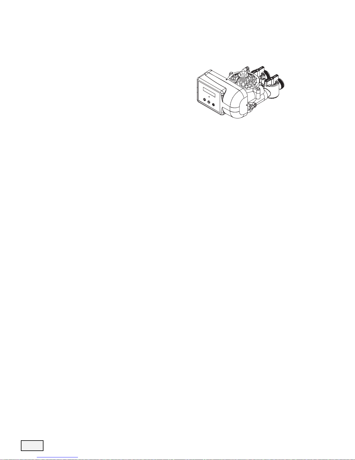
11. INSTALL THE DRAIN LINE AND AIR GAP
• Using the supplied drain line fitting use Teflon tape on the threads and attach to the top of the valve.
Run 1/2 inch ID flexible drain line tubing (not supplied) to an appropriate drain. Most local codes
require an air gap. See pictures on the next page. The Air-Gap is not provided with the product.
Note: Drain line may be plumbed with rigid pipe or PEX, if required by local code. The drain
connection on the valve will accommodate any standard 3/4 inch NPT fitting.
Note: The regeneration cycle is a simple backwash to refresh the filter bed, followed by an intake
of air to establish an air head in the tank. Since no regeneration chemicals are added, the
discharge water may be drained to the outside and used for irrigation in climates where freezing
is not a concern. Please note that iron in the drain water may cause staining, so avoid situations
where the water may splash onto walls, vehicles, patios, etc.
6
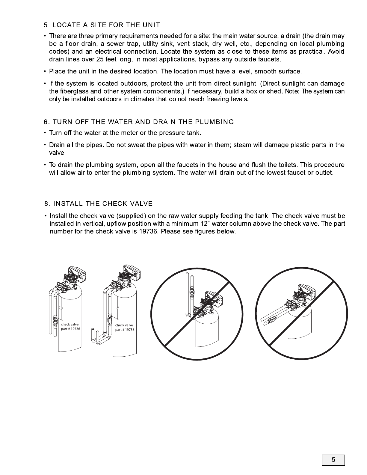
9. CONNECT THE PLUMBING TO THE BYPASS VALVE
• Do not point the soldering torch directly at the system. The thermoplastic material will last a lifetime,
within normal operating temperatures, but will melt in a torch flame.
• To prevent hot water from backing up into the condi
tioner, avoid short connections of pipe between the
conditioner and the hot water heater. If you can’t avoid
a short connection, move the equipment to another
location. As a last resort, install a check valve. If the
check valve causes “water hammer”, install a water
hammer suppressor.
• Connect the raw water pipe to the INLET pipe connection of the bypass valve. When looking at the
front of the unit, the inlet is the pipe connection on the LEFT side of the valve.
INLET
OUTLET


Special Attention for situations where a Filter and a Softener are installed
together:
When a whole house filter and a softener are installed side by side, the preferred approach is to run a
separate drain line from each unit all the way to the point of termination. If this is not done, there is
the potential for drain water from the filter to back feed through the softener and overfill the brine
tank, especially when drain lines are run overhead. (Please note that back feed goes only into the
brine tank, not the service line.)
If circumstances require you to tie the drain lines together, please use one of the following methods
to avoid back feed issues:
Option 1: Run the drain lines from both systems to the point of termination, and tee them together
before the air gap. (See figures below)
Option 2: Install a PVC check valve with a light spring on the Softener side to prevent back flow to
the Softener. (See figure below)
8
WATER IN
TREATED
WATER OUT
2 SEPARATE DRAIN LINES
TO APPROVED DRAIN
LOCATION WITH AIR GAP
FILTER
SOFTENER
2 SEPARATE
DRAIN LINES
AIR GAP
APPROVED FLOOR DRAIN
TEE
FILTER
SOFTENER
SPRING CHECK ON DRAIN
LINE AFTER SOFTENER
WATER IN
TREATED
WATER OUT
TO APPROVED DRAIN
LOCATION WITH AIR GAP

9
CONTROL INFORMATION
POWER ON LED
A green LED is ON when power is applied to the control and the microprocessor is operating properly.
SERVICE REQUIRED
If the message “For Service Call” or “Service Required” displays in the window of the control without
showing the time of day, the control valve has encountered a problem, such as failure to reach the
proper position during regeneration. The valve, the motor assembly, and board must be checked to
diagnose and fix this problem.
Note: It is normal for the message ‘For Service Call’ followed by a phone number to scroll across
the second line of the display. The time of day & capacity remaining will appear on line 1 during
normal operation.
TIME CLOCK
The time clock maintains the time of day for an extended period of time in the event of power loss. A
super capacitor provides this function and eliminates the need of a battery. In the event the power is off
past the charge of the capacitor only the time of day is lost. The rest of the programming is stored in
the memory and will not need to be reprogrammed. When the power is restored the clock will restart
at 8 AM and will need to be reset.
REGENERATION
Once an immediate regeneration is requested, a complete regeneration must occur to clear the
request. Once the regeneration starts, it must finish or the computer board will not clear. Manually walk
(scroll) the control through regeneration to clear the computer board. If the regeneration is aborted and
the request is not cleared, another immediate regeneration will occur.
HIGH-SPEED MOTOR OPERATION IN THE REGENERATION MODE
High-speed motor operation is achieved while stepping the control through the regeneration cycle.
Pressing the scroll button a second time, while in regeneration, activates the higher speed.
PROGRAM LEVELS
To enter any of the program levels, the control must display the time of day and gallons of capacity
remaining (Service Mode).
The system have three program levels available:
1. The Installer’s Level: To access the Installer’s Level, you must enter the five key sequence code
located on page 10. Please refer to pages 10 - 12 for programming information.
2. The End User’s Level: The End User’s Level does not require a special code to access. Please refer
to page 14 for programming information.
3. The Diagnostic Level: Please refer to page 15 for information.

10
HOW TO PROGRAM THE INSTALLER’S LEVEL
To begin, verify that the control is in the Service Mode.
• Press the DOWN ARROW and hold it for 5 seconds; the control will display:
• Within 10 seconds, enter the following key sequence:
DOWN ARROW
DOWN ARROW
SCROLL BUTTON
DOWN ARROW
The control is now in the Installer’s Level. Use the SCROLL BUTTON to advance through the different
settings.
The following settings are available in the Installer’s Level:
1. CAPACITY
The control will display:
• Press the UP or DOWN ARROW to change the volume of treated water between regenerations. The
gallons are in increments of 100. The setting range is 100 to 999,999 gallons (maximum limit).
• Determining the proper regeneration frequency is based on the amount of daily water use and the
amount of Iron in the water. There is no exact science here and its best to reply on personal
experience. In most Iron applications, regenerations no more than three days apart is the normal
treatment. When sulfur is present, daily regeneration maybe needed depending on the amount. See
DAYS OVERRIDE on page 11.
Press the SCROLL BUTTON to advance to the next setting.
2. RESERVE CAPACITY
The control will display:
• To adjust the reserve, press the SCROLL BUTTON. Use the UP OR DOWN ARROW to set the reserve
capacity in increments of 10 gallons, up to 70% capacity of the bed.
Time of Day GL Remaining
System Check
POWER
POWER
KEY BUTTONS:
SCROLL BUTTON
UP ARROW
DOWN ARROW
Capacity: 1000 GL
Rsrv: 200 GL Fxd


• Press the UP or DOWN ARROW to change the length of the air fill cycle. The setting range is 8 to 30
minutes.
Note: This cycle controls the amount of air head in the tank. 13 minutes is a good starting point
for installations.
Press the SCROLL BUTTON to advance the next setting.
7. CYCLE 3 - RINSE
The control will display:
• Press the UP or DOWN ARROW to change the length of the fast rinse. The setting range is 0 to 99
minutes (maximum limit). Note: In most applications, this setting will not need adjusting.
Press the SCROLL BUTTON to advance to the next setting.
8. SERVICE PHONE NUMBER
The control will display:
• If you do not want to change the phone number, leave this setting at NO. Press SCROLL to advance
to EXIT.
• To change the number, select YES; Press the UP or DOWN ARROW and then enter the service phone
number. Press SCROLL to advance through the digits. After setting the number, press SCROLL to
exit the installer’s level; the screen will display:
Press the UP or DOWN ARROW to exit the Installer’s Level.
Note: If you need to recheck settings or make a change, pressing SCROLL when “EXIT” is
displayed will take you back to the start of Installer Settings.
IMPORTANT NOTE: TO ACTIVATE THE NEW SETTINGS, YOU MUST EXECUTE A COMPLETE
REGENERATION. IF YOU DO NOT MANUALLY REGENERATE THE SYSTEM, THE SETTINGS WILL
NOT BECOME ACTIVE UNTIL THE UNIT HAS COMPLETED THE NEXT SCHEDULED REGENERA-
TION.
12
Exit
RINSE: 3 min
Change Phone? No
000-000-0000

13
SYSTEM START UP INSTRUCTIONS
1. Turn the main shutoff valve until it is just barely open. The unit will release any air trapped inside the
valve, without agitating the mineral.
2. Verify that the control is in the Service Mode (time of day and gallons remaining).
3. Allow the water to run for a few minutes until clear; close the faucet.
4. Start an immediate regeneration(see page 11). The first step will be backwash. Allow the water to
flow from the drain until all the air has purged from the system.
5. Advance (scroll) the control to AIR FILL. The system will pull air from outside through the air check
valve. Make sure it works through the whole AIR FILL step (we suggest 30 minutes as a good
starting point) to get enough air in the tank.
6. Advance (scroll) the control to RINSE. Allow the water to flow to drain for 1 minute.
7. Use the SCROLL BUTTON to advance the control back to the Service Mode (time of day and gallons
remaining).
8. The installation is now complete.
Note: This system is an aeration type system so it is to be expected that the water will be cloudy
and sometimes milky especially on the hot side. This is normal and by allowing the water to sit
for a few minutes the air will disappear.

14
HOW TO PROGRAM THE END USER’S LEVEL
To begin, verify that the control is in the Service Mode.
Press the SCROLL BUTTON to advance to the next setting.
The following settings are available in the End User’s Level:
1. TIME OF DAY
The control will display:
• Press the UP or DOWN ARROW to program the time of day.
Press the SCROLL BUTTON to advance to the next setting.
2. VACATION MODE
The control will display:
• Press the UP or DOWN ARROW to activate the Vacation Mode.
Note: The unit will not regenerate when the Vacation Mode is on.
• The Vacation Mode will deactivate when a flow rate greater than 1.5 gallons per minute has been
measured by the meter or when any button is pressed on the control. After the Vacation Mode has
been deactivated, the unit will go into an immediate regeneration.
Note: The vacation mode is mainly useful if you have override set to something other than “OFF”
and do not want the unit to regenerate during an extended absence.
Press the SCROLL BUTTON to advance to the next setting.
3. IMMEDIATE REGENERATION MODE
The control will display:
• If the control is left in this position, the timer will countdown from 10 to 0, initiating a regeneration at
0.
• To avoid an immediate regeneration, press the SCROLL BUTTON before the timer reaches 0.
Press the SCROLL BUTTON to advance to the next setting.
4. DELAYED REGENERATION MODE
The control will display:
• If the control is left in this position, the unit will regenerate at the programmed time. The display will
remain in the Delayed Regeneration Mode until the regeneration has begun.
• To cancel the Delayed Regeneration Mode, press the SCROLL BUTTON.
Press the SCROLL BUTTON to return to the Service Mode.
Time of Day GL Remaining
Set Time of Day
Vacation: OFF
Regen in 10 sec
Regen @ (current setting)


VALVE PARTS LIST
ITEM QTY PART NUMBER DESCRIPTION
1 1 70793 3/4 NPTF TO 1/2 ID HOSE MALE ELBOW (OPTIONAL)
2 1 75074 BACKWASH FLOW CONTROL 5.0 GPM
3 6 72678 SCREW 1/4-20 X 1-1/4 LG HEX WASHER HD
4 1 71083 VALVE BODY COVER
5 1 70658 VALVE COVER O-RING
6 1 72327 TEFLON WASHER
7 1 70665 TEFLON O-RING
8 1 71089 GEAR
9 1 71087 CAM SHAFT
10 1 70656 ROTOR PLATE O-RING
11 1 71132 ROTOR PLATE, COATED
12 1 71084 SEAL DISC, COATED
13 1 71182 INSERT PLATE
14 1 71183 GASKET
15 1 71006 FLOAT VALVE SPRING
16 1 71127 FLOAT VALVE
17 1 70660 FLOAT VALVE O-RING
18 1 72679 VALVE BODY ROTARY BLACK W/INSERTS
19 1 71067 GREEN INJECTOR # 5
20 1 70655 INJECTOR O-RING, LOWER
21 1 70664 INJECTOR O-RING, UPPER
23 1 71947 SPRING CLIP
24 1 71344 RISER INSERT GASKET
25 1 71118 RISER INSERT
26 1 70662 RISER INSERT O-RING
27 1 70663 TANK O-RING
28 1 71010 UPPER BASKET ADAPTER RING
29 2 70630 SCREW #6-19 X 3/4 LG SS
30 1 71060 WORM DRIVE SHAFT
31 1 70616 WORM DRIVE SHAFT TEFLON WASHER
32 2 70666 WORM DRIVE SHAFT O-RING
33 1 70661 PACKING GLAND O-RING
34 1 71069 PACKING GLAND NUT, 15/16-12 THREAD
35 1 70667 O-RING
36 1 70659 O-RING
37 1 70932 UMBRELLA CHECK (OPTIONAL)
38 1 71958 BRINE LINE PLUG
39 170871 BRINE TEE CHECK BALL 3/8 “
40 1 72458 FLOW METER DIFFUSER
41 1 72544 IMPELLER ASSY L W/BUSHING
42 1 72545 HUB FLOWMETER ASSY
43 1 72519 FLOW METER SENSOR CABLE
44 1 19856 IRON FILTER AIR IN-TAKE SCREEN
45 1 19734 CHECK VALVE 3/8 SINGLE
46 1 18772 3/8 HARD PVC TUBING
47 1 70797 COMPRESSION NUT
48 1 71129 TEE/CHECK VALVE
49 1 38812 BLIND NUT
50* 119736 CHECK VALVE 1 IN
* ITEM 50 IS NOT SHOWN IN THE VALVE EXPLODED VIEW ON PAGE 15. PLEASE SEE PAGE 5 FOR DETAILS.
17


19
CONTROL PARTS LIST
ITEM QUANTITY PART NUMBER DESCRIPTION
1 1 38323 FRONT COVER ASSY 2 LINE DISPLAY
2 1 38814 BOARD ASSY PLUMBERS AERATION FILTER
3 2 70618 SCREW #4-24 X 3/8 LG SELF-THREADING
4 1 72519 FLOW METER SENSOR CABLE NGC
5 1 72134 HEYCO BUSHING, SR 5P-4
6 1 70971 POWER LEAD
7 1 70312 HEYCO BUSHING, SR 2P-4
8 1 70962 ELECTRONIC CONTROL BACKPLATE
9 3 71502 SCREW #8-18 X 3/8 LG, SELF-THREADING
10 4 71497 SCREW #10-16 X 1 LG, TYPE BT SS, SELF-THREADING
11 1 70720 DRIVE SHAFT
12 1 71656 MOTOR, 24VCD WITH INTERNAL CAPACITORS
13 1 72261 DRIVE MOTOR SUBASSY
14 1 70668 RETAINING RING
15 1 72451 MICROSWITCHES SUBASSY 2401
16 2 70622 SCREW #2-28 X 3/4 LG, SELF-THREADING
17 1 71185 BRACKET
18 1 71106 HUB AND GEAR
19 1 70625 SCREW #6-32 X 7/16 LG
20 1 70965 CAM SHAFT
21 1 71679 MOTOR LEAD
22 1 72138 TRANSFORMER 120VAC .5 A

20
BYPASS VALVE EXPLODED VIEW AND PARTS LIST
BYPASS VALVE ASSEMBLY PART NUMBER 72316
ITEM QUANTITY PART NUMBER DESCRIPTION
1 2 72599 SCREW 6X32X1/2 TYPE
2 1 72580 BYPASS END CAP 541
3 1 13328 017 O-RING 8730
4 2 72584 RETAINING RING VS-15
5 2 71161 568-363 NUT, BYPASS VALVE
6 2 71162 568-364 RING, NUT RETAINER
7 2 71110 568-320 GASKET
8 1 72669 BYPASS BODY ROTARY
9 2 72585 O-RING 220 DURO
10 2 72586 O-RING 222 DURO
11 2 72583 SEAL BYPASS VALVE
12 2 72670 BYPASS HANDLE ROTARY
Table of contents
Popular Water Filtration System manuals by other brands

Sicce
Sicce SHARK ADV instructions

Evolution Aqua
Evolution Aqua eazypod Installation & operating instructions

Crystal Water
Crystal Water CW-A1004 installation guide

Davis & Shirtliff
Davis & Shirtliff Dayliff Installation & operating manual

PureFlow AirDog
PureFlow AirDog FP-100-4G installation instructions

Corsa
Corsa OSMOTIC ZERO instruction manual