DiaSys mini+ User manual

Operator’s manual version: 2021.06 0
Operator Manual
For the
Water purifier

Operator’s manual version: 2021.06 1
CONTENT
Safety information....................................................................................................................................... 3
2.1 Warning labels..................................................................................................................................... 3
2.2 Safety instructions............................................................................................................................... 3
Introduction to the system.......................................................................................................................... 4
3.1 Introduction......................................................................................................................................... 4
3.2 Technical specifications....................................................................................................................... 4
3.3 Overview of the system (front view)................................................................................................... 5
3.4 Overview of the system (back view) ................................................................................................... 6
3.5 General description............................................................................................................................. 6
3.6 Controller description.......................................................................................................................... 7
Main display................................................................................................................................. 7
Menu display ............................................................................................................................... 8
Detailed information display ....................................................................................................... 8
Phases de fonctionnement.......................................................................................................... 9
Settings menu............................................................................................................................ 10
Screen contrast adjustment ...................................................................................................... 10
General comments on the calibration of the conductivity electrodes ..................................... 11
Calibration of the production conductivity electrode............................................................... 15
Calibration of the membrane conductivity electrode............................................................... 16
Telemetry management............................................................................................................ 18
Installing the water purifier....................................................................................................................... 19
4.1 Installations Conditions..................................................................................................................... 19
4.2 Connections....................................................................................................................................... 19
4.3 Installation of the water purifier membrane .................................................................................... 20
water purifier start-up............................................................................................................................... 21
User maintenance ..................................................................................................................................... 22
6.1 Maintenance calendar....................................................................................................................... 22
Calendar..................................................................................................................................... 22
6.2 System errors..................................................................................................................................... 23
6.3 Integrated conductivity electrode error............................................................................................ 23
6.4 Consumables ..................................................................................................................................... 24
Filter kit « O mini+ » (ref. 950039) ............................................................................................ 24
«O mini+» MEMBRANE KIT (ref. 950023).................................................................................. 25
« O classic/O mini+ RESIN KIT » (réf. 959030)........................................................................... 25

Operator’s manual version: 2021.06 2
6.5 Maintenance procedures .................................................................................................................. 26
Flow measurement procedure.................................................................................................. 26
Understanding conductivity values ........................................................................................... 27
Change of SEDIMENT FILTER 5 µm............................................................................................ 29
Change of ACTIVE CARBON BLOCK FILTER ................................................................................ 30
Change of the 2 RESIN CARTRIDGES.......................................................................................... 31
Change of POST TREATMENT CARTRIDGE................................................................................. 33
Change of the REVERSE OSMOSIS MEMBRANE ........................................................................ 34
Change of FLOW RESTRICTOR ................................................................................................... 35
Packing list................................................................................................................................................. 36
SERVICE...................................................................................................................................................... 37
8.1 ‘SERVICE’ menu ................................................................................................................................. 37
Timings change.......................................................................................................................... 38
Firmware update ....................................................................................................................... 39
Demonstration mode ................................................................................................................ 39
Firmware version display........................................................................................................... 39
8.2 Management of the errors reported by the controller..................................................................... 40
Functional errors ....................................................................................................................... 40
Errors with integrated conductivty electrodes.......................................................................... 42
8.3 Other problems ................................................................................................................................. 42
8.4 Spare parts......................................................................................................................................... 43
8.5 Flow path diagram............................................................................................................................. 45

Operator’s manual version: 2021.06 3
SAFETY INFORMATION
Read the safety information before installing the water purifier
2.1 WARNING LABELS
Before reading the manual, please get familiarized with the following icons used in this manual.
Electric Shock
Warnings
Specific Information without security link
2.2 SAFETY INSTRUCTIONS
To ensure the product SECURITY and RELIABILITY, all repairing must be realized with spare parts available
with our after-sales service. If the power cable is damaged, it must be replaced.
Unplug the water purifier power plug. Don’t pull on the wire.
Before all maintenance on the water purifier, turn off the power supply switch and
unplug the power plug.
Use exclusively tap water to supply the water purifier.
- MAXIMUM NETWORK PRESSURE = 6 BAR
- Maximum supply water temperature = 38 °C.
This water purifier needs a main tension 100-240V~ 1.2 A 50/60 Hz
Don’t connect too many devices on the same plug in order to not risk fire or
electrical shock.
The low voltage electrical installation must comply with local standards.

Operator’s manual version: 2021.06 4
INTRODUCTION TO THE SYSTEM
3.1 INTRODUCTION
The water purifier system «O mini+» produces water of Class 2 as defined in ISO 3696 standard, which is
indented to be used by clinical analyzers.
The principle of purification uses two technologies:
-the REVERSE OSMOSIS, which is currently the most effective membranous separation process,
-the demineralization by ion exchange resin.
These two associated technologies allow getting water with excellent quality regarding physical composition,
chemical composition (mineral and organic) and micro-organic population.
3.2 TECHNICAL SPECIFICATIONS
Power supply voltage 100-240V~ 1.2A 50/60 Hz
Production flow at 25 ° C 15 liters / hour
Production flow at 10 ° C 9 liters / hour
Resin type Mixbed ions exchange resins
Resin volume 1 liter (0.75 + 0.25)
Maximum supply water temperature 38 °C (100°F)
Maximum hardness without protection 4 mmol/L CaCO3
Admissible pH 3 to 11
Mini / maxi supply pressure 2 / 6 BAR
Dimensions (l × h × w) 42 X 39 X 43 cm
Indicative weight 13.5 kg
This system is recommended for daily consumption lower than 30 liters.

Operator’s manual version: 2021.06 5
3.3 OVERVIEW OF THE SYSTEM (FRONT VIEW)
Pressurized water tank
Booster pumper
Controller
Reverse osmosis
membrane
inverse
Post treatment
cartridge

Operator’s manual version: 2021.06 6
3.4 OVERVIEW OF THE SYSTEM (BACK VIEW)
3.5 GENERAL DESCRIPTION
The "O mini+" water purifier includes a set of prefiltration cartridges for filtering the inlet water: 5µm sediment
filter + carbon block filter.
After this stage, the water is injected via a booster pump into one reverse osmosis membrane.
After the reverse osmosis membrane, 90% of the organic and inorganic compounds are already removed.
In order to remove most of all remaining minerals, the water goes through 2 successive ion exchange resin
cartridges and then is filtered by a 1 μm post-treatment filter.
The electromechanical assembly is managed by an electronic controller.
5µm sediment
filter
Active carbon
block filter
Resin filter

Operator’s manual version: 2021.06 7
1.0
US/CM
READY
3.6 CONTROLLER DESCRIPTION
Main display
The conductivity of the produced water is displayed continuously on the main screen.
System status
Conductivity of
produced water
Detailed information button
Unity
Menu access (press 2 seconds)
Flush(wash) button

Operator’s manual version: 2021.06 8
SELECT:PRESS SET 2 SEC
SETTINGS
CALIBRATION
TELEMETRY
CONTRAST
SERVICE
Menu display
The settings menu is displayed after pressing 2 seconds with a tool on the SET button.
Detailed information display
From the main menu, when pressing shortly on the ‘+’ button, the values from various sensors are displayed
momentarily.
DETAILS
INLET
MEMBRANE
3.3
2.0
PRESSURE (BAR)
EC (US/CM)
PRODUCTION
MEMBRANE
1.4
20
This screen is displayed for 10 seconds.
Pressure after the
membrane (BAR)
Conductivity of
produced water
(µS/cm)
Conductivity of the
water after the
membrane (µS/cm)
screen’s name
Water inlet pressure
(BAR)
Menu’s title
Different choices
Selection (press 2 seconds)
Moving in the menu
Operator’s manual version: 2021.06 9
Phases de fonctionnement
1.0
US/CM
120
FLUSH
The conductivity of the produced water can be
different from 1.0.
The remaining time to finish the purge process is
displayed (seconds).
The water purifier is rinsing the membrane after start-
up, periodically (by default each 6 hours), or when
pressing shortly on the ‘FLUSH’ button.
1.0
US/CM
59
PURGE
The conductivity of the produced water can be
different from 1.0.
The remaining time to finish the purge process is
displayed (seconds).
The water purifier is rejecting momentarily the water
which has stagnated in the membrane.
1.0
US/CM
PROD
The conductivity of the produced water can be
different from 1.0.
The water purifier is producing water and its pump is
turning.
1.0
US/CM
READY
The conductivity of the produced water can be
different from 1.0.
The water purifier is ready to use.

Operator’s manual version: 2021.06 10
Settings menu
The settings menu is accessible by pressing with a tool on the SET button for 2 seconds.
SELECT:PRESS SET 2 SEC
SETTINGS
CALIBRATION
TELEMETRY
CONTRAST
SERVICE
The available sub-menus are:
•Calibration of the conductivity electrodes
•Telemetry management
•Screen contrast adjustment
•Tools reserved for service technicians
Screen contrast adjustment
The intensity of display is adjustable.
Press shortly on ‘+’ or ‘-‘to adjust. The rendering is immediate.
When adjusted, validate by pressing with a tool 2 seconds on the ‘SET’ button.
SELECT:PRESS SET 2 SEC
SETTINGS
CALIBRATION
TELEMETRY
CONTRAST
SERVICE
INC:+
DEC:-
OK:PRESS SET 2 SEC
CONTRAST ADJUST

Operator’s manual version: 2021.06 11
General comments on the calibration of the conductivity electrodes
The calibration process is not forced by the system. However it is possible to adjust the displayed value on
the controller’s screen if it is different from the value measured with an external calibrated conductivity
meter.
For the calibration of the electrodes, it is necessary to use a precise external
conductivity meter which must be calibrated (in option, conductivity meter reference
950026).
There is no necessity to calibrate after each change of membrane, filter, or resin
cartridge
3.6.7.1 How to use the external calibrated conductivity meter
1. Let flowing the water to test 15 to 30 seconds.
2. Remove the conductivity meter protection cap.
3. Rinse the protection cap and the conductivity meter probe with the water to test.
4. Renew the operation 2 to 3 times.
5. Fill protection cap of the conductivity meter with the water to test then plunge the conductivity
meter: read the measured value.
6. Renew the operation 2 to 3 times; the retained value will be the last measurement one.
7. Switch off the conductivity meter then place the protection cap.
3.6.7.2 Calibration menu access
SELECT:PRESS SET 2 SEC
SETTINGS
CALIBRATION
TELEMETRY
CONTRAST
SERVICE
SELECT:PRESS SET 2 SEC
CALIBRATION
PROD CONDUCTIVITY
MEMBRANE CONDUCTIVITY

Operator’s manual version: 2021.06 12
3.6.7.3 Use of the adjustment screen
The calibration of the integrated conductivity electrodes is processed with the inner water. In parallel, the
conductivity of this water has to be measured with an external conductivity meter which needs to be
previously calibrated.
OK:PRESS SET 2 SEC
xxxxxx POINT x
CONDUCTIVITY
CALIBRATION
1.5
US/CM
...details…..
•Measure the conductivity with the external calibrated conductivity
meter
•Press on ‘+’ or ‘-‘ until displaying the same value on the controller’s
screen
•Save the calibration point by pressing with a tool on the ‘SET’ button
for 2 seconds
The 2 points of calibrations can not be defined at the same time. The second point of calibration can be useful
after a significant increase of the conductivity. The conductivity of the second point must above the
conductivity of the first point.
Operator’s manual version: 2021.06 13
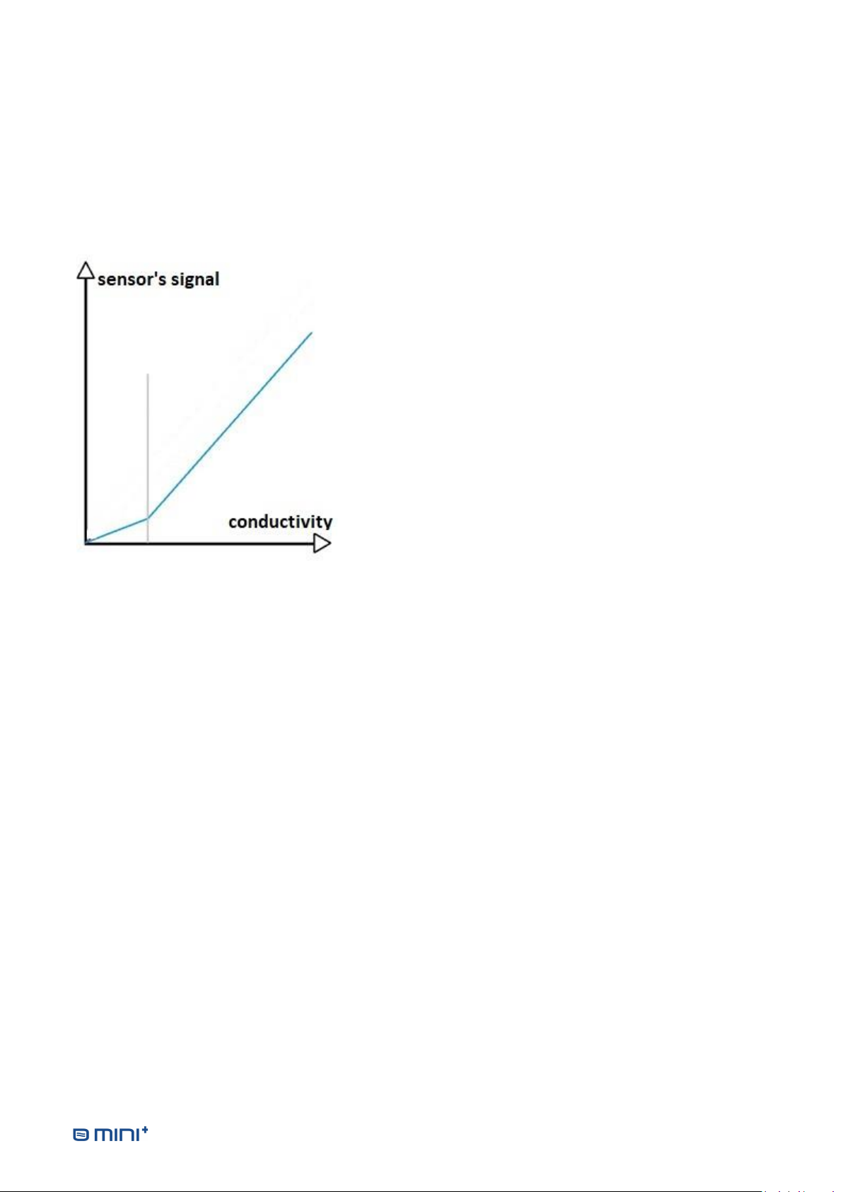
3.6.7.4 Calibration curve with one point
As the electrodes are not accessible by the user, they are able to measure only the conductivity of the water
crossing the system.
The system uses by default its own calibration curve.
It is recommended to calibrate the 1st point of calibration when installing the system, or when replacing filters,
the RO membrane, resin cartridge, électrodes, or the electronics controller (in all these cases, delete the 2nd
point).
•Point of calibration: grey vertical line.
•The calibration curve goes from 0 to the point of calibration.
•Above the point of calibration, the values are adjusted by a
shift from the values measured by the electrode.
Operator’s manual version: 2021.06 14
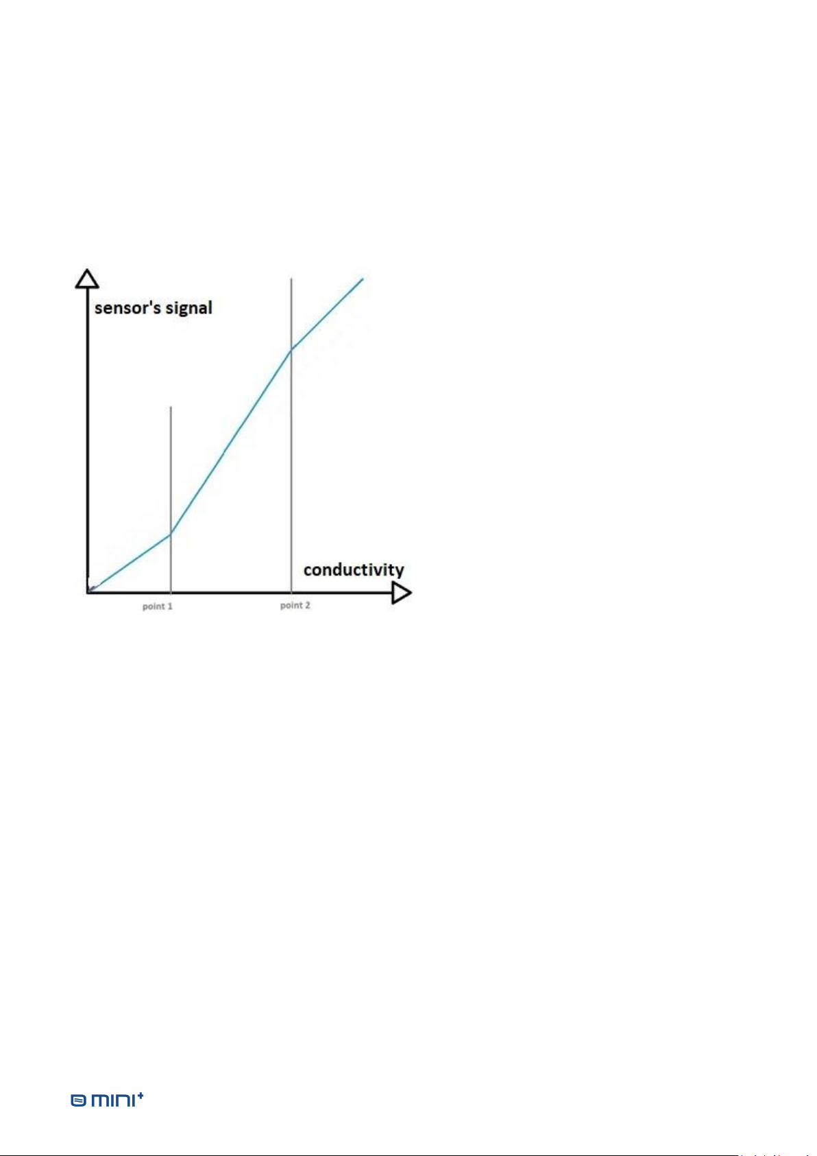
3.6.7.5 Calibration curve with 2 points
As the electrodes are not accessible by the user, they are able to measure only the conductivity of the water
crossing the system.
A 2nd point of calibration can not be used when the conductivity is too close to the conductivity of the 1st point,
without a risk of miscalibration.
It is recommended to choose the 2nd point of calibration with a conductivity close to the maximum.
It is recommended to recalibrate the 2nd point of calibration when filters, the RO membrane or the resin is
close to the saturation.
•Points of calibration: where are the 2 grey
vertical lines.
•The calibration curve goes from 0 to the 1st point
of calibration. The slope is then adjusted.
•The calibration linear curve goes from the 1st
point to the 2nd point of calibration. The slope is
then adjusted.
•Above the 2nd point of calibration, the values are
adjusted by a shift from the values measured by
the electrode. The slope is the default one.

Operator’s manual version: 2021.06 15
Calibration of the production conductivity electrode
The calibration of the production conductivity electrode is made by taking water directly from the output of
the purified water. The points of calibration must have conductivity values strictly under 10µS/cm.
3.6.8.1 To define a 1st point of calibration
This is the initial case, before any
saving of calibration point.
SELECT:PRESS SET 2 SEC
CALIBRATION
PROD CONDUCTIVITY
MEMBRANE CONDUCTIVITY
SELECT:PRESS SET 2 SEC
CONDUCTIVITY CAL
SET PRODUCTION POINT 1
3.6.8.2 To delete the 1st point of calibration
It is possible to come back to the default conductivity values by deleting the 1st point of calibration.
SELECT:PRESS SET 2 SEC
CALIBRATION
PROD CONDUCTIVITY
MEMBRANE CONDUCTIVITY
SELECT:PRESS SET 2 SEC
DELETE PROD. POINT 1
CONDUCTIVITY CAL
SET PRODUCTION POINT 1
SELECT:PRESS SET 2 SEC
CONFIRMDELETION OF
PRODUCTION
POINT 1
Delete the point of
calibration by pressing
with a tool 2 seconds on
the ‘SET’ button
3.6.8.3 To define a 2nd point of calibration
When a 1st point of calibration is
already defined, it is possible to
define a 2nd point.
SELECT:PRESS SET 2 SEC
CALIBRATION
PROD CONDUCTIVITY
MEMBRANE CONDUCTIVITY
SELECT:PRESS SET 2 SEC
CONDUCTIVITY CAL
SET PRODUCTION POINT 1
SET PRODUCTION POINT 2
DELETE PROD. POINT 2
3.6.8.4 To delete the 2nd point of calibration
It is possible to come back to one only point of calibration by deleting the 2nd point of calibration.
SELECT:PRESS SET 2 SEC
CALIBRATION
PROD CONDUCTIVITY
MEMBRANE CONDUCTIVITY
SELECT:PRESS SET 2 SEC
SET PRODUCTION POINT 2
CONDUCTIVITY CAL
SET PRODUCTION POINT 1
DELETE PROD. POINT 2
SELECT:PRESS SET 2 SEC
CONFIRMDELETION OF
PRODUCTION
POINT 2
Delete the point of
calibration by pressing
with a tool 2 seconds on
the ‘SET’ button

Operator’s manual version: 2021.06 16
Calibration of the membrane conductivity electrode
3.6.9.1 How to take water after the membrane
1. Switch off the water purifier
2. Close the valve on top of the pressurized water tank
3. Open the valve « purified water output » during 30 seconds then close it again
4. Disconnect the pressurized water tank and plunge its extremity in clean bowl
5. Switch ON the water purifier
6. Refer to the paragraph explaining how to use the external calibrated conductivity meter (paragraph
3.6.7.1) , using the water from the disconnected tubing
7. Reconnect the tubing to the pressurized water tank
8. Switch ON the water purifier
The points of calibration must have conductivity values strictly below 100µS/cm.
3.6.9.2 To define a 1st point of calibration
This is the initial case, before any saving of calibration point.
SELECT:PRESS SET 2 SEC
CALIBRATION
PROD CONDUCTIVITY
MEMBRANE CONDUCTIVITY
SELECT:PRESS SET 2 SEC
CONDUCTIVITY CAL
SET MEMBRANE POINT 1
3.6.9.3 To delete the 1st point of calibration
It is possible to come back to the default conductivity values by deleting the 1st point of calibration.
SELECT:PRESS SET 2 SEC
CALIBRATION
PROD CONDUCTIVITY
MEMBRANE CONDUCTIVITY
SELECT:PRESS SET 2 SEC
DELETE MEMB. POINT 1
CONDUCTIVITY CAL
SET MEMBRANE POINT 1
SELECT:PRESS SET 2 SEC
CONFIRMDELETION OF
MEMBRANE
POINT 1
Delete the point of
calibration by pressing
with a tool 2 seconds on
the ‘SET’ button

Operator’s manual version: 2021.06 17
3.6.9.4 To define a 2nd point of calibration
This is the initial case, before any saving of calibration point.
SELECT:PRESS SET 2 SEC
CALIBRATION
PROD CONDUCTIVITY
MEMBRANE CONDUCTIVITY
SELECT:PRESS SET 2 SEC
CONDUCTIVITY CAL
SET MEMBRANE POINT 1
SET MEMBRANE POINT 2
DELETE MEMB. POINT 2
3.6.9.5 To delete the 2nd point of calibration
It is possible to come back to one only point of calibration by deleting the 2nd point of calibration.
SELECT:PRESS SET 2 SEC
CALIBRATION
PROD CONDUCTIVITY
MEMBRANE CONDUCTIVITY
SELECT:PRESS SET 2 SEC
SET MEMBRANE POINT 2
CONDUCTIVITY CAL
SET MEMBRANE POINT 1
DELETE MEMB. POINT 2
SELECT:PRESS SET 2 SEC
CONFIRMDELETION OF
MEMBRANE
POINT 2
Delete the point of
calibration by pressing
with a tool 2 seconds on
the ‘SET’ button

Operator’s manual version: 2021.06 18
Telemetry management
The telemetry feature allows to monitor and to record the measurements of conductivity, pressure,
temperature, and status of the water purifier, on a PC connected by a USB cable.
When in the activation screen, to active/unactivate the telemetry function, press with a tool for 2 seconds
on the ‘SET’ BUTTON.
When activated, the telemetry remains active even after restart of the water purifier.
SELECT:PRESS SET 2 SEC
SETTINGS
CALIBRATION
TELEMETRY
CONTRAST
SERVICE
WAITING USB
CONNECTION
..PRESS SHORTLY
SET KEY TO ABORT..
NO USB
SELECT:PRESS SET 2 SEC
USB TELEMETRY
TURN ON
The delay between 2 successive sending is 10 seconds.
The data are transmitted in one text line of ASCII characters, followed by the carriage and line feed
characters (CR+LF) using the following CSV format:
* A;B;C;D;E;F;G
with
•A =PRODUCTION CONDUCTIVITY
•B=PRODUCTION TEMPERATURE
•C= MEMBRANE CONDUCTIVITY
•D=MEMBRANE TEMPERATURE
•E=INLET PRESSURE
•F= MEMBRANE OUTPUT PRESSURE
•G=ERROR CODE
As the USB connection emulates a serial port, a terminal emulator software as the open-source software «
TERMITE» can be used to receive the data on the PC.
The copy of the data in a file with the extension « .CSV » allows to open it later with a spreadsheet with the
data organized in columns.

Operator’s manual version: 2021.06 19
INSTALLING THE WATER PURIFIER
4.1 INSTALLATIONS CONDITIONS
Water inlet (2 to 6 bars) equipped with a turn hand valve and a male exit tap of 1/2" delivered with the
packing list (male connector 1/4" quick fit / 1/2" NPTF or water inlet valve 1/2" male/female).
Protected power supply (100-240 V ~ 50/60 Hz with GROUND). Connect the device to a power socket
located in a dry area more than two meters away.
Water drain with a siphon or the drain clamp supplied with the water purifier.
4.2 CONNECTIONS
Hand valve
manuelle
Purified water outlet
Pressurized water tank
connection tubing
Waste water to connect to
the drain
(DO NOT CONNECT ANY
HAND VALVE !)
Water inlet
Avoid exposing the pressure
tank near a heat source or
near a window for proper
operation
Table of contents
Other DiaSys Water Filtration System manuals


Popular Water Filtration System manuals by other brands


Watts
Watts PWDWUV3 Installation, operation and maintenance manual

CSI
CSI MS24-S2 Installation & operation manual

Cintroclear
Cintroclear UF 400 installation instructions

3M
3M 5000 Series manual

Royal Prestige
Royal Prestige FP6000CT Use & care manual

norweco
norweco BIO-DYNAMIC LF 1000 Installation and operation manual

Oneida Air Systems
Oneida Air Systems Deluxe Dust Deputy owner's manual

WaterLogic
WaterLogic WL100 Installation procedures

Whirlpool
Whirlpool WHEMB40 datasheet

Speedaire
Speedaire 4ZL16 Operating instructions & parts manual

Apec Water
Apec Water FILTER-SET-CB2-20BB Installation instructions & owner's manual

Modena
Modena Igienico Series User manual book