Dictator RZ-24 User manual

© DICTATOR Technik GmbH • Gutenbergstr. 9 • 86356 Neusäß • Germany
Tel.+49(0)821-24673-0• Fax+49(0)821-24673-90 •E-mail info@dictator.de • 20220325 Page 07.021.1
Technical Manual
RZ-24 Central
Technical Manual
RZ-24 Central
Page 07.021.01
You can find the current version of our manual on our website under «Downloads»:
https://en.dictator.de/products/hold-open-systems-fire-protection-doors/central-units/central-unit-rz-24/

© DICTATOR Technik GmbH • Gutenbergstr. 9 • 86356 Neusäß • Germany
Tel.+49(0)821-24673-0• Fax+49(0)821-24673-90 •E-mail info@dictator.de • 20220325Page 07.021.2
Technical Manual
RZ-24 Central
Table of Contents
Page 07.021.02
Page
1. Safety Instructions: General and Explosion Protection 07.021.03
2. General Regulations for Hold-Open Systems 07.021.05
a) Demands
b) Operational life
3. Components of the DICTATOR hold-open system 07.021.06
a) Hazardous area without door operator
b) Hazardous area with door operator for opening
c) Non-hazardous area without door operator 07.021.07
d) Non-hazardous area with door operator for opening
4. Mounting of the RZ-24 central 07.021.08
a) Choosing the place of installation
b) Opening the casing
c) Fixing the RZ-24 07.021.09
5. Electrical connection and installation of an ex-proof
hold-open system with RZ-24 07.021.10
a) Technical data RZ-24
b) Block diagram 07.021.11
c) Wiring diagram RZ-24 without door operator
d) Wiring diagram RZ-24 with door operator 07.021.13
e) Cable installation 07.021.14
6. Electrical connection and installation of a not ex-proof hold-open
system with RZ-24 07.021.15
a) Block diagram
b) Wiring diagram RZ-24 without door drive
c) Wiring diagram RZ-24 with door drive 07.021.16
7. Placing into operation of the hold-open system 07.021.17
a) Steps for placing into operation
b) Functional test, approval
8. Functioning and adjusting instructions for RZ-24 central 07.021.18
a) Functions of the RZ-24
b) Deactivation of the integrated horn
9. Error list 07.021.19
© DICTATOR Technik GmbH • Gutenbergstr. 9 • 86356 Neusäß • Germany
Tel. +49(0)821-24673-0• Fax+49(0)821-24673-90 •E-mail info@dictator.de • 20220325 Page 07.021.3
Technical Manual
RZ-24 Central
Protronic
Z-6.510-2428
VDS
Page 07.021.03
1) General Safety Instructions
General Safety
Instructions
The RZ-24 central is a power supply with integrated tripping device for
hold-open systems on fire doors, smoke evacuation flaps etc
.
The RZ-24 is also the central of the DICTATOR hold-open system in
hazardous areas. The central itself is not protected against explosion and
therefore has to be mounted outside the hazardous area.
When installing the ex-proof hold-open system, it is imperative to observe
the instructions for implementing the 2014/34/EU directive and the safety
instructions. Furthermore the regulations, especially regardingthe marking,
execution, approval, operation and maintenance, corresponding to the
type approval Z-6.500-2443 of 17 October 19 have to be met.
Only trained professionals may effect the installation; e.g. only a qualified
electrical technician may connect the power supply to the mains. To the
electrical installation following the power supply ( safety extra-low voltage
24 VDC) apply the acknowledged technical regulations for electrical
installations. In the hazardous area all the demands applying to this area
have to be adhered to (type of cables, marking of cables for intrinsical
electric circuits, equipotential bonding etc.).
Only a professional trained by DICTATOR with an approval authorisation
may approve the system.
The operating company has to determine and document the hazardous
zones according to the explosion protection document where the ex-proof
hold-open system shall be installed.
During installation therespective ignition protection type ofevery individual
component has to be respected.
The RZ-24 central and the Zener barrier may solely be
installed outside the hazardous area. Only exception is
when they are supplied in a pressure capsulated, ex-proof
housing.
Ignition Protection Type
The relevant regulations must be observed for all work.
The operation of all components is only permitted in undamaged
condition.
The accident prevention regulations have to be respected.
Note to this manual Since the RZ-24 central is used in both non-EX hold-open systems
and EX hold-open systems, this manual contains important
information on both areas of application. Information relevant
only for the EX area is marked with .
© DICTATOR Technik GmbH • Gutenbergstr. 9 • 86356 Neusäß • Germany
Tel. +49(0)821-24673-0• Fax+49(0)821-24673-90 •E-mail info@dictator.de • 20220325Page 07.021.4
Technical Manual
RZ-24 Central
Page 07.021.04
General Safety Instructions - cont.
When connecting the components of the ex-proof hold-open system,
besides the generally accepted codes of practice you must respect in
particular the on-site requirements, the Equipment and Product
Safety Act, the Ordinance on Hazardous Substances, the Law
on operational safety and other relevant prescriptions for
installations in hazardous areas.
Outside the hazardous area you can use the usual method for connection.
However, inside the hazardous area you may only use certificated
material, e.g. EEx-e terminals and EEx-e terminal boxes. When using
approved electromagnets with IP 65 terminal, please contact our technical
customer service department.
The connection cables have to be installed in such a way that they cannot
be moved and are sufficiently protected against damage. Also here you
strictly have to adhere to the requirements of the respective operating
company. All components of the system, the cables and their connections
have to be clearly marked by the installation contractor.
If nothing else is required on site or by special regulations, the following
specifications have to be respected:
- All works on current circuits may only be effected in the de-
energized state.
- Current circuits of the ignition protection type "m"
(electromagnets): Here it is imperative to respect the demands for
the correct connection of the electromagnets (e.g. every magnet has
to be fused individually, the fuse being upstream of the magnet). Apart
from that apply the requirements of a "normal" installation.
- Current circuits of the ignition protection type "i" (intrinsic
safety) (smoke detectors): Intrinsically safe current circuits have
spatially to be separated from not intrinsically safe ones (separate
laying of cables!). Intrinsically safe current circuits have to marked as
such. When using colour for marking, the cables have to be light blue.
The marking should also include the cable ducts, possible connection
boxes etc.
- Equipotential bonding conductor: The cable (yellow/green) has
to have a cross section of 4 mm2.
All defect ex-proof components MUST be sent to the factory for repair. An
exchange of the components is possible, an on-site repair unfortunately
not. If the damage of one or more components of an installation might
cause un unsafe state, the complete system has to be shut down until it
has been repaired and is safe again.
Installation, Connection
Instructions for Wiring
Ignition Protection Type
- cont. None of the used components may be modified without written consent
of the manufacturer. This applies in particular to the connection cables
of the magnets. If, for example, the connection cables are shortened,
consultation with our technical customer service department is mandatory
in advance.
Repairs
© DICTATOR Technik GmbH • Gutenbergstr. 9 • 86356 Neusäß • Germany
Tel. +49(0)821-24673-0• Fax+49(0)821-24673-90 •E-mail info@dictator.de • 20220325 Page 07.021.5
Technical Manual
RZ-24 Central
Page 07.021.07
2. General Regulations for Hold-Open System
2a) Demands
The device combinations "RZ-24" and "RZ-24-05" have to be
mounted in the detection range of one of the fire detectors of the
respective door. If not, an additional detector is required.
In Germany, the installation of a hold-open system is regulated by the
general building inspection approval or type approval of the DIBt. For
European countries without national regulations, EN 14637 is used as
a guideline.
These regulations also govern:
- the mounting positions and number of fire detectors
- the position and design of the hand switch
- the acceptance test (first placing in service) and marking
- the recurring functional tests and maintenance
- the requirements for the qualification of the persons testing
and maintaining
The documents are available under www.dictator.de. The general type
approval DIBt also includes all permissible device combinations.
For further instructions on installation, use, maintenance, functional
testing and servicing as well as documentation, please refer to our
operating manual for hold-open systems, which is available to our
authorised specialists for DICTATOR hold-open systems.
In the Ex-area a hand switch with appropriate explosion protection must
be used.
Only cables approved for this purpose may be used in the Ex-area (e.g.
Ölflex EB 2 x 0.75 mm²). The cross-section must be selected according
to the required cable length.
Depending on the application (must be clarified object-related), we re-
commend shielding the cables.
2b) Operational life To ensure the correct functioning of the hold-open system, the DICTA-
TOR smoke and heat detectors have to be replaced after a maximum
of 8 years of operational life. In Germany the DIN 14677 regulates the
replacement obligation of fire detectors in hold-open systems.
© DICTATOR Technik GmbH • Gutenbergstr. 9 • 86356 Neusäß • Germany
Tel. +49(0)821-24673-0• Fax+49(0)821-24673-90 •E-mail info@dictator.de • 20220325Page 07.021.6
Technical Manual
RZ-24 Central
When installing the components, you have to adhere to the respective
operating and mounting instructions and the directives for hazardous
areas.
3. Components of the DICTATOR Hold-Open System
3a) Version Without
Door Operator for
Opening
The explosion-proof DICTATOR hold-open system is made up of maxi-
mum 20 smoke or heat detectors and up to 12 explosion-proof magnets
(ATTENTION: consider the maximum output load of the RZ-24 central!).
Components:
- RZ-24 central unit with power supply, part no. 040553
- Shunt safety barrier: Zener barrier Z779, part no. 040589
- RM 3000IS EX smoke detector or WM 3000IS EX heat detector with
base, part no. 040881SET or 040886SET
- Resistor 3.9 kΩ(included in the scope of delivery of the RZ-24 central)
- Explosion-proof magnet (DICTATOR electromagnets EM GD 50 EX or
EM GD 70 EX, either with connection cable or terminal box, or EM
GD 70 R 39 I, Ex2) - see separate manual
- Ex-proof hand release switch, part no. 700232, and outside the
hazardous area (upstream of the Zener barrier) hand release switch,
part no. 040005, or the key on the RZ-24 central
- Gas warning system (the need to be clarified on the basis of the on-site
requirements)
In order to open a fire protection door automatically an approved,
explosion-proof door operator can be used. In explosion-proof hold-open
systems the magnets are generally installed only in the OPEN position
of the door and are not integrated in the door operator.
In the case of an alarm it has absolutely to be made sure that the door
closes and is not blocked due to an error of the control system. Therefore,
in such a case, the RZ-24 central automatically switches off the control
system of the ex-proof door operator.
Components:
- RZ-24 central unit with power supply, part no. 040553
- Shunt safety barrier: Zener barrier Z779, part no. 040589
- RM 3000IS EX smoke detector or WM 3000IS EX heat detector with
base, part no. 040881SET or 040886SET
- Resistor 3.9 kΩ(included in the scope of delivery of the RZ-24 central)
- Explosion-proof magnet (DICTATOR electromagnets EM GD 50 EX or
EM GD 70 EX, either with connection cable or terminal box, or EM
GD 70 R 39 I, Ex2) - see separate manual
- Ex-proof hand release switch, part no. 700232, and outside the ha-
zardous area (upstream of the Zener barrier) hand release switch, part
no. 040005, or the key on the RZ-24 central
- Gas warning system (the need to be clarified on the basis of the on-site
requirements)
- Ex-proof door operator for opening the door by motor
- Door operator controller
3b) Version With Door
Operator for
Opening

© DICTATOR Technik GmbH • Gutenbergstr. 9 • 86356 Neusäß • Germany
Tel. +49(0)821-24673-0• Fax+49(0)821-24673-90 •E-mail info@dictator.de • 20220325 Page 07.021.7
Technical Manual
RZ-24 Central
Components of the DICTATOR Hold-Open System - cont.
3c) Version Without
Door Operator for
Opening
The DICTATOR hold-open system is also made up of maximum 20 smoke
or heat detectors and up to 12 explosion-proof magnets (ATTENTION:
consider the maximum output load of the RZ-24 central!).
Bestandteile:
- RZ-24 central unit with power supply, part no. 040553
- RM 4000 smoke detector or WM 4000 heat detector with base, part
no. 040860SET or 040861SET
- Resistor 3.9 kΩ(included in the scope of delivery of the RZ-24 central)
- Magnet (DICTATOR electromagnets EM GD 50 to EM GD 70 - see
separate catalogue pages)
- Hand release switch, part no. 040005, or the key on the RZ-24 central
In order to open a fire protection door automatically an approved door
operatorcan beused. DieHaftmagnete werdenin Feststellanlagengrund-
sätzlich nur in der Position AUF montiert und sind im Antrieb integriert.
In hold-open systems the magnets are generally installed only in the
OPEN position of the door and are not integrated in the door operator.
In the case of an alarm it has absolutely to be made sure that the door
closes and is not blocked due to an error of the control system. Therefore,
in such a case, the RZ-24 central automatically switches off the control
system of the door operator.
Components:
- RZ-24 central unit with power supply, part no. 040553
- RM 4000 smoke detector or WM 4000 heat detector with base, part
no. 040860SET or 040861SET
- Resistor 3.9 kΩ(included in the scope of delivery of the RZ-24 central)
- Magnet (DICTATOR electromagnets EM GD 50 to EM GD 70 - see
separate catalogue pages)
- Hand release switch, part no. 040005, or the key on the RZ-24 central
- Door operator for opening the door by motor
- Door operator controller
When installing the components, you have to adhere to the respective
operating and mounting instructions.
3d) Version With Door
Operator for
Opening

© DICTATOR Technik GmbH • Gutenbergstr. 9 • 86356 Neusäß • Germany
Tel. +49(0)821-24673-0• Fax+49(0)821-24673-90 •E-mail info@dictator.de • 20220325Page 07.021.8
Technical Manual
RZ-24 Central
(1)
(1)
(1) (1)
(2)
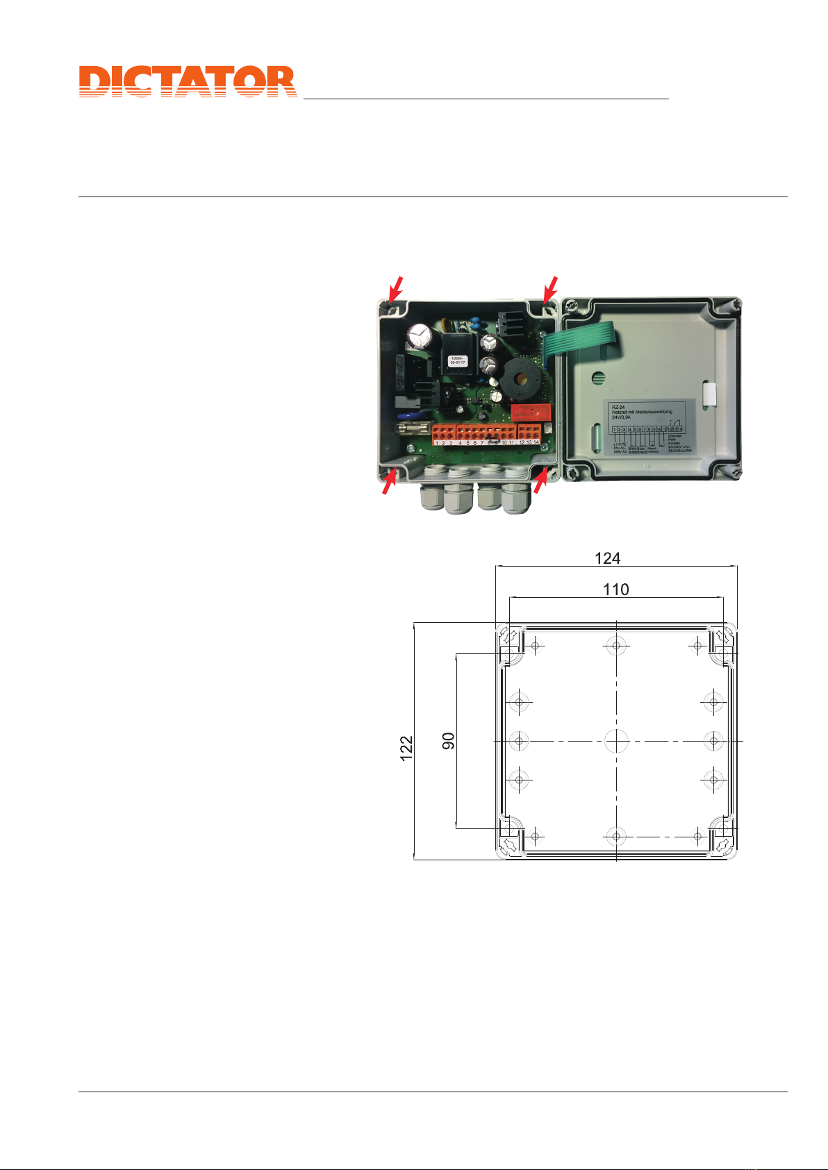
For opening the casing, you turn
each of the 4 spring-loaded screws
(1) about 90° anticlockwise.
Now the cover can be opened to
the right (on the right side (2) it is
connected to the casing).
ATTENTION: When opening the
cover, make sure not to damage the
connection film (3) between casing
and cover and the flat cable (4) to
the membrane keys (see illustration
2 on the following page).
4. Mounting the RZ-24 Central
Ill. 1: Casing of RZ-24 central
4b) Opening the Casing
The RZ-24 central is the power supply with integrated tripping device of
the DICTATOR hold-open system on fire doors, smoke evacuation flaps
etc. also in hazardous areas.
When using the RZ-24, it is mandatory to respect in addition to the re-
gulations for hazardous areas also the regulations of the general type
approval Z-6.500-2443.
The RZ-24 central itself is not ex-proof and therefore must be moun-
ted outside the hazardous area.
When choosing the mounting place, please make sure that
- the indications on the cover of the casing are clearly visible,
- the keys can easily be reached,
- the warning of the horn can well be heard.
Furthermore you have to pay attention to the IP rating of the casing which
is required for the choosen mounting place.
By default the casing of the RZ-24 central has 4 borings with M16 thread
for the included cable inlets IP 64. When these are used, the whole casing
corresponds to the IP rating IP 64 (when mounted with the cable inlets
pointing downwards!).
IMPORTANT: After mounting, all not used cable inlets have to be closed
professionally according to the required protection type (blind plugs)!
4a) Choosing the Place of
Installation
© DICTATOR Technik GmbH • Gutenbergstr. 9 • 86356 Neusäß • Germany
Tel. +49(0)821-24673-0• Fax+49(0)821-24673-90 •E-mail info@dictator.de • 20220325 Page 07.021.9
Technical Manual
RZ-24 Central
(3)
(4)
4c) Fixing the RZ-24 For fixing the casing features 4 borings Ø 5 mm which are accessible
when the cover is open (see ill. 2 and 3.
Mounting the RZ-24 Central - cont.
Ill. 2
Ill. 3

© DICTATOR Technik GmbH • Gutenbergstr. 9 • 86356 Neusäß • Germany
Tel. +49(0)821-24673-0• Fax+49(0)821-24673-90 •E-mail info@dictator.de • 20220325Page 07.021.10
Technical Manual
RZ-24 Central
5. Electrical Connection and Installation of an Ex-Proof
Hold-Open System with RZ-24
Dimensions 122 x 124 x 55 mm (height x width
x depth)
Supply voltage 85 VAC - 265 VAC, 50/60 Hz
Power consumption about 30 W
Additional switching contact potential-free contact 8 A/<250 V~/
AC1 (relay fallen off = tripping)
Secondary output voltage 24 VDC ±5 %
Secondary total load 0.9 A (supply of fire detectors, electro-
magnets and other consumers)
Operating temperature -25 °C to +40 °C
Relative air humidity up to 50 % at 40 °C
temporaily up to 95 % at 25 °C
Casing plastic casing in ABS, light grey,
with 4 threads M16 for cable inlets
Power consumption of the
detection loop alarm: I > 12 mA
interruption: I < 3 mA
short circuit current: max. 50 mA
quiescent current: 4.5 mA
line tension: Ulin = 20.5...21.4
LEDs on the cover of the
casing green LED is on: no fire alarm, system
works normal.
red LED is on: there is a fire alarm or
an error in the detection loop.
IP rating IP 64 when IP 64 cable inlets are used
5a) Technical Data
RZ-24
IMPORTANT: In total the RZ-24 central provides 0.9 A for the supply
of the connected fire detectors, magnets etc.
In case the maximum power consumption is exceeded, the RZ-24 will
automatically switch off. This also happens when it is overheated.
ATTENTION
Some parts inside the casing are
energized with hazardous voltage
during operation! May be opened
only by professionals when being
de-energized (the power supply of
the RZ-24 is cut!!)
© DICTATOR Technik GmbH • Gutenbergstr. 9 • 86356 Neusäß • Germany
Tel. +49(0)821-24673-0• Fax+49(0)821-24673-90 •E-mail info@dictator.de • 20220325 Page 07.021.11
Technical Manual
RZ-24 Central
13 14
Ill. 5a
Zener barrier
Z779**
Ex-proof
hand
release
switch
700232
Max. 20 intrinsically safe
RM 3000IS EX smoke detectors or
WM 3000IS EX heat detectors Resistor 3.9 kΩ
placed in the
last detector
of the line
Up to 12 electromagnets
EM GD 50 EX or EM GD 70 EX
Fuse*
Central
unit
RZ-24 Hazardous area
zones 1 - 2
Safe area
Gas detector*
Screening, optional
(operational earth)
* Each ex-magnet has to be individually fused, with the fuse installed upstream of the magnet. You can find more in-
formation in the manual of the magnets. On site, the integration of a gas warning system must be checked by the ATEX
representative on the basis of explosion protection guidelines.
** Please refer to the Zener barrier manual for the detailed connection diagram.
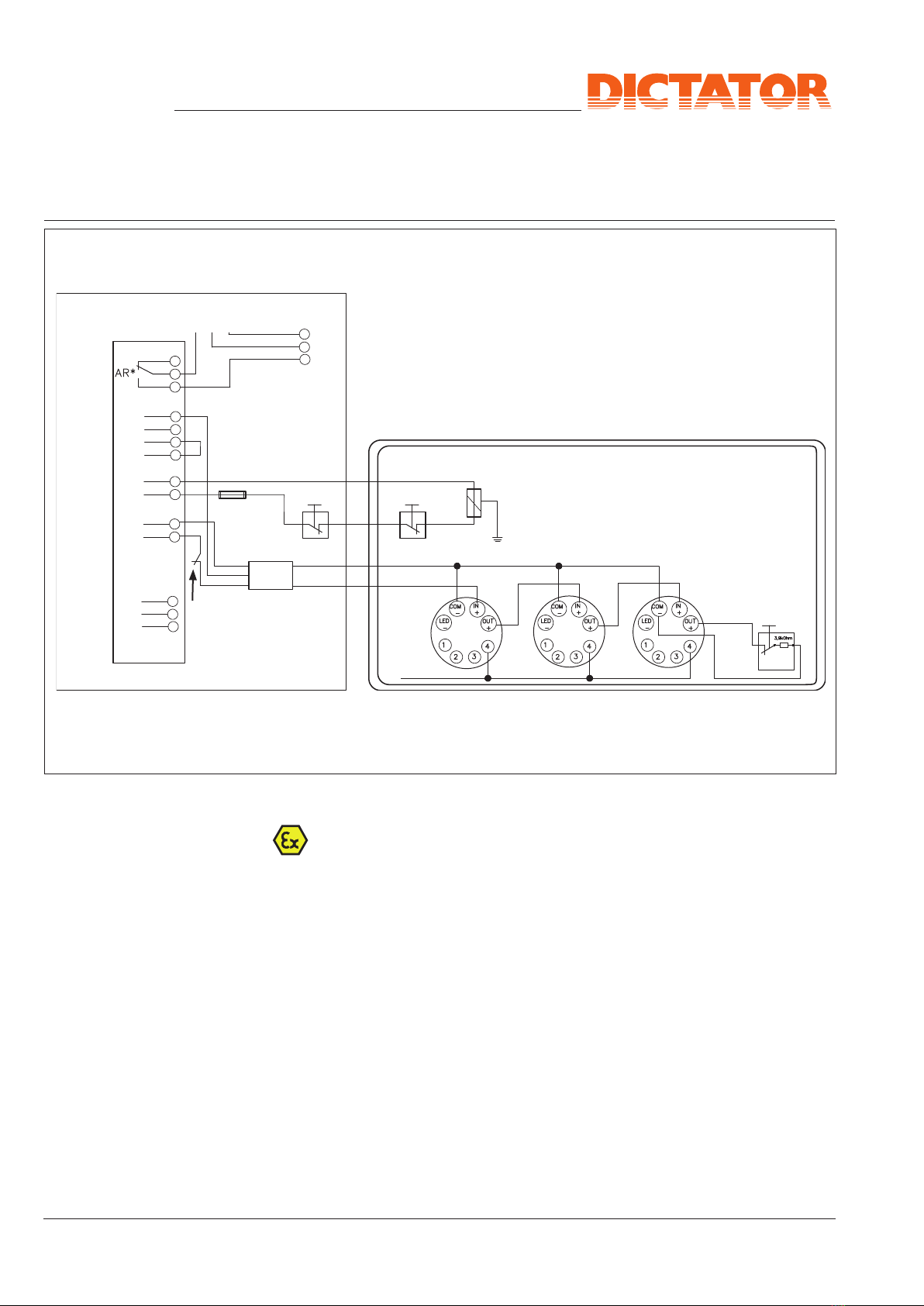
5b) Block Diagram
L1 N P + - +24 - +24 - 8A/250V~/AC1
Mains voltage Fire Hold-open Jumper Supply
85 V AC.... alarm system placed of other
265 V AC loop in factory consumers
(230 V AC)
Fire alarm
potential-free
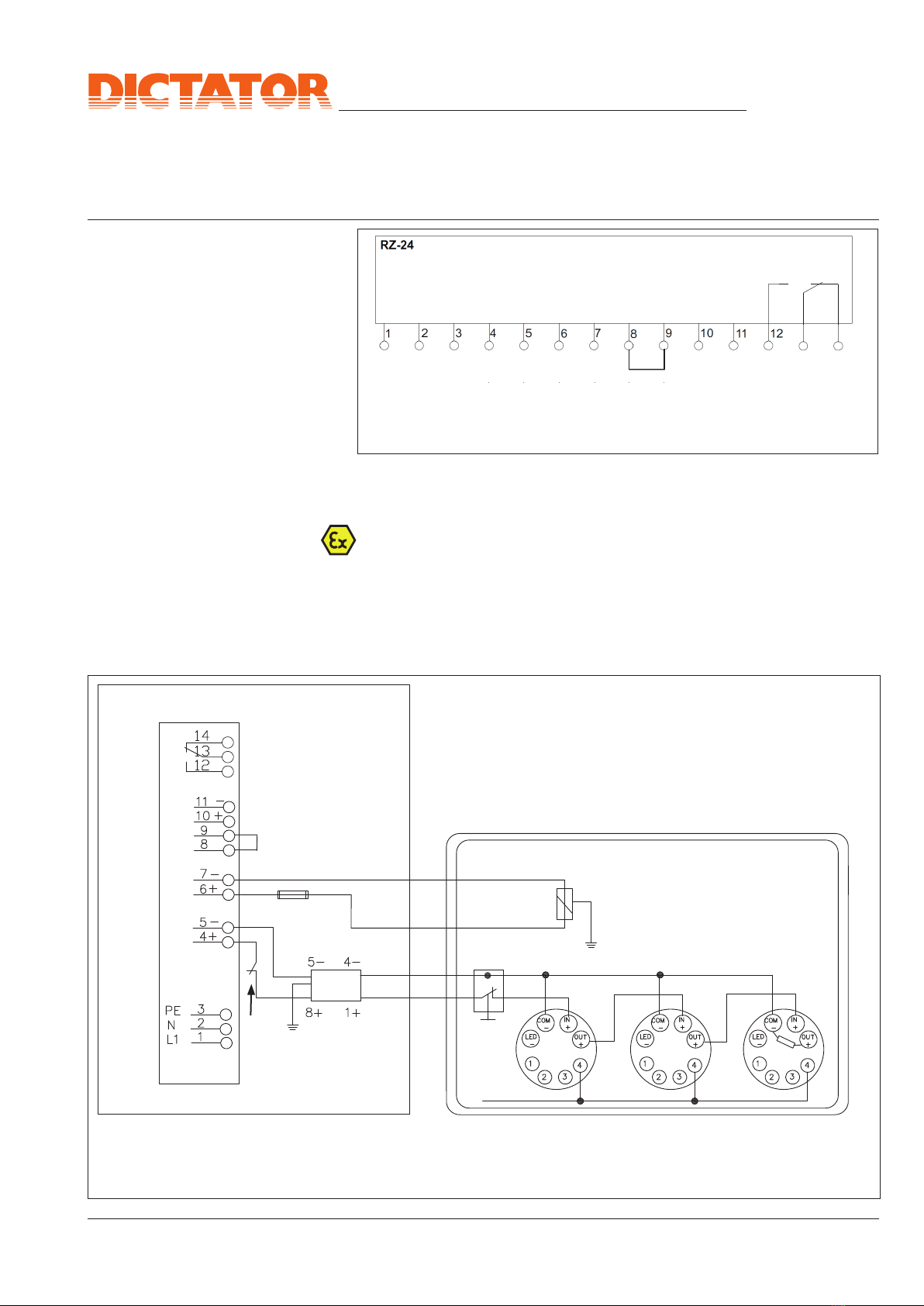
5c) Wiring Diagram RZ-
24 in an Ex-Proof
Hold-Open System
Without
Door Operator
The following wiring diagrams apply when the components of point 3a
are used. If for example other fire detectors (e.g. for installation outside
the hazardous area) are used, please contact us.
A hand release switch mounted outside the hazardous area, has to
be connected so that the Zener barrier is placed between it and the
hazardous area.
ATTENTION: The bridge between the terminals 8 and 9,
which is put in factory, may not be removed!
Ill. 4
Electrical Connection and Installation of an Ex-Proof
Hold-Open System with RZ-24 - cont.
© DICTATOR Technik GmbH • Gutenbergstr. 9 • 86356 Neusäß • Germany
Tel. +49(0)821-24673-0• Fax+49(0)821-24673-90 •E-mail info@dictator.de • 20220325Page 07.021.12
Technical Manual
RZ-24 Central
7
* Each ex-magnet has to be individually fused, with the fuse installed upstream of the magnet. You can find
more information in the manual of the magnets.
On site, the integration of a gas warning system must be checked by the ATEX representative on the basis of
explosion protection guidelines.
** Please refer to the Zener barrier manual for the detailed connection diagram.
Ill. 5b
Zener barrier
Z779**
Ex-proof hand
release switch
700232
with resistor
3.9 kΩ
Max. 20 intrinsically safe
RM 3000IS EX smoke detectors or
WM 3000IS EX heat detectors
Up to 12 electromagnets
EM GD 50 EX or EM GD 70 EX
Fuse*
Central
unit
RZ-24
Hazardous area
zones 1 - 2
Safe area
Screening, optional
(operational earth)
Electrical Connection and Installation of an Ex-Proof
Hold-Open System with RZ-24 - cont.
Gas detector*
© DICTATOR Technik GmbH • Gutenbergstr. 9 • 86356 Neusäß • Germany
Tel. +49(0)821-24673-0• Fax+49(0)821-24673-90 •E-mail info@dictator.de • 20220325 Page 07.021.13
Technical Manual
RZ-24 Central
7
Ill. 6a
Zener barrier
Z779**
Central
unit
RZ-24
Up to 12 electromagnets
EM GD 50 EX or EM GD 70 EX
Max. 20 intrinsically safe
RM 3000IS EX smoke detectors or
WM 3000IS EX heat detectors
Resistor 3.9 kΩ in
the last detector
of the line
Ex-proof hand
release
switch
700232
Gas detector*
Safe area
Hazardous area zones 1 - 2
If necessary,
2 ex-proof
CLOSE switches
Fuse*
Screening, optional
(operational earth)
* Each ex-magnet has to be individually fused, with the fuse installed upstream of the magnet.
You can find more information in the manual of the magnets.
On site, the integration of a gas warning system must be checked by the ATEX representative
on the basis of explosion protection guidelines.
** Please refer to the Zener barrier manual for the detailed connection diagram.
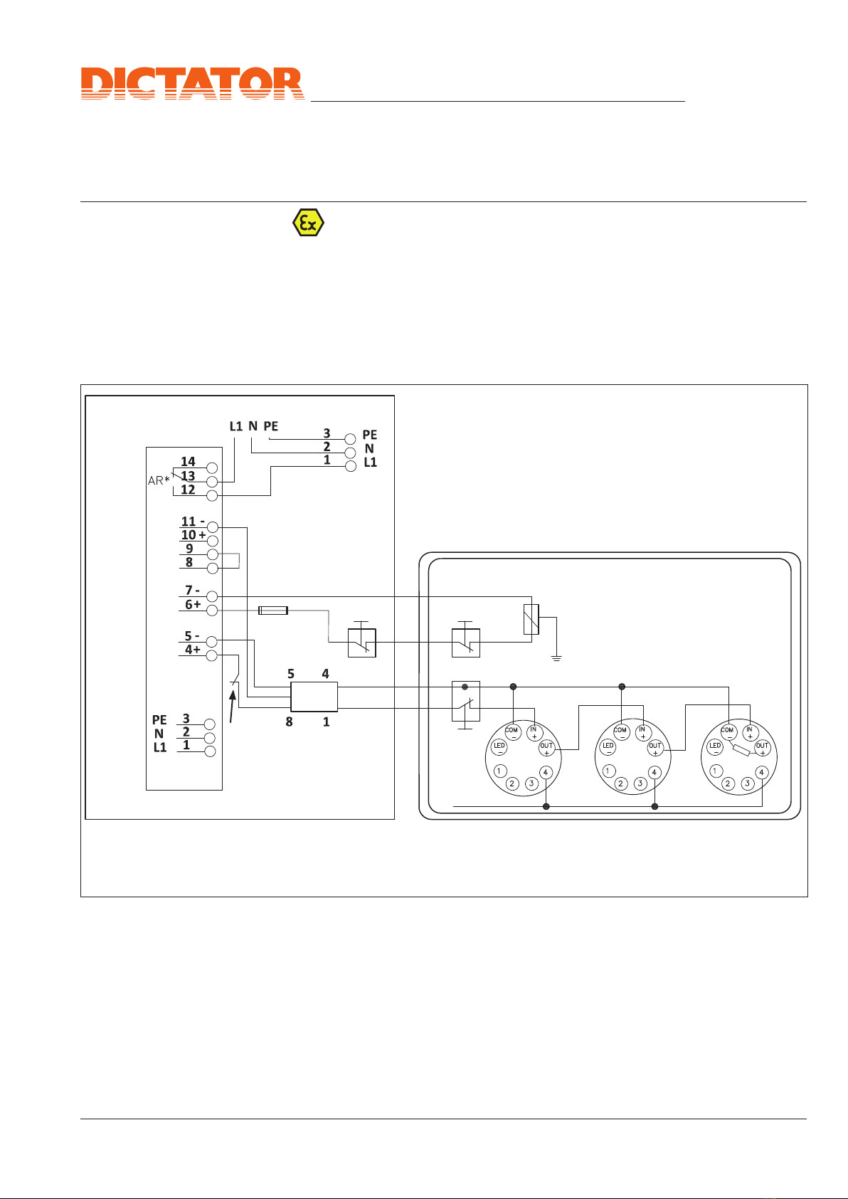
230 VAC
supply of the door
operator controller
AR* = cutoff relay
for door operator
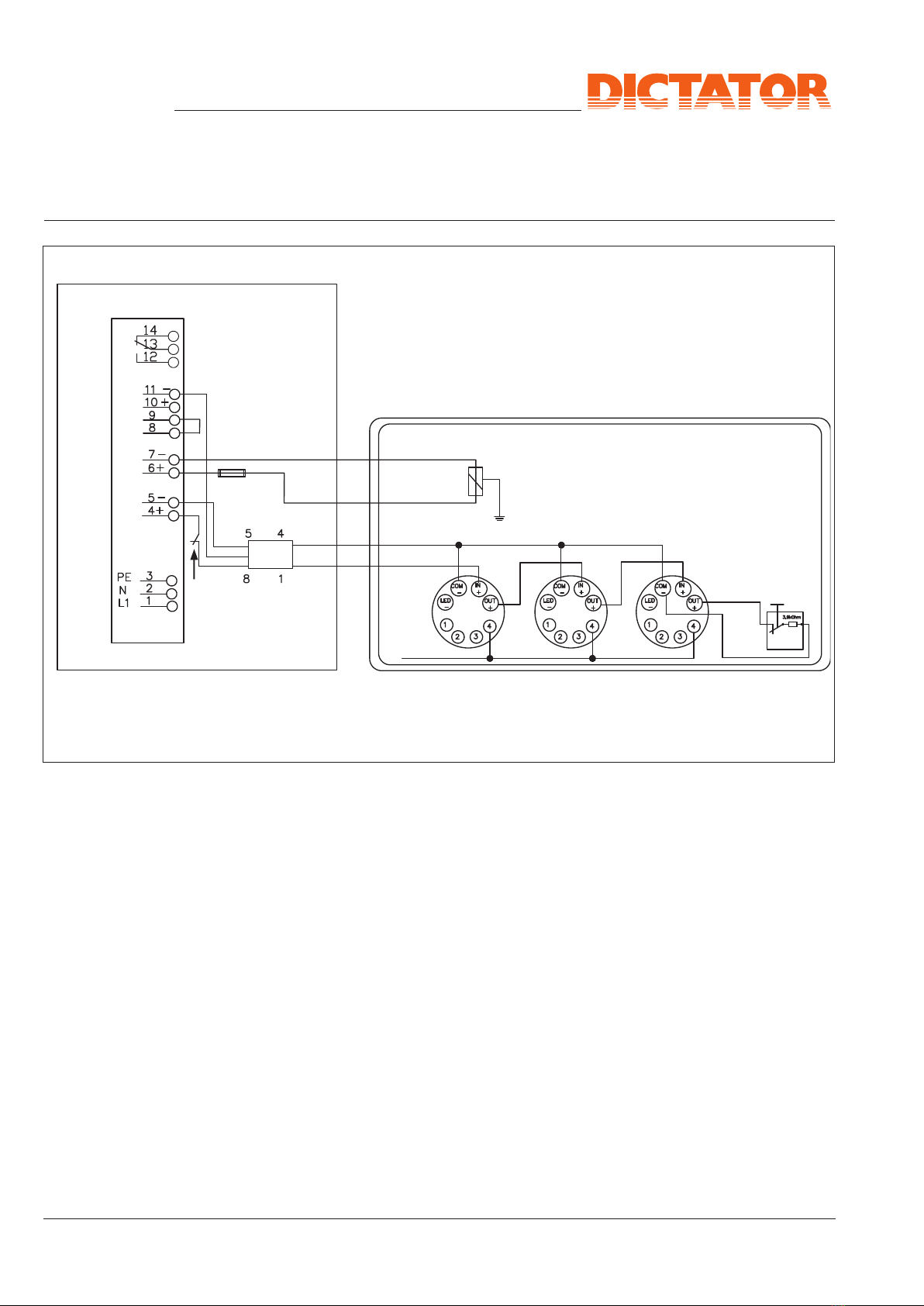
5d) Wiring Diagram
RZ-24 in an Ex-Proof
Hold-Open System
With Door Operator
for Opening
The following wiring examples apply when the components of points 3b
and 6 are used. If for example other fire detectors (e.g. for installation
outside the hazardous area) are used, please contact us.
A hand release switch mounted outside the hazardous area, has to
be connected so that the Zener barrier is placed between it and the
hazardous area.
IMPORTANT: In case of an alarm the RZ-24 will completely electrically
isolate the control system of the door operator!
Electrical Connection and Installation of an Ex-Proof
Hold-Open System with RZ-24 - cont.
© DICTATOR Technik GmbH • Gutenbergstr. 9 • 86356 Neusäß • Germany
Tel. +49(0)821-24673-0• Fax+49(0)821-24673-90 •E-mail info@dictator.de • 20220325Page 07.021.14
Technical Manual
RZ-24 Central
14
13
12
7
6
5
4+
1+
8+
-
-
4-
5-
+
3
2
1
L1
N
PE
9
11
10 +
-
L1 NPE 3
2
1L1
N
PE
8
7
The detection line and the tripping line are energized with low voltage.
Admissible laying systems are surface type with nail clamps, adhesive
clamps or spacing clamps, in open or closed tubes, cable ducts and
profile rails and flush type in slots or tubes.
For cabling you need:
a. Fire detection line: e.g. Ölflex EB 2x0.75 mm2
Mark intrinsically safe current circuits light blue and lay them sepa-
rately (see DIN EN 60079-14).
b. Hold-open system: see description of the ex-proof electromagnets
c. Power line: NYM-J 3x1.5 mm2
5e) Cable Installation
Zener barrier
Z779**
Ex-proof hand
release switch
700232 with
resistor 3,9 kΩ
Max. 20 intrinsically safe
RM 3000IS EX smoke detectors or
WM 3000IS EX heat detectors
Up to 12 electromagnets
EM GD 50 EX or EM GD
70 EX
Fuse*
Central
unit
RZ-24
Hazardous area zones 1 - 2
Safe area
Gas detector*
Screening, optional
(operational earth)
If necessary,
2 ex-proof
CLOSE switches
Ill. 6b
230 VAC
supply of the door
operator controller
AR* = cutoff relay for
door operator
* Each ex-magnet has to be individually fused, with the fuse installed upstream of the magnet.
You can find more information in the manual of the magnets.
On site, the integration of a gas warning system must be checked by the ATEX representative
on the basis of explosion protection guidelines.
** Please refer to the Zener barrier manual for the detailed connection diagram.
Electrical Connection and Installation of an Ex-
Proof Hold-Open System with RZ-24 - cont.
© DICTATOR Technik GmbH • Gutenbergstr. 9 • 86356 Neusäß • Germany
Tel. +49(0)821-24673-0• Fax+49(0)821-24673-90 •E-mail info@dictator.de • 20220325 Page 07.021.15
Technical Manual
RZ-24 Central
13 14
7
6
5
4
3
2
1
L1
N
PE
9
8
11
10
14
13
12
Abschirmung
Zentrale RZ-24 RM 4000 oder
WM 4000 mit
Standardsockel
Elektrohaftmagnet(e)
Handauslöse-
taster
Widerstand
3,9 k:im letzten Melder
Abschirmung
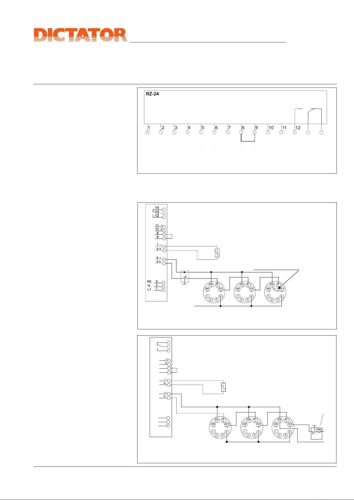
6b) Wiring Diagram
RZ-24 in a Hold-Open
System Without
Door Operator
The following wiring examples apply when the components of point 3c
are used.
6a) Block Diagram
L1 N P + - +24 - +24 - 8A/250V~/AC1
Mains voltage Fire Hold-open Jumper Supply
85 V AC.... alarm system placed of other
265 V AC loop in factory consumers
(230 V AC)
Fire alarm
potential-free
Ill. 7
6. Electrical Connection and Installation of a Hold-
Open System with RZ-24
Electromagnet(s)
RZ-24 central
RM 4000 or WM 4000
with standard base
Screening, optional
(operational earth)
Hand release
switch
Resistor 3.9 kΩ
in the last detector of the line
Ill. 8a
Ill. 8b
Hand release
switch
RM 4000 or
WM 4000 with
standard base
Resistor 3.9 kΩ
Electromagnet(s)
Screening, optional
(operational earth)
RZ-24 central

© DICTATOR Technik GmbH • Gutenbergstr. 9 • 86356 Neusäß • Germany
Tel. +49(0)821-24673-0• Fax+49(0)821-24673-90 •E-mail info@dictator.de • 20220325Page 07.021.16
Technical Manual
RZ-24 Central
7
6
5
4
3
2
1
L1
N
PE
9
8
11
10
14
13
12
L1 N PE
1
2
3PE
N
L1
7
6
5
4
3
2
1
L1
N
PE
9
8
11
10
14
13
12
L1 N PE
1
2
3PE
N
L1
AR*
AR*
Resistor 3.9 kΩ
in the last detector of the line
RZ-24 central
Electromagnet(s)
Hand release
switch
Resistor 3.9 kΩ
230 VAC supply of the
door operator controller
AR* = cutoff relay
for door operator
230 VAC supply of the
door operator controller
AR* = cutoff relay
for door operator
Ill. 9a
RM 4000 or
WM 4000 with
standard base
CLOSE switch
Screening, optional
(operational earth)
Ill. 9b
RM 4000 or
WM 4000 with
standard base
CLOSE switch
Screening, optional
(operational earth)
RZ-24 central
Electromagnet(s)
6c) Wiring Diagram
RZ-24 in a Hold-Open
System With
Door Operator
The following wiring examples apply when the components of point 3d
are used.
Hand
release
switch
Electrical Connection and Installation of a Hold-Open
System with RZ-24 - cont.

© DICTATOR Technik GmbH • Gutenbergstr. 9 • 86356 Neusäß • Germany
Tel. +49(0)821-24673-0• Fax+49(0)821-24673-90 •E-mail info@dictator.de • 20220325 Page 07.021.17
Technical Manual
RZ-24 Central
(1)
(2)
(3)
Resistor 3.9 kΩ
7. Placing into Operation of the Hold-Open System
- After having connected all components in the RZ-24 central, close the
cover and secure it with the 4 screws.
- Switch on the voltage supply.
When everything has been connected
correctly =>
the horn in the casing will sound,
the red LED (1) on the cover will be
on.
- Reset the fire detection line by
pressing the key RESET (2) on the
cover. The horn will be switched off.
Now the system is ready for
operation.
7a) Steps for Placing into
Operation
7b) Functional Tests,
Approval
When the system is ready for operation, its correct functioning and its
installation according to the regulations has to be stated by an approval
test. Only a correspondingly trained and authorized professional may
effect this approval test.
Extent of the approval test
- Checking whether all installed devices are included in the approval of
the RZ-24.
- Verifying whether the labelling of the installed devices corresponds to
the labelling specified in the approval of the building authorities.
- Checking the interaction of all devices: Tripping by simulating the fire
parameter on which is based the functioning principle of the detectors
(e.g. smoke detectors by aerosol) as well as manually (pressing the
hand release switch on the central and the ones installed beside the
door).
- Checking whether the closure (door etc.) is also released for the
automatic closing if the hold-open system doesn't work (e.g. due to a
power cut or a defect detector, to be simulated by removing a detector
and cutting the 230 V supply of the RZ-24 central).
After the successful approval test, the operating company has to perma-
nently fix a plate of 105 mm x 52 mm in the immediate vicinity of the
closure which has to be provided by the manufacturer of the hold-open
system and reads
Hold-open system
Type approval no. Z-6.500–2443
Approved by
Company logo month/year
Ill. 10
Ill. 11
© DICTATOR Technik GmbH • Gutenbergstr. 9 • 86356 Neusäß • Germany
Tel. +49(0)821-24673-0• Fax+49(0)821-24673-90 •E-mail info@dictator.de • 20220325Page 07.021.18
Technical Manual
RZ-24 Central
(1)
(2)
(3)
(4)
(5)
8. Functioning/Adjusting Instructions RZ-24 Central
-RESETTING the complete hold-
open system after an alarm:
Firstly reset the fire detectors by means
of the hand release key (3) (press the
key > 3 sec.) on the cover ofthe casing
and then use the RESET key (2) on the
central to switch the complete system
again ready for use.
- The integrated horn can be
switched off already before the
RESET of the system by pressing the
key "horn" (4).
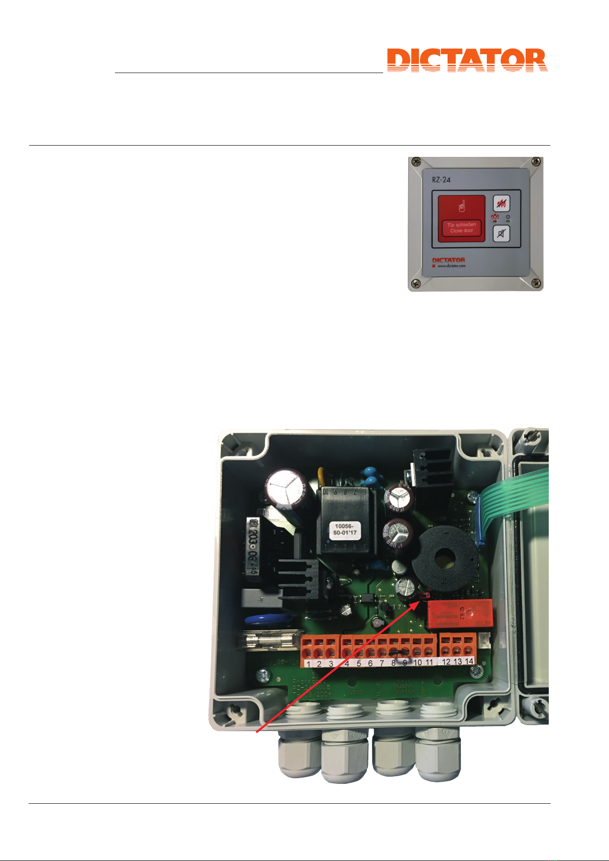
8a) Functions of the
RZ-24
8b) Deactivating the
Integrated Horn
The integrated horn of the RZ-24 can be deactivated, when you don't
want the tripping of a detector to be signalled acoustically. For this pur-
pose simply remove the jumper (5) (DON'T throw it away, but fix it with
adhesive tape to the inside of the cover for a possible later activation!).
Jumper for
activating/
deactivating
the horn
Ill. 12
Ill. 13

© DICTATOR Technik GmbH • Gutenbergstr. 9 • 86356 Neusäß • Germany
Tel. +49(0)821-24673-0• Fax+49(0)821-24673-90 •E-mail info@dictator.de • 20220325 Page 07.021.19
Technical Manual
RZ-24 Central
Status Possible causes Remedy of the error
The RZ-24 control can-
not be reset from the
alarm state.
Terminals 8/9 not
bridged. If there is no external con-
nection, then bridge termi-
nals 8/9.
Fire alarm loop has
no end resistance. Insert a 3.9 kΩ resistor in
the last fire detector.
Open fire alarm loop Check that the fire detectors
are firmly seated in their
base.
Ribbon cable is torn/
defective. Housing must be replaced.
Alarm condition does
not automatically reset
after the manual release
has been operated.
There is a standard
reset board in the
housing.
Install optional reset board
for power failure and fire
(not included in standard
scope of delivery).
The LED on the housing
cover shows red when
the RZ-24 central unit
is in normal operating
mode and it shows
green when the RZ-24
central unit is in alarm
mode.
Defect of the housing
cover of the RZ-24
control unit.
Ribbon cable on the
reset board is not
plugged in correctly.
• Check the ribbon cable
for damage.
• Check the position of
the ribbon cable on the
reset board.
• Check the position of
the reset board on the
main board.
The LED on the housing
cover does not light up
or does not light up pro-
perly.
Ribbon cable on the
reset board is not
plugged in correctly.
• Disconnect the ribbon
cable with the reset
board from the main
board and then recon-
nect it.
• Check the position of
the ribbon cable on the
reset board.
9. Error list
Table of contents
Other Dictator Power Supply manuals

Popular Power Supply manuals by other brands


Thrane&Thrane
Thrane&Thrane TT-6080A installation manual

Altronix
Altronix LPS3AC installation guide

Matsusada Precision
Matsusada Precision CO Series instruction manual

Akyga
Akyga AK-EV-07 user manual

PS Audio
PS Audio PerfectWave Power Plant 5 Owner reference guide

Tecnoware
Tecnoware EVO DSP PLUS TT 15 KVA user manual