Caen ELS BEST User manual

1
BEST
Beamline Enhanced
Stabilization Technology
User’s Manual
All Rights Reserved
© CAEN ELS s.r.l.
Rev. 1.6 –March 2022
BEAMLINE ELECTRONIC INSTRUMENTATION

This product is
certified.
CAEN ELS s.r.l.
Via Vetraia, 11
55049 Viareggio (LU) –Italy
Mail: [email protected]
Web: www.caenels.com

BEST
User’s Manual
3
User Manual –Models –Options –Custom Models
This manual covers the following standard BEST models:
Model
Ordering code
BEST Central Unit
COMP-BEI0004
which includes:
3 Optical Cables - OM2-50/125µm, Multimode Duplex DK-2533-10, length =
10 m;
6 SFP Fiber Optic Transceivers - 4.25Gbps 850nm 3 V ~ 3.6 V LC Duplex
Pluggable - FTLF8524P2BNV
The BEST can be equipped with up to two TetrAMM devices and one PreDAC
device. See their correspondent User’s Manuals for all the ordering codes available.

BEST
User’s Manual
4
Table Of Contents
1. INTRODUCTION .......................................................................................9
1.1 TETRAMM OVERVIEW .................................................................................11
1.2 BEST CENTRAL UNIT OVERVIEW .................................................................12
1.3 PREDAC OVERVIEW.....................................................................................14
2. BEST SYSTEM INSTALLATION..............................................16
2.1 CONNECT THE TETRAMM TO THE PHBPM...................................................16
2.2 CONNECT THE PREDAC TO THE BEAMLINE OPTICS ......................................17
2.3 BEST CENTRAL UNIT PC CONNECTIONS ......................................................18
2.4 BEST SYSTEM INTERCONNECTION................................................................19
2.5 BEST SYSTEM POWER-UP .............................................................................21
3. BEST CENTRAL UNIT OVERVIEW ......................................22
3.1 CONTROLLER SCHEMATIC.............................................................................22
4. BEST LOCAL GUI ................................................................................24
4.1 MAIN WINDOW.............................................................................................24
4.1.1 Graph XY .................................................................................................25
4.1.2 Feedback Control Panel ..........................................................................26
4.1.3 PID Configuration Panel.........................................................................29
4.2 LOGIN ...........................................................................................................34
4.3 BEAMLINE CONFIGURATION .........................................................................35
4.3.1 Beam Position Monitor............................................................................35
4.3.2 Bias Voltage - optional ............................................................................36
4.4 REGION OF CONVERGENCE AND REGION OF INTEREST .................................37
4.1 DAC MANUAL OUTPUT CONTROL ...............................................................38
4.2 PICOAMMETER CONFIGURATION...................................................................39
4.3 SFP INFO ......................................................................................................39
4.4 FREQUENCY ANALYSIS TOOL .......................................................................40
5. EPICS..............................................................................................................42
5.1 EPICS IOC INTEGRATION ............................................................................43
5.2 BEST LOGIN USING EPICS...........................................................................45
5.3 CONTROLLING THE PREDAC OUTPUT IN OPEN LOOP ...................................46
5.4 CONTROLLING THE PREDAC OUTPUT IN CLOSED LOOP: ..............................47

BEST
User’s Manual
5
Document Revision
Date
Comment
0.1.0
April 16th 2014
Document created and edited
1.0.0
July 24th 2014
Main information and features
added
1.0.1
August 18th 2014
Password font corrected
1.1
October 29th 2014
Manual graphics changed
1.2
September 25th 2018
Manual Updated
1.3
October 10th 2019
Added EPICS documentation
1.4
June 3rd 2020
Review of the text
1.5
December 16th 2021
1.6
March 22th 2021
Major text revision and Update.
BEST Local GUI screenshots
taken from version 1.3-6

BEST
User’s Manual
6
Safety information - Warnings
CAEN ELS will repair or replace any product within the guarantee period if the
Guarantor declares that the product is defective due to workmanship or materials and
has not been caused by mishandling, negligence on behalf of the User, accident or any
abnormal conditions or operations.
Please read carefully the manual before operating any part of the instrument
WARNING
Do NOT open the boxes
CAEN ELS s.r.l. declines all responsibility for damages or injuries caused by an
improper use of the Modules due to negligence on behalf of the User. It is
strongly recommended to read thoroughly this User's Manual before any kind of
operation.
CAEN ELS s.r.l. reserves the right to change partially or entirely the contents of this
Manual at any time and without giving any notice.
Disposal of the Product
The product must never be dumped in the Municipal Waste. Please check your local
regulations for disposal of electronics products.

BEST
User’s Manual
7
Read over the instruction manual carefully before using the instrument.
The following precautions should be strictly observed before using the BEST
system:
WARNING
Do not use this product in any manner not
specified by the manufacturer. The protective
features of this product may be impaired if it is
used in a manner not specified in this manual.
Do not use the device if it is damaged. Before
you use the device, inspect the instrument for
possible cracks or breaks before each use.
Do not operate the device around explosives gas,
vapor or dust.
Always use the device with the cables provided.
Turn off the device before establishing any
connection.
Do not operate the device with the cover
removed or loosened.
Do not install substitute parts or perform any
unauthorized modification to the product.
Return the product to the manufacturer for
service and repair to ensure that safety features
are maintained
CAUTION
This instrument is designed for indoor use and in
area with low condensation.

BEST
User’s Manual
8
The following table shows the general environmental requirements for a correct
operation of the instrument:
Environmental Conditions
Requirements
Operating Temperature
0°C to 45°C
Operating Humidity
30% to 85% RH (non-condensing)
Storage Temperature
-10°C to 60°C
Storage Humidity
5% to 90% RH (non-condensing)

BEST
User’s Manual Introduction
9
1. Introduction
The BEST (Beamline Enhanced Stabilization Technology) is a software and
instrumentation suite, which was especially designed to control and stabilize the
intensity (I0) and position (horizontal and vertical) of the photon beam in synchrotron
radiation X-ray beamlines.
The BEST instrumentation building blocks are:
-the readout block –i.e. TetrAMM device;
-the control and interface block –i.e. BEST Central Unit;
-the actuator block –i.e. PreDAC device.
A simplified block diagram of the BEST architecture is shown in the following
figure:
Figure 1: Simplified architecture of the BEST instrumentation suite.
In order to control and stabilize the X-ray it is necessary to determinate the position
and intensity of the beam. For this reason the first building block of the BEST
system is a readout device called TetrAMM, which is a picoammeter instrument
with high sampling speed connected to a phBPM (photon Beam Position Monitor).
Beamline
Control System
BEST Control and
Interface Unit
TetrAMM
Readout
PreDAC
Actuator

Introduction
BEST
User’s Manual
10
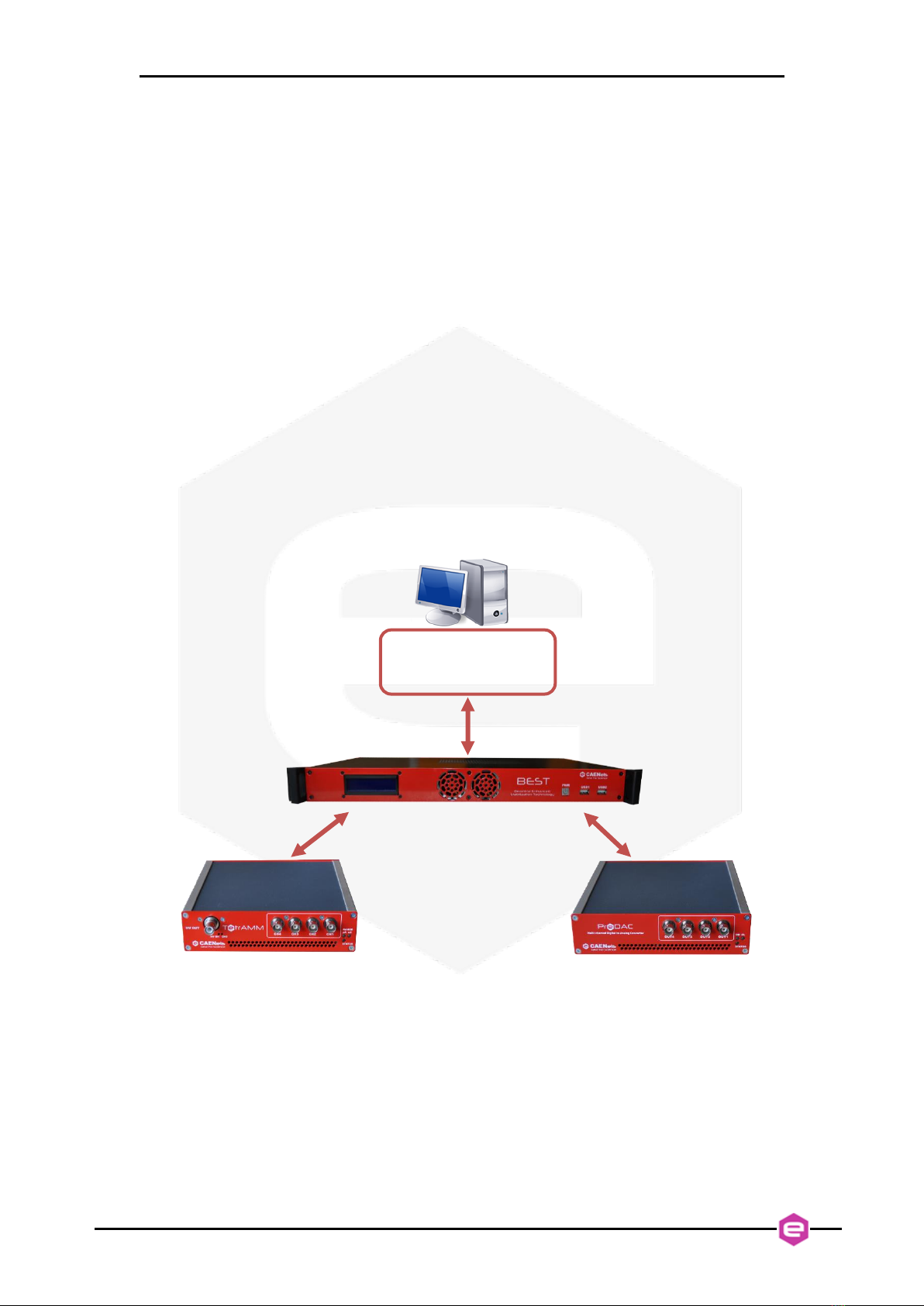
The current from the phBPM are acquired by the TetrAMM and sent to the
BEST Central Unit using a very low latency SFP connection.
The BEST Central Unit takes care of all the calculations to obtain the beam position
and intensity information. The BEST Central Unit calculates the correction
necessary to stabilize the intensity and position of the beam at the desired setpoint,
using a fast PID algorithm. The correction setpoints are then sent to the actuator block
using a low-latency SFP interface. The critical tasks are performed in hardware using
a FPGA device in order to have a deterministic computing time, maximum calculation
speed and high reliability. The X-ray beam intensity is constantly monitored and can
be used to automatically enable or disable the PID controller, by determining if the
beam is ON (intensity higher than a specific threshold) or if the beam is OFF
(intensity lower than a specific threshold). The control and interface unit offers a local
graphical interface (Local GUI), which allows to fully monitor, manage and control
the beam position and intensity. A standard 10/100/1000 TCP-IP Ethernet link allows
remote control and configuration of this system, hence it is possible to connect the
control unit directly to the beamline control system.
The actuator device, called PreDAC, receives the correction/compensation data
calculated by the BEST Central Unit and drives the beamline optics, using its
internal high precision digital-to-analog converters to generate an output voltage
signal capable of driving piezoelectric actuators acting on the optical elements. In this
way it is possible to close the control loop and to stabilize the X-ray beam.
The FPGA-based hardware architecture allows performing the control algorithms at a
maximized speed and with very low latency in order to guarantee full effectiveness of
the BEST correction performance over a frequency spectrum up to several kHz. The
slower and non-critical tasks (i.e. configuration commands) are separately performed
on an embedded industrial PC running a Linux OS with dedicated software.
The distributed architecture was selected in order to maximize the performance, both
in terms of speed as well as of sensitivity and accuracy, of the whole system. The
TetrAMM readout system should be placed as close as possible to the phBPM and
the PreDAC system as close as possible to the actuator driving the beamline optics
in order to reduce the noise pickup on the analog part of the feedback system. The
internal BEST computation and communication between the three system blocks
are all performed in a fully digital way, therefore excluding all additional noise
sources that can strongly affect the controller and stabilization loop performances at
high speed. All three building blocks are interconnected via low-delay fast
communication SFP links running a proprietary protocol. The SFP links on the back
of the BEST Central Unit are directly interfaced to a powerful FPGA board that
performs the position and control algorithms and sends correction values to the DACs
embedded in the PreDAC device.
The BEST system was designed with one of its main focuses on configurability
expandability and flexibility, being able to control and monitor up to two readouts -
TetrAMM devices (i.e. up to 8 picoammeter channels) and one multichannel
actuator - PreDAC device (i.e. up to 4 DAC channels) from one single BEST
central unit.

BEST
User’s Manual Introduction
11
1.1 TetrAMM overview
The CAENels TetrAMM picoammeter is a 4-channel, 24-bit resolution, wide-
bandwidth, wide input dynamic range picoammeter with an integrated optional bias
voltage with bias ratings covering the ±30V up to ±4 kV range. It is composed of a
specially designed transimpedance input stage for current sensing combined with
analog signal conditioning and filtering stages making use of state-of-the-art
electronics. This device can perform bipolar current measurements, which makes it
well suited for extremely low input signals. Low temperature drifts, good linearity and
very low noise levels enable users to perform very high-precision current
measurements.
The TetrAMM is housed in a light, robust and extremely compact metallic box
that can be placed as close as possible to the current source (BPM detector), in order
to reduce cable lengths and minimize possible noise pick-up on the weak signals
coming from the BPM. It is specially suited for applications where multi-channel
simultaneous acquisitions are required, a typical application being the currents readout
from 4-quadrant photodiodes or diamond-based detectors routinely used to monitor
X-ray beam displacements.
The TetrAMM communication to a host PC when used as a standalone unit relies
on a standard 10/100/1000 Mbps Ethernet TCP/IP protocol while its integration with
the BEST (Beamline Enhanced Stabilization Technology) system is performed via
the SFP link placed on the rear panel.
The TetrAMM unit and its I/O connections can be easily seen in Figure 2 (front)
and in Figure 3 (rear).
Figure 2: front view of a TetrAMM unit
Input Channels
High Voltage
output
Measuring range
and status LEDs
High voltage LEDs

Introduction
BEST
User’s Manual
12
Figure 3: rear view of a TetrAMM unit
1.2 BEST Central Unit overview
The BEST Central Unit is a 1U rack-mount system, which houses:
a dedicated hardware with next generation FPGA to perform all the critical
tasks as the system computation and correction calculations and
an industrial PC running Linux OS, which allows overall control and tuning
of the system using a GUI (Graphical User Interface) software.
A dedicated high speed hardware (integrated in the next generation FPGA logic) takes
care of all the critical tasks controlled by the PID algorithm, such as: stabilization,
intensity monitoring and positioning of the photon beam. The FPGA logic receives
the acquired X-ray data from all TetrAMM devices via a high speed SFP link.
The received data (i.e. current outputs from the phBPM) is elaborated to obtain beam
position and intensity information. The FPGA performs also the control PID
algorithms in an optimized way, adding a very low delay to the feedback loop in order
to guarantee the BEST correction performances over the highest possible frequency
spectrum. The computed corrections are sent to the actuator block (the PreDAC
unit) using the SFP interface.
Ethernet and SFP
communication
interfaces
Power Switch
Power and
Configuration
LEDs
Trigger
connectors
Power
connector
Interlocks and
general
input/output
connector
Reset
button

BEST
User’s Manual Introduction
13
The non-critical tasks are, as mentioned earlier, performed in the embedded industrial
PC running a Linux OS. The communication between the PC and the FPGA is
performed trough a PCI Express protocol, therefore all elaborated data and
configurations of the high speed hardware are accessible from the dedicated Linux
graphic software. The BEST Central Unit comes with a user-friendly GUI interface,
which allows to:
configure the BEST system;
configure the system feedback actuation (i.e. PID parameters, detector
configuration);
monitor main physical quantities data (i.e raw TetrAMM currents, beam
position and intensity, FFT, CSP);
control the beam position with a simple “point and click positioning” feature
or by entering a setpoint manually.
Remote control of the Central Unit is also possible using a dedicated EPICS driver
using a standard 10/100/1000 Ethernet link. This provides the possibility to connect
the BEST Central Unit directly to the beamline control system.
The BEST Central Unit and its I/O connections can be easily seen in Figure 4
(front) and in Figure 5 (rear).
Figure 4: Front view of a BEST Control and Interface Unit
Figure 5: Rear view of a BEST Central Unit
Power
button
Industrial PC
USB ports
BEST
Display
Power
connector
Industrial PC
connectors
Dedicated 4 SFP connectors
and 2 triggers

Introduction
BEST
User’s Manual
14
1.3 PreDAC Overview
The PreDAC is a (up to) 4-channel, 21-bit resolution, wide-bandwidth Digital to
Analog Converter (DAC) which is especially designed for seamless operation within
the BEST system. At the core of the PreDAC system there is a high-speed 16-bit
digital to analog converter that uses dithering technique and active low-pass filtering
to obtain a stable high accuracy (21-bit) output signal.
This device is capable of outputing up to ±12 V bipolar voltage with an ultimate
resolution of 12 V –i.e. 21 bits on the bipolar full output range. Output voltage noise
is suppressed using a 4th order active low-pass filter with cut-off frequency (-3 dB) of
10 kHz. Its minimized temperature-induced drifts, good linearity and very low noise
levels enable users to perform high-precision voltage signal generation.
The standard PreDAC has two voltage output channels but can be optionally
upgraded to have three or even four output channels on a single unit. It is housed in a
light, robust and extremely compact metallic box that can be placed as close as
possible to the actuator power driver/amplifier in order to reduce cable lengths and
consequently minimize possible noise pick-up on the analog signal path. It is specially
suited for applications where multi-channel simultaneous actuations are required, a
typical application being control of position (X, Y) and intensity (I0) of the photon
beam in synchrotron radiation or XFEL X-ray beamlines.
The PreDAC communication to a host PC when used as a standalone unit is
guaranteed by a standard 10/100/1000 Mbps Ethernet TCP/IP protocol while its
integration in the BEST (Beamline Enhanced Stabilization Technology) system is
performed via the SFP link available on the rear panel.
The PreDAC unit and its I/O connections can be easily seen in Figure 6 (front)
and in Figure 7 (rear).
Output Channels
ON, CL and
STATUS LEDs

BEST
User’s Manual Introduction
15
Figure 6: front view of a PreDAC unit
Figure 7: rear view of a PreDAC unit
It is very important to limit, when required, the PreDAC voltage outputs in
order to prevent any possible damage to the connected units (for example the
piezoelectric actuators). To perform this task, please refer to the “MIN” and “MAX”
Commands of the PreDAC User’s manual.
Power Switch
Power
connector
Power and
Configuration
LEDs
Trigger
connectors
Interlocks and
general
input/output
connector
Reset
button
Ethernet and SFP
communication
interfaces

BEST System Installation
BEST
User’s Manual
16
2. BEST System
Installation
The following sections describe the various steps to interconnect the BEST
instrumentation.
2.1 Connect the TetrAMM to the phBPM
The first building block of the BEST instrumentation suite is the TetrAMM
picoammeter. This unit is designed to read and convert to digital format the analog
currents from the phBPM (photon Beam Position Monitor). This data is essential to
determinate position and the intensity of the X-ray beam.
The TetrAMM must be connected with the phBPM using the four analog input
connectors placed on the front side of the unit. The BNC connectors are miniature
quick connect/disconnect RF connectors mainly used for coaxial cables. Channel
incremental numbering, as can be seen in Figure 8, is right-to-left (CH1 is to the right
while CH4 is to the left). Please note that the order of the BNC connections with the
phBPM is not important, as the BEST Control and Interface Unit software allows to
freely select the input channel configuration.
Figure 8: BNC input connectors

BEST
User’s Manual BEST System Installation
17
The TetrAMM unit must be placed as close as possible to the analog current
source (e.g. phBPM detector), in order to reduce cable lengths –i.e. cable
capacitance –and to minimize consequent noise pick-up. It is also highly
recommended to use high quality BNC cables to connect the TetrAMM inputs
with the current sources.
Depending on the TetrAMM custom model selected, the TetrAMM can be
equipped with a High Voltage bias module (up to +/- 4kV, monopolar) or with a Low
Voltage bias module (up to +/- 30 V, bipolar). These bias voltage modules can be
used as bias/polarization source for the position-sensing system (e.g.: split ion
chamber, diamond QBPM…). The Low Voltage bias module has a standard BNC
output connector, while the High Voltage bias module has a SHV output connector.
The SHV connector is similar to the BNC but uses a very thick and protruding
insulator (Figure 9). The insulation geometry makes the SHV connector safe for
handling high voltage sources, by preventing accidental contact with the live
conductor in an unmated connector or plug.
Figure 9: High Voltage SHV connector
2.2 Connect the PreDAC to the Beamline
optics
The BEST suite is usually driving several beamline optics units in order to control
and stabilize the X-ray beam at the desired position and with the desired intensity.
This task is performed by the PreDAC device. This unit is designed to control the
piezo/amplifier of the piezoelectric actuators that drive the position of the beamline
optical elements and therefore the position of the X-ray beam. The PreDAC device
is designed to provide maximum flexibility in order to tailor its output to a wide
variety of piezoelectric actuators. The number of PreDAC outputs depends upon
High Voltage
SHV connector

BEST System Installation
BEST
User’s Manual
18
specific beamline characteristics and can be optionally increased from the default
value of two up to four.
The output voltage BNC connectors that must be connected with the driver/amplifier
of the piezoelectric actuators are located on the PreDAC front panel. Channel
incremental numbering, as can be seen in Figure 10, is right-to-left (OUT1 is on the
right while OUT4 is on the left). Please note that the order of the BNC connections
with the piezoelectric units is not important, as the BEST Central Unit software
allows to freely select the output channel configuration.
Figure 10: PreDAC BNC output connectors
The PreDAC unit must be placed as close as possible to the piezoelectric
actuator driver/amplifier, in order to reduce cable lengths –i.e. cable
capacitance –and to minimize consequent noise pick-up. It is also highly
recommended to use high quality BNC cables to connect the PreDAC outputs.
2.3 BEST Central Unit PC connections
The BEST Central Unit allows to monitor and configure the dedicated high speed
hardware using the local GUI, or remotely using EPICS. The software controls the
dedicated hardware through the PCIe interface.
In order to use the Linux OS it is necessary to connect the industrial PC to a mouse,
keyboard and a monitor. There are two additional USB slots on the front side of the
BEST Central Unit. The rear side of the BEST Central Unit (Figure 5) is equipped
with standard PC connections, such as
1
:
1 Display Port
1 HDMI
1 DVI
2 Ethernet
4 x USB 3.0 compliant
1
The PC connections can slightly vary in time since the industrial PC of the Central Unit is kept up-to-
date when newer technologies are widely adopted worldwide.

BEST
User’s Manual BEST System Installation
19
2.4 BEST system interconnection
The TetrAMM and PreDAC units have to be connected with the BEST
Central Unit, which controls the whole system. The communication between the units
is obtained with a dedicated fast speed SFP optic interface.
On the rear panel of the PreDAC and TetrAMM units there is a dedicated SFP
slot providing the communication between the devices and the BEST Central Unit.
Firstly it is necessary to insert the SFP optics transceiver module into the SFP slot
positioned on the rear panel, as shown in Figure 11.
Figure 11: Connection of the SFP optic transceiver into its slot
Remove the caps from the SPF transceiver module from the cable connector and
simply plug the cable connector into the transceiver module as shown in the following
picture:

BEST System Installation
BEST
User’s Manual
20
Figure 12: SFP connection
Note that it is not necessary to connect the Ethernet cable, because the TetrAMM
and PreDAC devices operate as slaves of the BEST Control and Interface unit.
The Ethernet communication is still available, but it operates in read-only mode.
The fiber optic cables from the peripheral devices must then be connected to the
BEST Central Unit. Similar as for the TetrAMM and PreDAC devices the
SFP optic transceivers should be plugged into the dedicated slots on the rear side of
the BEST Central Unit, but in this case the correct orientation of the SFP
transceiver is upside-down.
On the rear side of the BEST Central Unit there are 4 SFP slots. Channel
incremental numbering, as can be seen in Figure 13, is right-to-left (SFP A is the one
the right while SFP D is the one on the left).
Figure 13: BEST Control unit SFP connection
Dedicated 4 SFP connectors
and 2 triggers
Reserved connectors
for future use
SFP A
SFP D
SFP C
SFP B
This manual suits for next models
1
Table of contents
Other Caen ELS Power Supply manuals
Popular Power Supply manuals by other brands

Vector
Vector Start-It Comapct VEC016 Owner's manual & warranty

Et system
Et system EAC-4Q-GS manual

Conductix-Wampfler
Conductix-Wampfler 91008-111-3130923 operating instructions

Nortel
Nortel Passport 8600 Series Installation

Thermaltake
Thermaltake Litepower 400W user manual

TELECO AUTOMATION
TELECO AUTOMATION AL-24-150WNT instructions