Diehl Metering SCYLAR INT 8 User manual

Seite 1 von
71
SCYLAR INT 8
Calculator
Installation and User Guide
for software version F04-004
Diehl Metering GmbH
Industriestraße 13 · 91522 Ansbach · Germania · Telefono +49 981 18 06-0 · Fax +49 981 18 06-615
Am Weimarer Berg 3 · 99510 Apolda · Germania · Telefono +49 3644 84 33-0 ·
[email protected] · www.diehl.com/metering
Subjects to technical alterations 19.02.2019 - EvS

Seite 2 von
71
Contents
1General ................................................................................................. 4
1.1About this Installation and User Guide ...................................... 4
1.1.1Target groups ............................................................................ 4
1.1.2Subject to change, validity ......................................................... 4
1.1.3Completeness ............................................................................ 4
1.1.4Storage location ......................................................................... 4
1.1.5Warning signs ............................................................................ 4
1.1.6Symbols ..................................................................................... 5
1.2Marking ...................................................................................... 5
1.2.1CE marking ................................................................................ 5
1.2.2EC declaration of conformity ...................................................... 5
1.3Copyright .................................................................................... 5
2Safety ................................................................................................... 6
2.1Intended use .............................................................................. 6
2.1.1Misuse ....................................................................................... 6
2.2Basic safety instructions ............................................................ 6
2.2.1Product safety ............................................................................ 6
2.2.2Obligations of operator .............................................................. 6
2.2.3Obligations of trained personnel/user ........................................ 7
2.3Specific hazards ......................................................................... 7
3Product description............................................................................... 8
3.1Mechanical design ..................................................................... 8
3.2Scope of delivery ....................................................................... 8
3.3Labelling ..................................................................................... 9
3.4Functional description ................................................................ 9
3.5Power supply ............................................................................ 10
3.5.1Battery ..................................................................................... 11
3.5.2Overview of the measuring rates ............................................. 11
3.5.3Mains unit ................................................................................ 12
3.6Calculator interfaces ................................................................ 12
3.6.1Communication modules ......................................................... 13
3.6.2Function modules .................................................................... 14
3.7Tariff function ........................................................................... 15
4Technical data .................................................................................... 19
4.1Dimensions .............................................................................. 19
4.2General data ............................................................................ 20
4.3Power supply ............................................................................ 20
4.4Calculator interfaces ................................................................ 20
4.4.1Communication modules ......................................................... 20
4.4.2Function modules .................................................................... 24
4.4.3Test output ............................................................................... 27
5Transport, storage .............................................................................. 29
5.1Unpacking the calculator .......................................................... 29

Seite 3 von
71
5.2Transporting the calculator ...................................................... 29
5.3Storage of calculator ................................................................ 29
6Installation .......................................................................................... 30
6.1Installation ................................................................................ 31
6.1.1. Flow/return setting (optional ex works) .................................... 32
6.1.2.Installing the calculator ............................................................ 34
6.1.3.Connecting temperature sensor ............................................... 38
6.1.4.Installing the temperature sensor ............................................. 40
6.2.Installing extension modules .................................................... 42
6.2.1Display of the slot configuration ............................................... 44
6.3.Connecting modules ................................................................ 46
6.3.1Connecting communication modules ....................................... 46
6.3.2.Connecting function modules ................................................... 48
6.4.Connecting the mains voltage 230 V / 24 V ............................. 49
6.5.Programming the calculator ..................................................... 49
7.Taking into operation .......................................................................... 50
8.Operation ............................................................................................ 51
8.1.Display ..................................................................................... 51
8.2.Operation of calculator ............................................................. 51
8.3.Display indications (default settings) ....................................... 53
9.Maintenance and repair ..................................................................... 63
10.Testing ................................................................................................ 64
11.Removal ............................................................................................. 65
12.Error analysis ..................................................................................... 66
13.Declaration of conformity ................................................................... 67

Seite 4 von
71
1 General
1.1 About this Installation and User Guide
This Installation and User Guide refers exclusively to the SCYLAR INT 8 calculator and is part of the
product. It describes how to use this product safely for the intended purpose throughout the product
life cycle.
1.1.1 Target groups
Operators
The operator must ensure that personnel using the calculator read and observe the instructions given
in this guide and all necessary associated documents, particularly the safety instructions and warning
signs.
Trained personnel/users
Trained personnel must read, observe and follow the instructions given in this guide and the
necessary associated documents, particularly the safety instructions and warning signs.
1.1.2 Subject to change, validity
The information contained in this Installation and User Guide is valid at the time of release of this
version. The version number and release date of this Installation and User Guide are shown on the
back of the document. Changes to this guide are possible at any time.
1.1.3 Completeness
This Installation and User Guide is only complete in conjunction with the relevant associated
documents for the respective application.
1.1.4 Storage location
This Installation and User Guide and all relevant associated documents for the respective application
must be readily available and accessible at all times in the vicinity of the calculator or the overriding
system.
1.1.5 Warning signs
The warning levels indicated by the warning signs are explained below.
Signal word Level of danger Consequences of non-
compliance
DANGER Direct threat of danger Death or serious injury
WARNING Possible threat of danger Death or serious injury
CAUTION Possible dangerous situation Slight injuries

Seite 5 von
71
1.1.6 Symbols
The symbols used in this Installation and User Guide are explained below.
Symbol Meaning
This symbol is the safety sign. All measures marked with the safety sign must be
observed. It is used on warning signs.
This symbol is a safety sign indicating that the ESD (electrostatic discharge)
regulations must be observed. It is used on warning signs. Touching the
electronic components or the connected cable to the meter may damage the
electronics.
This symbol draws attention to information.
This symbol indicates a requirement that must be fulfilled before taking action.
1. , 2. , … These numbers indicate the steps in a sequence of numbered actions.
・ This symbol shows the instructions for avoiding danger in a warning instruction or
an individual step.
1.2 Marking
1.2.1 CE marking
This product bears the CE marking, the metrology marking and the identification number of the notified
body. See Section 3.
1.2.2 EC declaration of conformity
The calculator complies with the directives and standards for MID-approved meters as stated in the
EC declaration of conformity. The EC declaration of conformity contains the number of the EC type
examination certificate. A copy of the EC declaration of conformity can be found at the end of this
document.
1.3 Copyright
© 2015 Diehl Metering GmbH
All rights reserved.
No part of this Installation and User Guide may be reproduced in any form whatsoever (printing,
photocopying or other process) or processed, reproduced or distributed by means of electronic
systems without our written consent. Claims for damages will be asserted in the event of
contravention.
Subject to change.

Seite 6 von
71
2 Safety
NOTE
Observe the following requirements before carrying out work of any kind.
2.1 Intended use
The calculator is used for recording all billing data for local and district heating and cooling.
2.1.1 Misuse
Operation of the calculator outside the specified operating and environmental conditions is not
permitted.
2.2 Basic safety instructions
2.2.1 Product safety
The calculator is produced to the latest state of the art and the recognized safety standards, but the
possibility of danger to the user, adverse effects on the calculator itself or on other property cannot be
ruled out.
Use the calculator only for the intended purpose in a fault-free condition with due regard for
safety and hazards and in compliance with this guide.
Keep this guide and all associated documents in a complete and legible state and accessible
to personnel at all times.
Avoid any kind of work that endangers personnel, persons not involved or third parties.
In addition to the complete documentation, observe all legal or other safety and accident
prevention regulations and the applicable standards and directives in the respective country of
operation.
2.2.2 Obligations of operator
Safe working
The operator of the system is responsible for ensuring that the calculator is used only for the intended
purpose with due regard for safety and hazards and in compliance with this Installation and User
Guide.
The operator must ensure and monitor compliance with the following:
that the meter is used for the intended purpose
legal and other safety and accident prevention regulations
applicable standards and directives of the country of operation
The operator must provide safety equipment.
Personnel qualifications
The operator must ensure that personnel working on the calculator have read and understood this
Installation and User Guide and all associated documents, particularly safety and repair instructions,
before commencing work.

Seite 7 von
71
All work must be performed only by technically trained personnel:
installation and repair work
work on the electronic circuits
Safety equipment
Safety equipment must be provided if required.
E.g. install stop valves before and after the connected flow sensor to simplify removal and
installation.
Warranty
Obtain the manufacturer’s approval before carrying out modifications, repair work or changes
during the warranty period.
Use only genuine parts or parts approved by the manufacturer.
2.2.3 Obligations of trained personnel/user
Observe all instructions in the Installation and User Guide and on the device that are relevant
to handling the calculator.
Use safety equipment if necessary.
Always disconnect the calculator from the electrical supply before carrying out repair work.
2.3 Specific hazards
DANGER
Do not touch live parts during installation work.
Risk of serious injuries or death!
The calculator installation is only to be performed by an installation and/or
electrical contractor.
Personnel must be trained in the installation of medium-voltage electrical
equipment (up to 1000 V).
WARNING
Electrostatic discharge.
Risk of damage to calculator and particularly electronic components, for which
no liability is accepted!
Observe the relevant ESD (electrostatic discharge) regulations.
CAUTION
Electric and magnetic fields.
Risk of interference with electronic components in the calculator!
Do not install the calculator or the input/output cables near heavy electrical loads
or their cables.
Maintain the exact separation. This depends on the magnitude of the voltage and
current of these loads.
Consult a suitable expert in the event of doubt.

Seite 8 von
71
3 Product description
3.1 Mechanical design
Fig. A Design of calculator
1 LC display
2 Pushbutton
3 Optical ZVEI interface
4 Laser labelling
3.2 Scope of delivery
The scope of delivery for the standard version includes the following:
Calculator
Wall mounting set incl. fixing material
Installation Guide
Installation kit for temperature sensors
1
3
2
4

Seite 9 von
71
3.3 Labelling
Fig. B Labelling (example)
The meter is labelled using a laser.
1 Conformity mark
2 Year of declaration of conformity
3 Year of manufacture
4 EC type examination certificate number
5 Calculator article number
6 Calculator serial number
7 Calculator data
8 Product name
3.4 Functional description
The calculator is a fully electronic measuring instrument. It is equipped with a data memory that
enables comparison of the previous months’ readings with the current readings. The data measured
by the calculator are shown in the display. The display is provided with various windows as loop
functions that can be called up in succession to display the system information assigned to each
window (e.g. energy amounts, water amounts, current temperatures, maximum values).
The calculator has 6 display loops: main loop, accounting date loop, info loop, pulse input loop, tariff
loop and monthly value loop. The individual loops are described in Section 8 “Operation”. Some
windows in a loop and whole display loops can be deactivated separately to make the window
structure clearer.
Various display windows comprise up to seven displays that change at intervals of 2 – 4 s.
The loops in the display are numbered from 1 to 6 to help the user find his way around quickly.
The main loop is programmed with the current data as default setting, e.g. for energy, volume, flow
rate and other parameters. It is not possible to change the order of the available data.
3
2
1
5
4
6
7
8

Seite 10 von
71
3.5 Power supply
Possible power supplies:
A cell, 3.6 V DC lithium battery, with a lifetime of 11 years (standard version, with radio)
D cell, 3.6 V DC lithium battery, with a lifetime of 16 years
Mains unit 24 V AC
Mains unit 230 V AC
Fig. C Power supplies
1 A or D cell, 3.6 V DC lithium battery
2 Mains unit 24 V AC / 230 V AC
The various power supplies can be changed in the field.
NOTE
The calculator switches automatically to power save mode if the button is not
pressed for approx. 4 minutes. The display is also switched off in this case, but can
be switched on again by pressing the button. Communication is maintained, e.g.
over the M-Bus or the optical interface. The calculator does not switch to power save
mode if an error exists. The error is shown in the display as an error code.
Never connect between two phases if a mains unit is used, as this would destroy the
mains unit. The protective safety cover must be installed at all times. The cable is to
be fused at max. 6 A and protected against manipulation.
Used batteries must be disposed of at suitable collection points.
1 2

Seite 11 von
71
3.5.1 Battery
A 3.6 V DC lithium battery is fitted in the standard version. The battery is not to be charged or short-
circuited. Ambient temperatures below 40 °C extend the life of the battery.
DANGER
There is a risk of explosion if the battery is replaced with the wrong type of
battery.
3.5.2 Overview of the measuring rates
The following table shows the lifetime of the batteries depending on the standard measuring rates.
Customer versions can differ from the standard measuring rates in the measuring rate and battery
lifetime.
DMStandard
(av.Amb.Temp.:22°C)
Battery‐
Lifetime
[anno]
radio
Interval
[s]
measuringrate
(independentfrom
radio)[s]
A‐Cellupto flow Temperature
noradio/noModule 12 ‐
1 16
868MHz 11 180
434MHz 11 180
Quickmode 6,5 12
D‐Cellupto
noradio/noModule 16 ‐
1 4
868MHz 16 12
434MHz 16 12
mains
noradio/noModule nolimit ‐
8Hz. 2
868MHz nolimit 12
434MHz nolimit 12
1: for „moderate“ ambient temperature. Temperature above 35°C reduces the lifetime.
The temperature for storage of the calculator in a warehouse shall be less than 35°C.
The calculation of flow and volume is done every 2 seconds.
After that the display is updated every 2 seconds.
To save energy the calculator tries to do all its operations like metering, calculation and updating
the
display at the same time.

Seite 12 von
71
3.5.3 Mains unit
The mains unit indicates to the calculator if mains voltage is present. If the mains unit fails, the back-
up battery (CR2032) in the mains unit provides the power supply for up to 1 year. This back-up battery
can be replaced if necessary. The LCD readings (on pressing button) and the date and time are still
updated, but none of the measuring functions work, incl. the flow rate measurement. Communication
still functions over the optional M-Bus, RS485 and RS232 modules or the optical interface, but this
reduces the life of the back-up battery. The integrated radio function is switched off in the event of
mains failure.
3.6 Calculator interfaces
The calculator is equipped as standard with a ZVEI optical interface. This is located on the calculator
below the display (Fig. D). This interface can be used for communication with the calculator (using the
IZAR@Mobile2 software) and for checking it.
Communication uses the M-Bus protocol, for which the Bluetooth IZAR OH BT opto head is suitable.
Fig. D Front of calculator
1 Optical ZVEI interface
1
Seite 13 von
71
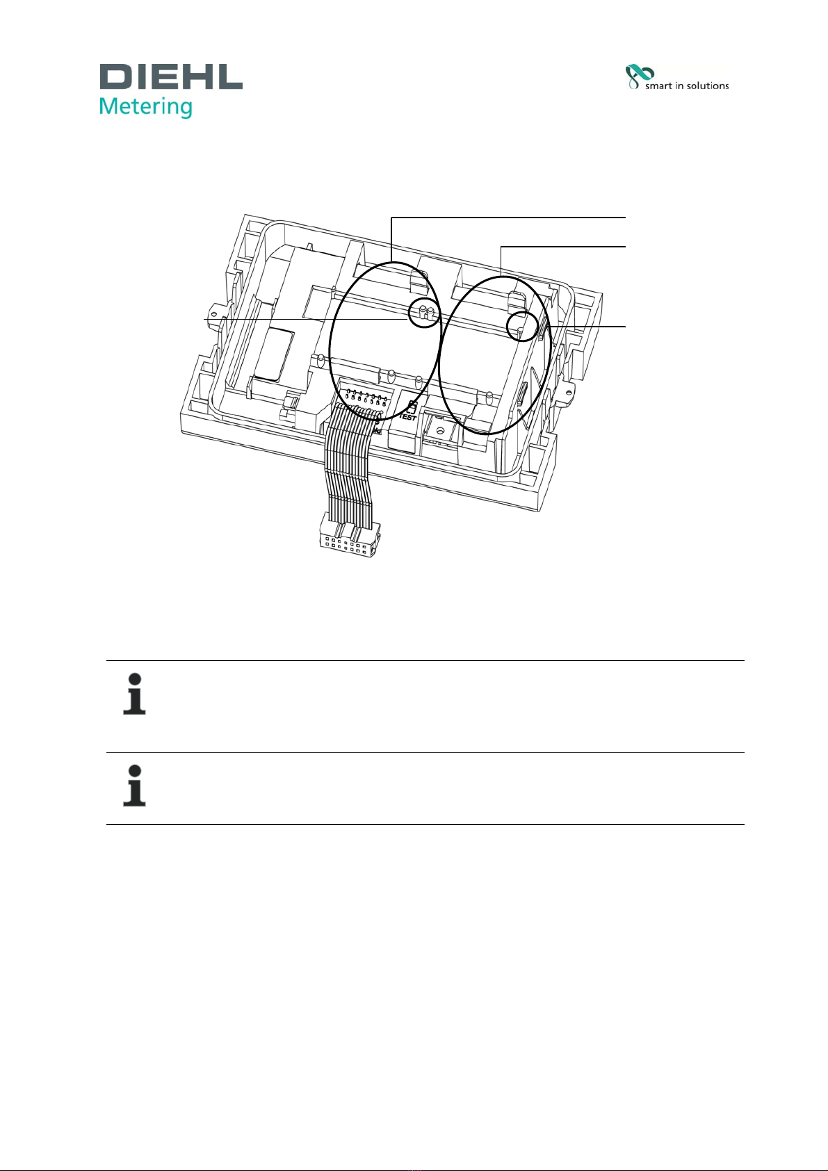
The calculator has two slots for extension modules, slot 1 and slot 2 (Fig. E).
Fig. E Slots
1 Slot 1
2 Slot 2
3 Fixing lugs
NOTE
With L-bus module the internal radio is not available!
The calculator recognizes automatically which module is inserted. This is shown in
the display loop 3 based on a module code. See also point 6.2.1.
NOTE
If other external devices are connected to the calculator, these must be of the safety
extra-low voltage (SELV) type and comply with EN 60950-1.
3.6.1 Communication modules
The calculator supports two communication channels over the same or different interfaces. If the
calculator has an integrated radio, it is possible to use additional the two slots for modules.
The protocol is different for each of the two channels and is preset ex works, but can be set to
customer-specific requirements using the IZAR@Mobile2 software. Each module has its own primary
address. Both modules have one secondary address, which is set to the serial number ex works. The
calculator is equipped with automatic baud rate detection.
M-Bus module
The M-Bus communication module is a serial interface for communication with external devices (M-
Bus control centre), e.g. IZAR CENTER. A number of devices can be connected to a control centre.
Only one M-Bus load is needed. The M-Bus module is electrically isolated.
2
1
3
3

Seite 14 von
71
Communication via radio
The integrated radio function is an interface for communication of predefined protocols with
Hydrometer radio receivers. The communication protocol is preset, but can be defined to a customer-
specific protocol using the IZAR@Mobile2 software. By default, the internal radio is disabled. When
the calculator receives in total 10 pulses for the first time on the volume pulse input, the integrated
radio is enabled.
RS-232 module
The RS-232 communication module is a serial interface for communication with external devices, e.g.
a PC. The transmission speed is 300 or 2400 bauds. A special data cable is required for connecting
this module to the PC. (Order no.: 087H0121). The RS-232 module isn’t electrically isolated.
RS-485 module
The RS-485 communication module is a serial interface for communication with external devices, e.g.
a PC. It can only communicate at a transmission speed of 2400 bauds. The RS-485 module is
electrically isolated.
L-Bus module
The L-Bus communication module is a serial interface for communication with an external radio
module, in which the M-Bus protocol is transmitted. It can be used for example if the radio range of the
internal radio is not enough. The L-Bus module isn’t electrically isolated.
Modbus RTU
The Modbus RTU module ensures a simple integration from SCYLAR INT 8 calculators in to the
Modbus network systems using EIA-485 channel.
LON Works
The LonWorks module is designed for SCYLAR INT 8 calculators for data transmission in the
LonWorks network using the TP / FT-10 physical channel.
3.6.2 Function modules
Pulse output module
This module contains connections for two pulse outputs, which can be programmed as desired using
the IZAR@Mobile2 software. The energy pulse output is marked as standard as “01 - ┴” on the
module and “Out1” in the display. The volume pulse output is marked as “02 - ┴” on the module and
“Out2” in the display. The both pulse outputs are electrically isolated.
Pulse input module
This module has 2 pulse inputs for connecting 2 additional pulse meters, such as water meters, gas
meters or electricity meters. The possibility of programming the pulse value using the IZAR@Mobile2
software enables volume or energy values to be displayed and transmitted remotely over a suitable
communication module. Initial meter counts can also be parametrized for these two pulse inputs. The
pulse input module isn’t electrically isolated.
Module IN-OUT
The Module IN-OUT is equipped with two pulse inputs and a pulse output, which can be programmed
as desired using the IZAR@Mobile2 software. Pulse input 1 is marked “I1 - ┴” on the module and
“IN1” in the display, pulse input 2 “I2 - ┴” on the module and “IN2” in the display. The pulse output is
marked “01 - ┴” on the module and “Out1” in the display. The pulse output on this module isn’t
electrically isolated.

Seite 15 von
71
Analogue module
The analogue module has the size of 2 standard modules and has two passive outputs with 4 to 20
mA. If one analogue module is mounted in the meter, no other module can be installed. The internal
radio is still working. The connection cable between the main pcb board and the module has to be
installed on port 1 (left slot). By default, the two analog outputs are not programmed, the values can
be programmed with the help of the software IZAR@Mobile2 (standard). The analogue module is
electrically isolated.
3.7 Tariff function
The meter has five flexible tariff function.
A tariff is a cumulating register, which starts accumulation after its defined function is valid.
The following tariff unit are selectable:
Energy
Volume
time
Different thresholds are definable for each tariff independently:
Tariff counter 1
Type gate LCD text
T T < Threshold tz000y
T T >= Threshold tz010y
TR TR < Threshold tz001y
TR T
R >= Threshold tz011y
TF TF < Threshold tz002y
TF T
F >= Threshold tz012y
fix enable tz003y
P Power < Threshold tz004y
P Power >= Threshold tz014y
F Flow rate < Threshold tz005y
F Flow rate >= Threshold tz015y
C Based on time tz006y
E External controlled tz007y
Example: t 30K (tz010y) – accumulate power

Seite 16 von
71
The meter accumulate the power to the defined tariff register when the function is
active

Seite 17 von
71
Tariff counter 2..4
Type Gate LCD text
T T < Threshold tz000y
T T >= Threshold tz010y
TR TR < Threshold tz001y
TR T
R >= Threshold tz011y
TF TF < Threshold tz002y
TF T
F >= Threshold tz012y
fix enable tz003y
P Power < Threshold tz004y
P Power >= Threshold tz014y
F Flow rate < Threshold tz005y
F Flow rate >= Threshold tz015y
C Based on time tz006y
E External controlled tz007y
T T < Threshold AND NOT Tariff x-1 enable tz100y
T T >= Threshold AND NOT Tariff x-1 enable tz110y
TR TR < Threshold AND NOT Tariff x-1 enable tz101y
TR T
R >= Threshold AND NOT Tariff x-1 enable tz111y
TF TF < Threshold AND NOT Tariff x-1 enable tz102y
TF T
F >= Threshold AND NOT Tariff x-1 enable tz112y
fix enable AND NOT Tariff x-1 enable tz103y
P Power < Threshold AND NOT Tariff x-1 enable tz104y
P Power >= Threshold AND NOT Tariff x-1 enable tz114y
F Flow rate < Threshold AND NOT Tariff x-1 enable tz105y
F Flow rate >= Threshold AND NOT Tariff x-1 enable tz115y
C Based on time AND NOT Tariff x-1 enable tz106y
E External controlled AND NOT Tariff x-1 enable tz107y
The meter is supporting different count modes.
This function helps to switch on/off the tariff count only, when the meter measuring
results are in a certain quadrant:
Counting dT Flow rate
Energy quadrant 1 + +
Energy quadrant 4 - +
Energy quadrant 2 + -
Energy quadrant 3 - -
Forward energy quadrant 1 + +
Forward energy quadrant 4 - +
Return energy quadrant 1 + +
Return energy quadrant 4 - +
Time counting
Volume counting + +
Volume counting - -
Start tariff accumulation energy, volume or time (named part in the following)

Seite 18 von
71
Arrow Explanation accumulation
blue Total amount (for energy or volume) Total amount of Energy, volume
red part between threshold and T-return Tariff part of Energy, volume, time
green part between T_return and threshold Tariff part of Energy, volume, time
yellow total amount when the T_return is below threshold Tariff part of Energy, volume, time
Formula for e.g. energy:
Ttotal = K’ * m³ * (Tf-Tr)
Ta_Malus = K’ * m³ * (Tr – Threshold)
Ta_Bonus = K’ * m³ x (Threshold- Tr)
Ta_threshold = K’ * m³ * (TF-Tr) when Tr is lower than threshold
K’ - depends on the flow sensor installation - inlet or outlet
time
T
(°C)

Seite 19 von
71
4 Technical data
4.1 Dimensions
Fig. F Dimensions

Seite 20 von
71
4.2 General data
Volume pulse input:
o 0,01…10000 L/Imp.
o 200 Hz max. at pulse duration > 3ms
Temperature sensor:
o PT500/PT100 in 2/4 wire
o There are no wired shortcut necessary
Ambient temperature: 5 … 55 °C
Application:
o heating: 5 … 130°C (150°C)
o cooling: 1 … 90°C
o heating with cooling tariff: 1 … 105 °C
4.3 Power supply
External power supply
230 V AC module / 24 V AC module (Fig. C, item 2, page 10)
Terminals suitable for wires up to 2.5 mm²
Electrical isolation
Frequency 50 Hz
Power consumption 0.12 VA ±10 %
Soldered fuse (50mA)
The cable is to be fused at max. 6A and protected against manipulation.
4.4 Calculator interfaces
4.4.1 Communication modules
M-Bus
M-Bus module to EN 1434-3 standard
2-pole terminal strip with terminals marked “24” and “25”
Terminals suitable for a cable with 2 wires of 2.5 mm²
Electrical isolation
Polarity reversal protection
Maximum voltage: 50 V DC
Current drawn: one M-Bus load
Primary or secondary addressing
Baud rate 300 or 2400 bauds (automatic baud rate detection)
Protocol: M-Bus
max. reading interval at battery supply A-Cell: every 3 minutes*
at battery supply D-Cell: each minutes*
at mains supply: unlimited
* If the calculator is reads more, then the meter recognizes and doesn´t allow it. The display will show
then the error code E - 5. In addition, this error code will be shown in the header of the M- Bus
telegram (to frequent reading via M-Bus).
Fig. G M-Bus module
Other manuals for SCYLAR INT 8
2
Table of contents
Other Diehl Metering Calculator manuals


