Dielectric 2200ST SmartTech Modular Dehydrator Manual
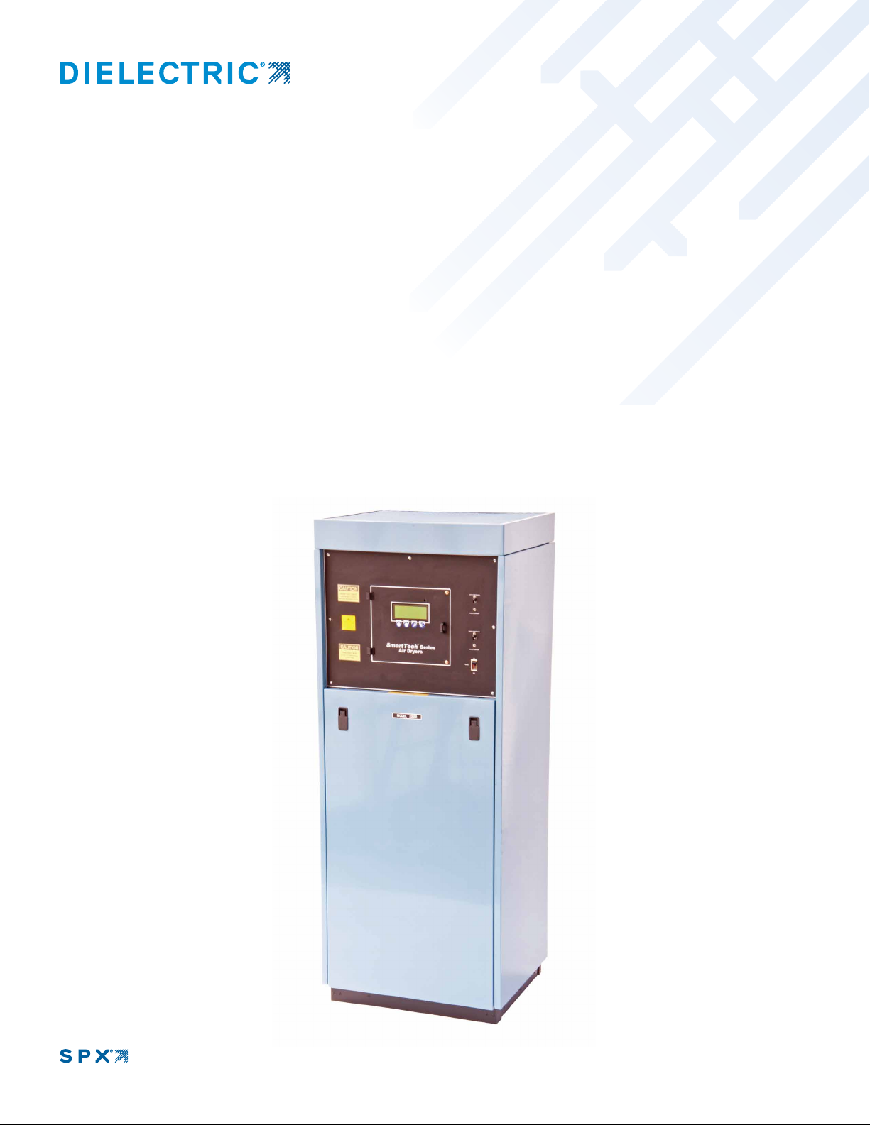
SmartTech Modular Dehydrator
22000ST/33000ST
Instruction and operation manual
MODELS 2200ST / 33000ST SMARTTECH MODULAR DEHYDRATOR IB-430 REV. H PART NUMBER 100436

i
Notes, Cautions, and Warnings herein this manual
are used to prevent personal injury.
Warning: To reduce the risk of fire or electric shock, do not expose this equipment to rain or moisture.
For Indoor use only.
Warning: If the equipment is used in a manner not specified herein, the protection provided by the
equipment may be impaired.
Warning: Turn off Power, Isolate power by unplugging or by locking separate disconnect before ser-
vicing.
Warning!: High Voltage Disconnect Power before working within
Caution: This Unit may start automatically at any time
NOTE: All machinery must be fitted with means to isolate it from electrical energy sources. The iso-
lator must be capable of being locked, when the operator is unable from any of the points to which
he/she has access, to check that the energy is off!
Caution: Use care when lifting compressor as compressor weight exceeds 60 lbs. ( 27.3 kg)
ATTENTION: Observe Precautions for Handling Electrostatic Sensitive Devices
Important Safety Instructions
1.Read and follow all instructions
2.Keep these instruction with the equipment
3.Heed all warnings, cautions and notes.
4.Do not block any ventilation openings.
5.Install in accordance with SPX Dielectric instructions
6.Do not defeat the safety purpose of the grounding type plug
7.Protect the power cord from being walked on or pinched.
8.Use Wrist Strap when handling ESD Sensitive Circuit Boards
WARNING! Risk of Electrocution
Isolate power by unplugging or by locking separate disconnect.
WARNING - RISK OR ELECTROCUTION
WARNING - HOT SURFACE
CAUTION - LIFTING HAZARD
CAUTION - REFER TO ACCOMPANYING
DOCUMENTS
ATTENTION - ELECTROSTATIC SENSITIVE
DEVICE
OBSERVE PRECAUTIONS FOR HANDLING
PROTECTIVE CONDUCTOR TERMINAL

ii
FCC Part 15 Class B Notice
NOTE: This equipment has been tested and found to comply with the limits for a Class B digital
device, pursuant to part 15 of the FCC rules. These limits are designed to provide reasonable
protection against harmful interference in a residential installation. This equipment generates,
uses, and can radiate radio frequency energy and, if not installed and used in accordance with
the instruction manual, may cause harmful interference to radio communications. However,
there is no guarantee that interference will not occur in a particular installation. If this equipment
does cause harmful interference to radio or television reception, which can be determined by
turning the equipment off and on. The user is encouraged to try to correct the interference by
one or more of the following measures:
1. Re-orient or relocate the receiving antenna.
2. Increase the separation between the equipment and receiver.
3. Connect the equipment into an outlet on a circuit different from that to which the receiver is
connected.
4. Consult the dealer or an experienced radio/TV technician for help.
CAUTION: Changes or modifications not expressly approved by the NRTL responsible
for compliance could void the authority to operate the equipment.

iv
TABLE I
TABLE OF CONTENTS
SECTION TITLE PAGE
1.0 Introduction 1
2.0 Feature Descriptions 1
2.1 Display Module 1
2.2 Sensor Module 2
2.3 Alarm/ATS Module 2
2.4 Cabinet Features 2
2.5 Compressor 2
2.6 Heatless Dryer 3
2.7 Humidity Sensor 3
2.8 Passive Air Intake 3
2.9 System Pressure Control 3
2.10 Water System 4
2.11 Optional Water Chiller 4
3.0 Description of Operation 4
4.0 Receiving and Inspection 6
5.0 Location Considerations and Recommendations 6
6.0 Installation 7
7.0 Preparation and Start Up 9
7.8 Post Start Up Observations 9
8.0 Setting and Adjustment Procedures 10
9.0 Scheduled Maintenance 12
10.0 Routine Service Checks 12
11.0 Maintenance Procedures 13
12.0 Alarms and Troubleshooting 15
12.1 Viewing Dryer Alarm Events 15
12.2 The Help Key 15
12.3 Maintenance and the ATS 15
12.4 Clear and Reset Alarm 15
12.5 High and Low Water Shutdown Alarm 16
12.6 High and Low Temperature Shutdown Alarm 16
12.7 Compressor Circuit Breaker Alarm 17
12.8 Power Loss/Brownout Fault Alarm 17
12.9 Humidity Alarm 17
12.10 Low System Pressure Shutdown Alarm 19
12.11 High system Pressure Shutdown Alarm 19
12.12 Low Line Pressure Alarm 19
12.13 High Line Pressure Alarm 20
12.14 ATS Standby Shutdown 20
13.0 Backup Bypass Operation 20
Parts List for 22000ST and 33000ST Models 21 & 22

v
Figure No. Figure Description Page
1 Front view cover
2 Air/Water Flow Schematic 5
3 Front view 23
4 Side view, cabinet open 24
5 Electrical enclosure 25
7 Rear view 26
8 Inside View 27
9 Heat Exchanger/Fan Compartment 28
10 Heatless Dryer 29
11 Purge Solenoid Valves 29
Table Table Description Page
I Tab le of Contents iv, v
II Tab le of Leading Particulars vi
Appendix Description Page
A Alarm Connection Wiring 30
A Alarm/ATS Interface Board 31
A Sensor Board 32
C Front Panel Display Features 34
C SmartTech Menu Block Diagram 35
C Setup Menu Block Diagram 36
D Wiring Electrical Schematic 37
E SmartTech Fusing and Circuit Protection 38
F SmartTech Alarms 39-40
G Power Termination and Grounding 41
H Glossary of Te r ms 42
INCLUDED WITH MODELS 22000ST / 33000ST
Part number Description Quantity
0040151001 Cabinet Air Filter 4
36565 Intake Filter Element (one installed) 2
46222 Water Filter Element (one installed) 2
41125 3/4" NPT Check Valve (refer to Par. 6.5) 1
47744 Back flow check valve 1
0005538032 3/4" NPT Hex Nipple 2
0016853013 3/8" Poly flo 1/4" NPT Fitting 1
MAINTENANCE KITS, PARTS AND ACCESSORIES
100495 12 month maint. kit (contains 2 each of the three types of filters listed above, required
each 12 mo. or 8000 hr.)
100496 24 month maint. kit (contains 2 purge solenoid valve overhaul kits, 1 water eject valve,
and above 12 month kit, required each 24 mo. or 16000 hr.)
46632P Automatic Transfer System is available to provide cycling between two with up to 8
dryers. When equipped with optional communications module, key personnel can
access any Central Office from a remote personal computer via modem, and de -
termine the overall status of the office.
105106 Floor Mounting Bracket Kit for securing Dehydrator Frame to the floor in Earthquake
Zoned Areas.

CHARACTERISTIC MODEL 22000ST MODEL 33000ST
Maximum Output 22,000 SCFD (25960 liters/hour) 33,000 SCFD (38935 liters/hour)
Compressor DC12ST (2 per) DC20ST (2 per)
Electrical Requirement 208-240V, 60Hz, 1Ph 208-240V, 60Hz, 3Ph
Operating Current 26.3 - 22.9 Amps 23.9 - 21.9 Amps
Control Circuit Breaker 3 Amp (2 per) 3 Amp (3 per)
Power Supply Circuit Time-Delayed Fuses 0.5 Amp, 5x20mm (2 per)
3 Amp, 5x20mm
0.5 Amp, 5x20mm (2 per)
3 Amp, 5x20mm (3 per)
Compressor Breakers 20 Amp, 2 pole 20 Amp, 3 pole
Height 71¾" (183cm) 71¾" (183cm)
Width 28¼" (72cm) 28¼" (72cm)
Depth 24" (61cm) 24" (61cm)
Weight 450lbs (204kg) 470lbs (213kg)
*Output characteristics based on standard air conditions of 70°F, 36% RH and 14.7 PSIA.
DRY AIR DEWPOINT Below -40°F. (below -40°C.)
DESICCANT DRYER TYPE DRY-PAK® twin-tower heatless dryer. Efcient, internal check-ball
valving, purge controlled by Two-way solenoid valves.
OPERATING PRESSURE DRY-PAK® and compressor 28 PSIG (193 kPa).
AIR COMPRESSOR TYPE All models are equipped with a direct drive, high capacity, oil-less water
sealed and cooled compressor.
REGULATED LINE PRESSURE Adjustable to 25 PSI (172 kPa)
HUMIDITY ALARM Fixed set point at 5%
LOW LINE PRESSURE ALARM Adjustable to 25 PSI (172 kPa), 8 PSI (55 kPa) Factory Set
HIGH LINE PRESSURE ALARM Adjustable to 25 PSI (172 kPa), 20 PSI (138 kPa) Factory Set
POWER ALARM Active in event of service interruption, compressor or control-circuit
breaker overload or unit turned off manually.
vi
TABLE II
TABLE OF LEADING PARTICULARS*

1
1.0 INTRODUCTION
1.1 This manual provides information to help you
install, operate and maintain the Models 22000ST
and 33000ST Compressor Dehydrators.
1.2 The overall design of the two models is the
same. The difference between them is the size of
their heatless dryer, the horse power and electrical
characteristic of their compressors and their dry air
output capacity. The Model 22000ST operates on
single phase electrical service and has an output dry
air capacity of 22,000 SCFD. The Model 33000ST
operates on 3 phase electric service and has an output
dry air capacity of 33,000 SCFD. All dehydrators
supply an outlet air dew point of -400F. (-400C.) or
lower.
1.3 These models contain several advances in air
dryer design which will be of help to you in operat-
ing and in maintaining them. We recommend that
you review the manual before installation, even if
you are experienced with other designs.
1.4 Particular attention should be given to the start
up procedure. There is a 5 second time delay be-
tween power on and actual start up. Section 2 will
introduce you to the major improvements of the
design. For those familiar with the Dielectric C.O.
dehydrators, Section 2 will refresh your memory
about some helpful characteristics carried forward
to the present models.
1.5 Both models have two high-capacity water-
sealed compressors and a self-regenerating DRY-
PAK heatless drying module that operate well in
harsh environments. However, providing a more
moderate environment will improve performance,
service life and will reduce maintenance require-
ments to a minimum.
2.0 FEATURE DESCRIPTIONS
ITEM SECTION
Display Module 2.1
Sensor Module 2.2
Alarm/ATS Module 2.3
Cabinet Features 2.4
Compressor 2.5
DRY- PAK Heatless Dryer 2.6
Humidity Sensor 2.7
Passive Air Intake 2.8
System Pressure Control 2.9
Water System 2.10
Optional Water Chiller 2.11
2.1 DISPLAY MODULE
2.1.1 The SmartTech™ features an easy-to-read
four line digital display and is backlit for low light
installations. Under normal operating conditions,
the air dryer is continuously displaying System Pres-
sure, Line Pressure, Flow, %RH, Water Temperature
and Air Temperature. Should an alarm occur, this
display will show the primary alarm along with the
date and time the condition occurred. A softkey
Help Menu is available to assist with the diagnosis
of the alarm condition.
2.1.2 Four softkey buttons are used to interface with
the program to change operating parameters as well
as reset alarms and access the Help Menu. The Setup
Menu is used to set Date, Time, Start-up Delay, Line
Pressure Alarms and High Flow Warning. See the
Appendix for detail operation and menuing.
2.1.3 A large tricolored LED indicates the status of
the Air Dryer and functions in the same way as the
ATS 300 IUCs, Flashing Yellow indicates Start-up.
Flashing Green/Yellow indicates Running andAlarm
Disarming, Solid Green indicates Running with
Alarms armed, Flashing Red and Green indicates
Minor Dryer Alarm, Solid Red indicates Major
Dryer Alarm, and Flashing Red indicates Manual
Mode. Manual Mode is used while troubleshoot-
ing, performing maintenance or in an emergency
situation.

2
2.2 SENSOR MODULE
2.2.1 The Sensor Module measures the System
Pressure, Line Pressure, Air Flow, Humidity, and
IncomingVoltage with its onboard sensors. External
sensors for Low Water, High Water, and Water Tem-
perature are wired directly into the sensor board.
2.2.2 The purge valve timing sequence (27 seconds
purge with 3 seconds of dwell) and the cooling fan
control circuits also reside with the Sensor Board.
The fan comes on once the water temperature reaches
90°F otherwise it will be off especially if the optional
Water Chiller Kit (P/N 101961) is installed.
2.3 ALARM/ATS MODULE
2.3.1 This module provides for alarm interfacing as
well as AT S300 connections. (See Appendix A for
additional detail).
2.3.2 Two summary alarm outputs and a 10 alarm
segregation outputs are available for an Alarm
Monitoring system. All outputs are dry contacts
and isolated from one another and may be wired for
open or closed in alarm. The Segregation Alarm is
factory configured for closed in alarm but can be
re-configured for open in alarm by moving two on-
board jumpers. Termination is with dis-connectable
terminal blocks for easy connection and removal.
Summary alarm CO#1 may be configured for 540k
Ohm/270k Ohm and 270k Ohm 0 Ohm Alarms.
2.3.3 Male and female D sub 9 position connectors
are provided for ATS 300/ATS300PLUS bus cable
termination. This interface is built into the module
so no additional external interfacing is needed. An
on-board jumper is used to configure the last dryer
connected. Addressing is accomplished through
Menu-Setup.
2.3.4 A switch for Manual Dryer operation is pro-
vided to place the Dryer off-line with an ATS 300/
ATS 300PLUS Transfer System and allow mainte-
nance and troubleshooting capability. This switch
function is like the one used on the AT S300 IUC
interface panels.
2.4 CABINET FEATURES
2.4.1 The lower front panel of the Dehydrator is
removed by lifting and then turning the two latches.
Each side panel is held by four screws at the rear of
the cabinet. The side panels can be removed when
the screws are loosened. Move the panel sideways
to clear the cabinet and push it forward to remove.
2.4.2 Never place objects on top of the dehydrator. It
will interfere with the air flow of the cooling fan.
2.4.3 The front panel which contains the display
and ON/OFF switch is also the access panel to the
fuses and high voltage components. There is never
a need to open this panel for routine maintenance.
Observe warning labels and always disconnect the
power supply to the dehydrator before opening this
panel.
2.4.4 The cabinet acts as a cooling duct for the
compressors and heat exchangers of the dehydrator.
Excellent cooling is provided when the rear cabinet
air filters are clean and all panels are in place. Do
not operate the dehydrator for long periods with the
panel removed.
- - - NOTE - - -
All machinery must be fitted with means to isolate
it from electrical energy sources.The isolator must
be capable of being locked where an operator is
unable , from any of the points t o w h ich he/she has
access, to check that the energy is still cut off!
An External Surge Protection Device should be
used when operating this device. This Equipment
is suitable for Common or Isolated Bonding and
for Network Telecommunication Facilities and
locations where NEC applies.
2.5 COMPRESSOR
2.5.1 The SmartTech™ Dehydrator has two ST
Watersealed Rotary Air Compressors. These com-
pressors are a higher output capacity over prior
compressor series and features a quick disconnect
vertical manifold for easy removal without the need

3
for removing the air and water hoses. Also a handle
has been added to help with moving and carrying.
2.5.2 Cleanliness of the water system and the air
filters effect the service life of the compressor, as
does the room temperature where the unit is installed.
The most common reason for compressor repair is a
gradual loss of output capacity, until it will no longer
meet the output air requirement of the dehydrator.
Often, continual service is experienced for several
years before overhaul is needed. Ver y long periods
of operation without servicing are not destructive.
2.5.3 We caution against the field repair of electric
motors and recommend that if the compressor needs
more work than a simple repair kit installation, it
should be returned to Dielectric for repair.
2.5.4 Repair kits are easy to install when needed
with the compressor removed from the dehydrator.
Both minor and major repair kits contain a compres-
sor installation procedure P/N 100832.
2.5.5 Performance can be fully restored by instal-
lation of a major repair kit. The compressors in all
models use the same major repair kit (P/N 47328).
2.5.6 The minor repair kit (P/N 47325) will correct
leaks from seals and gaskets, but will not totally
restore full output air flow in compressors which
have lost capacity. The minor repair kit fits all the
models addressed in this manual.
2.6 DRY-PAK HEATLESS DRYER
2.6.1 The dehydrator contains a single, DRY- PAK
heatless dryer module. The DRY-PAK dryer has
two filtered, spring loaded desiccant towers. Air is
directed through the towers by two large check balls
whichare contained withinf r iction-free materials,but
are easily removable for inspection. All manifolding
is internal to the module. The DRY- PAK dryer can
be easily removed or
installed in minutes, without removing other as-
semblies.
2.7 HUMIDITY SENSOR
2.7.1 The humidity sensor is a single chip circuit
that measures both Relative Humidity, and Air
Temperature and signals with a calibrated digital
output. A small sample of dry air from the venting
of system control pressure passes over the sensor.
Its fast response to changes in Relative Humidity
makes it reliable in clearing humidity alarms and
will be much faster compared to the salt sensor
type technology. The sensor boards microprocessor
processes the digital signal and displays % Relative
Humidity and Air Temperature.
2.8 PASSIVE AIR INTAKE
2.8.1 The PassiveAir Intake is designed specifically
for use in central office dehydrators. It performs
several helpful functions and has no moving parts,
requires no maintenance or adjustment. The Passive
Air Intake makes it possible to eliminate moving
parts which have historically required additional
maintenance and trouble shooting.
2.8.2 The Passive Air Intake is a nonrestrictive inlet
air muffler and distributes a mixture of inlet air and
purge air to the compressor. It catches the water
splash when the dehydrator shuts down, so no check
valves are needed, and the dehydrator System Pres-
sure is automatically vented each time it stops.
2.8.3 The Passive Air Intake will catch all the splash
from several shutdowns, one after another, but if you
keep turning the dehydrator off and on, some water
will finally run down the side of the canister. No
naturally occurring situation will cause water loss,
and repeated manual intervention will not cause a
catastrophic failure.
2.9 SYSTEM PRESSURE CONTROL
2.9.1 System Pressure control is very important in
any compressor-dehydrator, because it governs the
quantity of air which the dryer must handle. If the
pressure is too high, the output capacity of the de-
hydrator will be reduced and may not be adequate.
If the System Pressure is too low the dryer will be

4
unable to maintain a low dew point, no matter what
drying method is used.
2.9.2 The Models 22000ST and 33000ST contain
a System Controller which maintains the correct
System Pressure over the full outlet capacity of the
dehydrator. The System Controller interrupts the
outlet air flow during a humidity alarm and bypasses
any surplus when the outlet air requirement is low.
2.9.3 The System Controller reacts to adjustment of
the System Regulator. A System Flow Va lve makes
it simple to obtain the full capacity of the dehydrator
without disconnecting the outlet air pipes.
2.10 WAT ER SYSTEM
2.10.1 It takes about two gallons of clean tap water
to prime and fill the dehydrator water system. Water
is used to cool the compressor and acts to seal the
minute spaces between the port sleeve, the rotor and
the housing. This sealing action is possible because
of the high speed of the rotor. The water also acts
as a lubricant on the rotor seal that separates the
rotating rotor from the fixed housing. The fact that
the water is the medium between the assembled
parts together with a precise balance of mechanical
forces, are the major reasons for the exceptionally
long life of the compressor.
2.10.2 When air is compressed and then is cooled
for use in a dryer, it is usually at or near saturation
(100% relative humidity) regardless of the type of
compressor used. The saturated air is not a problem
to a well designed heatless desiccant dryer. Because
the heatless dryer purges air just as wet as the air
entering it, a balance is maintained over the designed
temperature and flow range.
2.10.3 The components in the water system which
require routine maintenance are the water filter, water
ejector solenoid valve and the water float switches
which are inside the Water Sight Tube.
2.10.4 A “Manual Water Eject Switch” has been
included in the water system to aid in maintenance
and in trouble shooting. The switch is visible when
the front cover is removed. The switch is clearly
labeled and is located on the left side above the air
intake filter.
2.11 OPTIONAL WATER CHILLER (P/N
101961 without flow control valve)
2.11.1 Both models may be equipped with a factory
installed “ Water Chiller”. This option is offered
for those sites where, due to building constraints,
adequate ventilation o r a i r conditioning are not practi-
cal alternatives and multiple dryers are required due
to very high air flow requirements. The necessary
coolant water flow may be provided by a recirculat-
ing cooled water system or by tap water.
2.11.2 The chiller option consists of an efficient flat
plate water-to-water heat exchanger, flow-orifice,
temperature indicator and related components. The
chiller coolant flow is regulated by the flow-orifice.
Termination of the chiller is at the rear of the dehy-
drator cabinet for easy hookup.
2.11.3 The dehydrator water circuit, (see paragraph
3.3), is kept totally isolated from the coolant water.
The warmest water in the dehydrator is cooled by
the chiller before it enters the dehydrators air cooled
heat exchanger and flows to the compressor. The
dehydrators operating environment thus is similar
to its environment when operating in a much cooler
room and its output capacity increases proportion-
ally.
3.0 DESCRIPTION OF OPERATION
3.1 Air/Water Flow System (see Fig. 2)
Ambient air is drawn through the inlet air filter and
through the Passive Air Intake, where it mixes with
purge air returning from the heatless dryer desic-
cant towers.
3.2 The combined wet air then enters the compres-
sors, where the pressure is raised to 28 PSIG and
the air is mixed with the compressor cooling water.
Water enters the compressors at a rate controlled by
the water metering orifices. The compressed air and
warmed water flows directly to the water separator
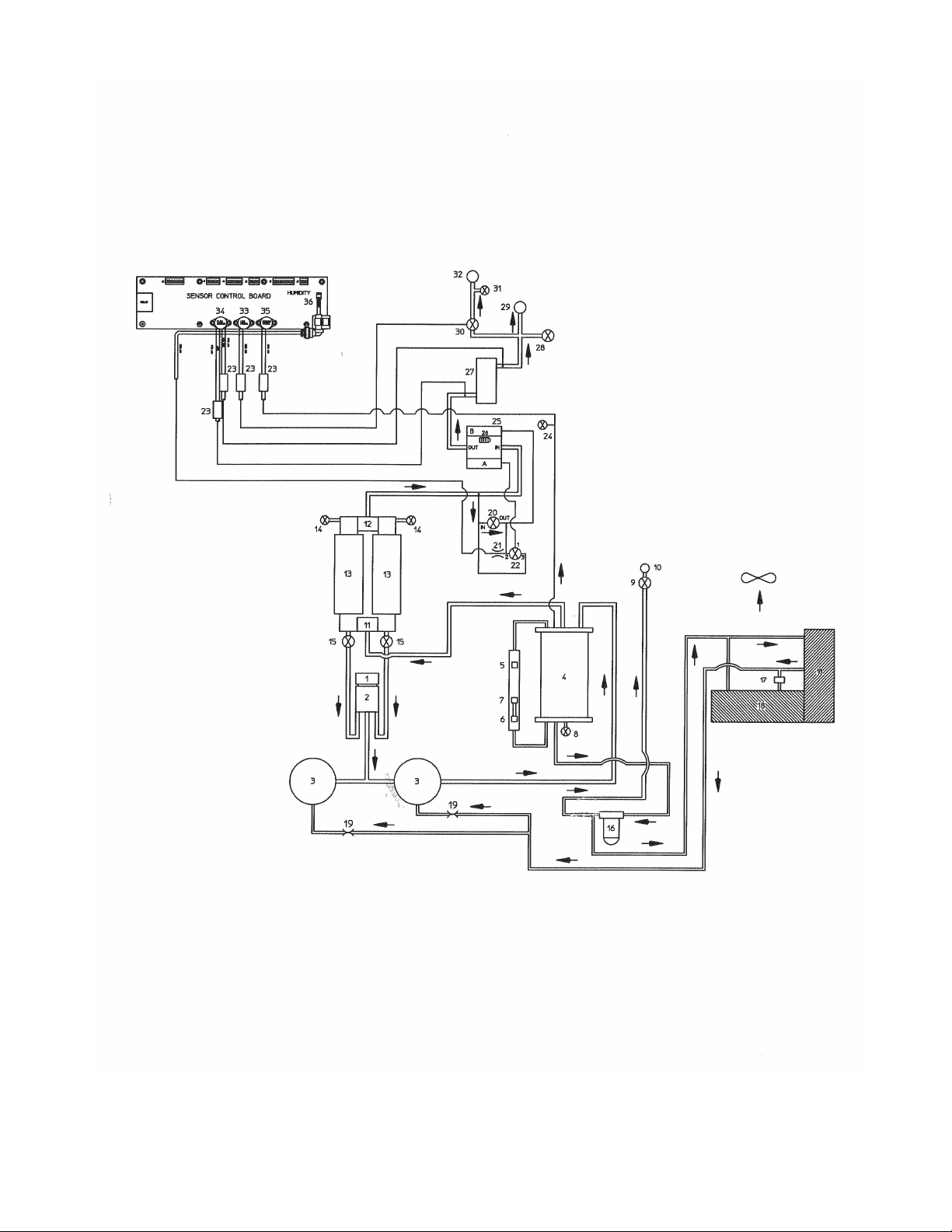
Figure 2
Air/Water Flow Schematic
1) INTAKE FILTER 2) INTAKE DEFUSER 3) AIR COMPRESSORS
4) WATE R SEPARATOR 5) HIGH WAT E R SHUT-OFF FLOAT 6)LOW WATE R SHUT-OFF FLOAT
7) WATE R EJECT FLOAT 8) WATE R DRAIN PETCOCK 9) WATE R EJECT SOL. VA LVE
10) WAT E R EJECT OUTLET PORT 11) DRYING TOWER INLET PORT 12) DRYING TOWER OUTLET PORT
13) DRYING TOWERS 14) DRYING TOWER TEST PORTS 15) PURGE SOLENOID VA LVES
16) WAT E R FILTER 17) THERMISTOR (THERMAL SWITCH) 18) AIR/WAT E R HEAT EXCHANGER
19) WAT E R METERING ORIFICE 20) SYSTEM CONTROLLER REGULATOR 21) HUMIDITY DRY AIR VENT
22) HUMIDITY SHUT-OFF PILOT VA LVE 23) DISCONNECT UNIONS 24) SYSTEM PRESS TEST VALVE
25) SYSTEM CONTROLLER 26) BYPASS AIR MUFFLER 27) FLOW CALIBRATION VALVE
28) SYSTEM FLOW VA LVE 29) HIGH PRESSURE OUTLET PORT 30) LINE PRESSURE REGULATOR
31) LINE PRESSURE TEST PORT 32) LOW PRESSURE OUTLET PORT 33) LINE PRESSURE SENSOR
34) FLOW CALIBRATION SENSOR 35) SYSTEM PRESSURE SENSOR 36) HUMIDITY SENSOR
5

6
tank without any restriction. Inside the separator
tank, centrifugal action and large surface impinge-
ment separate the water from the air stream without
significant pressure change.
3.3 Warm water flows from the base of the tank to
the large water filter where any entrained solids are
removed. The filtered water passes through the air
cooled heat exchangers and is cooled to near ambi-
ent temperature. The termperature is monitored
by a Thermister. The cooled filtered water flows
unrestricted to the water metering orifice and again
into the compressors. The water travels the entire
route in about one minute.
3.4 Moist, pressurized air flows from the top of the
water separator tank to the DRY- PAK dryer inlet
check ball. The check ball is attracted to the open
purge valve (left or right) selected by the cycle timer
(which is part of the sensor board control).
3.5 The moisture content of the process air is re-
duced to a dew point of -400F. (-400C.) or lower, as it
moves upward through the desiccant tower opposite
the open purge valve. Any entrained water droplets
drain into the purge valve fitting below the desiccant
tower. The surplus moisture is retained temporarily
in the desiccant.
3.6 A metered flow of dry purge air passes downward
through the desiccant tower (the desiccant tower
which has an open purge valve), picks up the moisture
retained there in the previous cycle and carries it back
to the Passive Air Intake. The surplus moisture is
added to the water in the system when the purge air
is again compressed (together with ambient air) and
it flows to the water separator tank. The desiccant
tower selection is reversed every thirty seconds of
operation by the cycle timer.
3.7 The addition of surplus moisture to the water in
the separator tank causes the water level in the sight
tube to raise the water ejector float switch. This ac-
tion in turn causes the water ejector solenoid valve to
open and expel the surplus water through the water
drain fitting on the rear of the cabinet.
3.8 Dry air flows from the heatless dryer outlet to
the System Controller, which has a single pressure
adjustment. The System Controller maintains the
System Pressure, and also performs as both a Bypass
Val ve and a Humidity Shut Off Valve. The Bypass
Air Muffler is located directly behind the body
of the System Controller. The System Controller
Regulator is adjustable and controls the pressure
to the system controller. Ven ting dry air from the
regulator controlled by a small fixed orifice is passed
across the humidity sensor to measure the systems
relative humidity. The system pressure is measured
with a pressure sensor located on the Sensor Control
Board.
3.9 The dry air flows next to the factory set flow
valve that has a differential pressure sensor connected
across it. The sensor located on the sensor board,
measures the pressure and displays the corresponding
flow in SCFD based on the calibration and Dryer
size. The dry air is then fed to both the High Pres-
sure Outlet and The Line Pressure Regulator. The
output of the Flow Val ve also supplies the System
FlowValve, which is used when adjusting the System
Pressure Regulator. The Line Pressure Regulator
adjustment controls the pressure which flows to the
Low Pressure Outlet. The air flowing to the Low
Pressure Outlet is monitored by a line pressure sensor
located on the sensor board. High and Low Pressure
Alarms are set in the Setup Menu.
4.0 RECEIVING AND INSPECTION
4.1 You have the responsibility to inform the carrier
of any shipping damage and to initiate any damage
claims. Do not accept containers showing obvious
damage.
4.2 Immediately upon receipt, remove the air dryer
from the shipping container. Thoroughly inspect the
air dryer and file a claim against the carrier for any
hidden damage.
5.0 LOCATION CONSIDERATIONS AND
RECOMMENDATIONS
5.1 All electrical wiring must be in accordance with

7
local electrical codes and emergency power proce-
dures. A 40-amp fused external listed disconnect box
with 8 AWG power cable is required for the models
22000ST and 33000ST. The listed disconnect must
be in close proximity to the Air Dryer and within
easy reach of the operator. Also, the disconnect must
be marked for the Air Dryer connected. A properly
sized switch or circuit breaker must be included in
the building installation. NOTE: Do not position
the Air Dryer so that it is difficult to operate the
disconnecting device.
For 22000ST..208-240V, 26.3-22.9A, 60Hz, 1 Ph
For 33000ST.208-240V, 23.9-21.9A, 60Hz, 3 Ph
A standard 115 VAC wall outlet is recommended
for operation of power tools, drop cord and for a
transfer controller.
5.2 Provide enough space for installation so that
there will be at least 24 inches (more is fine) at the
rear of the dehydrator for ventilation and access.
Allow at least 36 inches at the front and sides for
maintenance access.
5.3 A floor drain is needed to accept the ejected wa-
ter from the water drain fitting. Install the provided
water drain fitting using pipe sealant to the rear of
the cabinet. The drain should be within 75 feet of
the dehydrator. a 3/8-inch diameter plastic tube
needs to be connected to the water drain fitting and
routed to the water drain. The 3/8-inch water drain
tube may be routed over a wall or other obstacles
but it cannot be more than 15 feet above the water
drain outlet port at any time. The drain tube must
not be subjected to freezing or crimping.
5.4 The location should provide adequate space
and ventilation for heat dissipation. The preferred
ambient temperature range is 600F to 900F. Ambi-
ent humidity levels are of little consequence, but a
clean environment prolongs component life. Do
not place the air dryer where it may be subjected
to freezing.
5.5 The unit is practically vibration free and bolting
to the floor is not required. A level floor location
is recommended.
5.6 For models equipped with “Water Chiller” op-
tion only: The 1/4" NPT coolant water inlet and
coolant water outlet are clearly labeled, on the rear
of the cabinet. Make provision for the coolant water
supply and the coolant water drain outlet. The use
of rustproof brass quick connect, automatic shut-off,
couplings (available from Dielectric) together with
flexible hose is recommended. Provide safeguards
against crimping, freezing and drain-back as in-
structed in 5.3 above.
Note: The number references with parenthesis
throughout the remainder of the manual are the
Parts List item numbers and are also the reference
numbers found in pages 21 & 22.
6.0 INSTALLATION
6.1 Position the air dryer in accordance with the
recommendations of Paragraph 5.2.
6.2 Lift and Turn inward the two door latches and
remove the front panel.
6.3 A programmable delayed start time provides a
fixed minimum delay of five seconds, so that the
compressor sealing water will automatically prime
the compressor before each start sequence. If the
dehydrator is to be one of two or more operating at
the same time, the delayed start time on the second
dryer should be programmed with ten seconds of
delay. Go to MENU - SETUP - Power on Delay to
change delay. This will prevent power surges fol-
lowing service interruptions, or when switching to
or from an emergency generator. It is recommended
additional Air Dryers are separated by a minimum
of 5 seconds. See Section 8 for Setup Menu.
6.4 Install a flexible water drain hose as described
in paragraph 5.3. Hold the cabinet fitting with a
second wrench while tightening the tube fitting.
6.5 Make flexible tube connections to the high and
low pressure air outlet fittings (see fig.7 for loca-

8
tion). Two check valves with hex nipple fittings
come packaged with the Air Dryer. If using only
one Air Outlet, install the Check Val ve marked with
P/N 47744 Flow Restrictor Check Val ve label at
the outlet. NOTE: the direction of the large arrow
indicates main airflow. This check valve has been
modified with a small orifice to allow feedback of
dry air into Standby Air Dryers that are on Trans-
fer/Cycling Systems.
6.6 Ver ify that the Power Switch on the front control
panel is in the OFF position. Locate the Alarm/ATS
Interface Board and remove the battery insulation
boot prior to turning on theAir Dryer. SeeAppendix
A for battery location.
WARNING!
RISK OF ELECTROCUTION - Disconnect from
electrical power before starting this proceedure.
- - - NOTE - - -
An External Surge Protection Device should be
used when operating this device. This Equipment
is suitable for Common or Isolated Bonding and
for Network Telecommunication Facilities and
locations where NEC applies.
6.6.1 Instructions for Model 22000ST only:
The 22000ST operates on 208-240 VA C , 1 Ph.
power. Route the power cord (not provided) to a
wall mounted listed electrical disconnect box, or
alternately, install an appropriate twist lock connec-
tor on the cord and install a mating connector at the
wall or on a free-hanging power cord. At the rear of
the air dryer route the cable through the strain relief
and into the power entrance box.
Connect the power cord BLACK lead to L1 of
Terminal Board.
Connect the other BLACK lead (or WHITE lead
with marker) to L2 of the Ter minal Board.
Connect the GREEN lead to the Ground Stud.
(see appendix "G" for proper grounding to the
ground stud).
6.6.2 Instruction for Model 33000ST only:
The Model 33000ST operates on 208/240 VA C , 3
Ph. power. Route the power cord (not provided) to
a wall mounted listed electrical disconnect box, or
alternately, install an appropriate twist lock connec-
tor on the cord and install a mating connector at the
wall or on a free-hanging power cord. At the rear
of the air dryer, route the cable through the strain
relief and into the power entrance box.
Connect the power cord BLACK lead to L1 of
the Terminal Board.
Connect the BLUE lead (or white with blue
marker) to L2 of the Ter minal Board.
Connect the RED lead to L3 of the Terminal
Board.
Connect the GREEN lead to the Ground Stud.
(see appendix "G" for proper grounding to the
ground stud)
6.6.3 The Power Switch (6) on the Front Control
Panel MUST REMAIN OFFu n til performing the
start up procedure described in Paragraph 7.7.
6.7 If the electrical supply voltage is 200 volts or
lower, a purge valve malfunction may occur. See
the Parts List for special solenoid coils for this par-
ticular installation.
6.8 Two CO summary alarm termination blocks
are located at the rear of the Air Dryer. These are
factory configured for either close or open circuit in
alarm. Both are dry contact with a rating of up to 10
amps at 125 VA C and are isolated from each other
for different monitoring systems. Two additional
Alarm Options for CO#1 terminal block (only) may
be user configured. The choice is 540K ohms clear
with 270K ohms alarm indication or 270K ohm clear
with 0 ohm (short) alarm indication. Two jumpers
are easily set on the circuit board with the monitor-
ing system wired to the common and CIA (closed in
alarm) terminal block. See Appendix A for optional
Alarm Configuration.

9
6.9 Segregated alarm connections are provided on
a labeled terminal board on the rear of the cabinet.
The output of this terminal board is dry contact,
factory configured for close in alarm indication of
each alarm function of the dehydrator, as indicated.
For OPEN in alarm configuration, see Appendix A
for optional Alarm Configuration.
6.10 If the dehydrator is to be part of an AT S con-
trolled system you should verify the operation of the
air dryer before connecting the unit to the controller.
The ATS300 bus cable termination is with the DB9
male and female connectors on the back of the Air
Dryer Interface Board. Connect the cable from the
ATS 300 or from anotherAir Dryer to the Input RS485
connector and then daisy chain another Air Dryer
to the RS485 Output Connector. NOTE: The last
Air Dryer in the chain requires a termination jumper
indicating the last dryer. To configure the last dryer
requires a Jumper to be installed on the Alarm/ATS
Interface board. SeeAppendixAf o rATS300 wiring.
Refer to theAT S300 manual for complete installation
and operating instructions.
6.11 For models equipped with “Water Chiller”
option only: Connect a coolant water source, via a
shut-off valve and tubing to the 1/4" FPT coolant
water inlet on the rear of the cabinet. Connect a
water drain line to the coolant water drain.
7.0 PREPARATION AND START UP
CAUTION
Do not operate the dryer before implementing the
following water filling procedure!
7.1 Provide two gallons of clean tap water in a
plastic jug. The plastic jug will help to prevent
spilling when you pour the water, needed to prime
the dehydrator.
7.2 Make sure the Front Panel POWER switch (6)
is in the OFF position. Be sure that the compressor
breakers (10), located on the front panel are in the
up;”ON” position and that the manual operation
switch on the Alarm/ATS interface board is OFF.
Ver ify that the power supply to the dehydrator is
on.
7.3 Check to assure that the petcock (42) below the
Water Separator Tank is closed securely.
7.4 Remove the red fill plug from the passive air
intake and add water until the compressor intake
hoses are full of water. Install the fill plug and turn
ON the Power ON/OFF Switch. After the unit has
run for two seconds turn the unit OFF.
NOTE: on Model 33000ST 3 p hase units only, verify
that the water flows towards the compressor. If the
water flows towards the passive air intake, refer to
paragraph 7.7.
7.5 Repeat the fill procedure in Paragraph 7.4 at
least 2 or 3 more times. Note: that systems with the
optional water chiller will require more water.
7.6 Allow the unit to run with an adjusted system
pressure of 28 psig. See Section 8 for Display Set-
ting and Adjustments.
7.7 Model 33000ST Only: Electrical phase se-
quence dictates motor rotation in the Model 33000ST.
If the compressor did not accept water in 7.4 above,
TURN THE POWER OFF AT THE WALL FUSE
OR BREAKER BOX WHICH SUPPLIES THE
DEHYDRATOR. Exchange the red lead and the
black lead of the dehydrators power cable, where
they are connected either at the wall disconnect box
or in the male quick-connect electrical connector,
if that method of electrical hookup is used. After
replacing the cover of the electrical disconnect box
or the quick-connect securely, restore the power
supply. Return to paragraph 7.5 and perform the
procedure as instructed.
7.8 POST START-UP OBSERVAT IONS
Upon power up, the display will indicate the fol-
lowing sequences:
INITIALIZING (3 seconds); STANDBY (5 to
60 seconds depending on delay start-up setting);
STARTING (30 seconds, LED flashing yellow);
RUNNING DISARM (3 minutes, LED flashing

10
Green/Yellow); RUNNING (LED solid green).
The display will scroll the dryers operating pa-
rameters of System Pressure, Line Pressure, Flow,
%RH, Water Temperature and Air Temperature.
Pressing the "HOLD" key will freeze the display
from scrolling. The "HOLD" will flash indicating
the Hold Mode. Press again to continue scrolling.
See Section 8 for Settings and Adjustments. See
Appendix for details Menuing and description of
Display and Key operations.
7.8.1 The System Pressure indication will probably
be in the range of 28 to 30 PSIG depending on air
flow, site elevation and the effect of the humidity
alarm, if it is active. The dryer will automatically
shut down if the humidity alarm remains active for
approximately five minutes. If the unit is shut down
by the Humidity Alarm Delay, just turn the Power
switch off and on again to reset it.
7.8.2 When the Humidity Alarm remains cleared,
adjust the Line Pressure Regulator (29) to accord
with local practice. The result will be displayed on
the LCD Display. NOTE: Press the HOLD button
to freeze this display showing system pressure and
line pressure while making adjustment.
7.8.3 Inspect the dehydrator for water leaks. If
a leak is found, disconnect the electrical service
before performing the corrective action. NOTE:
These models are equipped with a thermal controlled
fan that will not run until the water temperature is
above 89°F.
7.8.4 When the dehydrator has been running for at
least twenty minutes, check the water level in the
water sight tube (24). If the water is below the
center float switch, add water at the water fill fit-
ting. Either turn off the Air Dryer and add water per
Paragraph 7.4 or wait until a purge blast occurs and
then quickly remove the red plug and fill with water
for about 20 seconds, then replace plug before next
purge blast. NOTE: The purge cycle occurs every
30 seconds so it's important not to leave the Filler
Port open otherwise some water could splash out
during the purge valve energizing. Overfill until the
Water Eject Float begins to rise (the middle float in
the sight tube) and verify the lowering of the water
level as water is ejected out through the Water Eject
Solenoid Valve (8).
7.8.5 Ver ify that the cabinet air filters (46) are in
place on the rear of the cabinet. After 20 minutes
of operation, confirm the LCD Display with run-
ning, with no Alarms and a solid green led status
indicating Running with an armed alarm circuit.
Also recheck the system pressure adjust of 28-29
psig and readjust if required.
7.8.6 Ver ify the alarm wiring and monitoring
system connection by causing a dryer alarm. Call
your Alarm Center to confirm proper wiring and
operation. NOTE: Minor Alarms like Low or High
Pressure will automatically clear themselves. How-
ever, major alarms that cause Dryer shutdown need
to be reset via the LCD display MENU - ALARM
RESET - YES - EXIT. If the Air Dryer is a stand
alone without an AT S, turning the Dryer OFF and
back ON will also reset the major alarm. See Ap-
pendix C for display operations.
8.0 SETTINGS AND ADJUSTMENT
PROCEDURES
Refer to the Appendix C for display and program-
ming operation.
8.1 SETTING THE CURRENT TIME AND
DATE
8.1.1 Press MENU, arrow down to SETUP, press
OK. Select CURRENT TIME and press OK. Use
the UP and DOWN arrows to increase and decrease
the Hours. Use right arrow to select MINUTES. Use
the UP and DOWN arrows to change the minutes.
Press OK when done. The AM/PM indication will
change as the hours pass by 12 o'clock. Dashed line
below the digits indicates selection to be edited.
8.1.2 Arrow down and select CURRENT DAY and
press OK. Use the UP and DOWN arrows to change
the month. Use the right arrow to select DAY. Use
the UP and DOWN arrows to change the DAY. Use

11
the right arrow to select the YEAR. Use the UP and
DOWN arrow to change YEAR. Press OK when
done. Dashed line below the digits indicates selec-
tion to be edited.
8.2 Setting the POWER-ON Delay (Default 5
seconds). NOTE: This setting allows staggered
starting of Air Dryers in which there could be two
or more operating in a central office. If using an
ATS 300Plus Transfer System on a UPS backup, the
default setting of 5 seconds is okay for all dryers, as
the ATS handles the delays. A minimum of 5 sec-
onds up to 60 seconds can be set. It's recommended
that at least a 5 second separation be programmed.
There is a label located on the top cover where the
set delay may be recorded. Press MENU, arrow
down to SETUP, press OK. Select POWER-ON
Delay and Press OK. Use the UP and DOWN ar-
rows to increase and decrease the delay time. Press
OK when done.
8.3 Setting the LOW LINE PRESSURE ALARM
(Default 8 psi). Press MENU, arrow down to
SETUP, press OK. Select, LOW LINE PRESSURE
ALARM and Press OK. Use the UP and DOWN
arrows to increase and decrease the pressure. Maxi-
mum value is 25 psi in 1 psi increments. Press OK
when done.
8.4 Setting the HIGH LINE PRESSURE ALARM
(Default 20 psi). Press MENU, arrow down to
SETUP, press OK. Select HIGH LINE PRESSURE
ALARM and press OK. Use UP an d DOWN arrows
to increase and decrease the pressure. Maximum
value is 25 psi in 1 psi increments. Press OK when
done.
8.5 Setting the HIGH FLOW Rate (Default 2000
SCFD above maximum capacity). NOTE: High
flow rate is not an Alarm Condition, however, can
be interpreted as a warning when reported at the
Alarm Segregation Output and is Displayed as High
Flow on the LCD Front Panel. Factory default is
set above maximum dryer capacities. It's recom-
mended before resetting this to allow the cable flow
and pressure to stabilize and set a value above what
is normal. Press MENU, arrow down to SETUP,
press OK. Select HIGH FLOW RATE and press
OK. Use the UP and DOWN arrows to increase
and decrease the flow increments of 1000 SCFD.
Press OK when done.
8.6 The Brownout Setting (Default setting disabled).
The Brownout Vo l tage is fixed at 180 volt and resets
automatically at 190 volts. ATrip Delay of 2 seconds
prevents nuisance tripping upon starting. To prevent
the possibility of recycling on and off for an infinite
period, a three strike rule has been programmed. After
3 concurrent unsuccessful attempts of starting the
Air Dryer due to a brownout condition, a Brownout
Fault is displayed and a MajorAlarm is issued. This
major alarm is resettable locally through the Display
or remotely through the AT S 300 PLUS. To enable
the Brownout feature, Press MENU, arrow down to
BROWNOUT and press OK. Use the down arrow
and select the power-input configuration, WYE
Phase, Delta Phase, or Single Phase 180°. NOTE:
Ver ify the type of phasing provided to the dryer with
your Electrician or power group before setting the
Brownout feature. A single phase Air Dryer could
be connected to two phases of a three phase Wye or
Delta. If so, setup as Wye or Delta and not Single
phase 180°. If unknown, leave the Brownout Setting
disabled until confirmation.
8.7 Setting the AT S BUS ADDRESS (Default
A1).
Press MENU, arrow down to SETUP, press OK. Ar-
row down to select AT S BUS ADDRESS and press
OK. Use the UP and DOWN arrows to increase
and decrease the assigned address. NOTE: Val ues
will range from A1 through A8, B1 through B8, C1
through C8, D1 through D8, and E1 through E8.
Channels B through E are only on ATS Series with
expanded channels. Press OK when done.
NOTE: Should a SmartTech™ Air Dryer be the
last Air Dryer in the BUS Cable series connection,
the last DRYER must be configured as such on the
Alarm/ATS Interface board. A black jumper on the
board gets installed across the pins. See Appendix
A for details.

8.8 ADJUSTING THE SYSTEM PRESSURE
8.8.1 The System Pressure Regulator (28) is located
on the horizontal frame member. Before adjusting, wait
until the front LCD displays the SYSTEM pressure
and LINE pressure together, then immediately press
the HOLD key to freeze the display.
8.8.2 Pull back on the System Pressure Regulator knob
and slowly turn clockwise to raise or counterclockwise
to lower the system pressure as viewed on the display.
8.8.3 Press the knob inward to lock setting. NOTE:
The normal operating system pressure for the
SmartTech
™
series is a minimum of 28 psig. A slightly
higher or lower setting will not effect the operation.
Fluctuation in the system pressure will occur and are
normal especially during the dwell cycle of the drying
system. Make any nal adjustments when the Air
Dryer has come up to normal operating temperatures.
Under a cold start after a dryer has been on standby,
the system pressure could be 2 to 3 psi higher. DO
NOT readjust as the pressure and ow will settle
downward as the unit gets up to temperature. For
higher altitudes, the operating system pressure can
be lower to compensate for pressure and air density.
As a guide line, for every 1000 feet elevation above
sea level, a 1/2 psi reduction is recommended. This
adjustment will help compensate for some of the lost
output capacity due to elevation.
8.9 ADJUSTING THE LINE PRESSURE
8.9.1 The Line Pressure Regulator (29) is located on
the horizontal frame member. Before adjusting, wait
until the front LCD displays the System Pressure and
Line Pressure together then immediately press the
HOLD key to freeze the display.
8.9.2 Back off the lock nut on the Line Pressure
Regulator and slowly turn clockwise to raise or
counterclockwise to lower the line pressure as viewed
on the display.
8.9.3 Tighten the lock nut to lock the setting. NOTE:
for setting or verifying the High and Low alarms see
paragraph 8.3 and 8.4.
9.0 SCHEDULED MAINTENANCE
NOTE: A 12-month scheduled maintenance kit, part
number 100495 contains only the lters needed for
each full year of operation. A 24 month scheduled
maintenance kit, part number 100496 contains
solenoid valve kits and the lters needed after two
years of operation. To view the run hours of the Air
Dryer press MENU and arrow down to VIEW RUN
HOURS and press OK.
9.1 Each Six Months or 4000 hr.
9.1.1 Change Intake Filter (P/N 36565)
9.1.2 Change Cabinet Filter (P/N 0040151001)
9.1.3 Change Water Filter (P/N 46222)
9.2 Each Twelve Months or 8000 hr.
9.2.1 Perform 9.1
9.3 Each Twenty Four Months or 16000 hr.
9.3.1 Perform 9.1
9.3.2 Replace Water Ejector Solenoid Valve
(P/N 36785)
9.3.3 Install Two Purge Valve Kits (P/N 0024815016)
10.0 ROUTINE SERVICE CHECKS
NOTE: It is recommended to place the Dryer in
Manual Operation while doing routine maintenance,
especially if connected to an ATS System. These
operational checks can be performed on routine site
inspections.
10.1 Check System Pressure: Verify that the system
pressure is not below 28 psig.
10.2 Verify that the Line Pressure is set according to
local practice.
10.3 Verify purge cycle each thirty seconds.
10.4 Visually check condition of water lter (40),
inlet lter (31) and cabinet lter (46) for reasonable
cleanliness.
10.5 Flush the water system by pressing the manual
water drain switch. Depress the switch until the unit
shuts down on low water shutdown. This veries that
the low water shutdown switch and the water eject
valve are working properly. Turn off the dehydrator
12

on/off switch. Remove the water ll tting from
the passive air intake and add about one gallon of
water to the system. Replace the water ll tting
to the passive air intake. Start the dehydrator. After
the dehydrator has run for over a minute add water
between purge blasts as needed until water is ejected.
Replace the water ll tting before the purge cycle
ends. This veries that the water eject switch is
working properly.
11.0 MAINTENANCE PROCEDURES
WARNING: RISK OF ELECTROCUTION
– Disconnect fromelectrical power before
starting this proceedure. 11.1
11.1 While the dehydrator is running, press and
hold the manual Water Eject Switch (18). When the
dehydrator shuts down because of low water, turn
the front panel power switch (6) OFF and disconnect
from power source.
11.2 Turn the lter cap counterclockwise to remove
the cap. Remove the old intake lter and center the
new lter as the lter cap is tightened to the passive
air intake assembly.
11.3 From the back of the dehydrator, remove the
old cabinet lters from the cabinet. Slide the new
lter into the cabinet slots, completely covering the
heat exchanger ns.
11.4 CHANGING THE WATER FILTER
11.4.1 Place a container under the lter bowl (39)
to catch about two cups of water. Remove the Water
Filter bowl by turning it counter clock wise relative to
the lter top housing (as seen from below the bowl).
11.4.2 Wipe the bowl clean with a rag. A very light
coat of Vaseline on the sealing O-ring (41) will make
installation and removal easier. Install the new lter
element (40) and replace the lter bowl only hand
tight. The O-ring seals the bowl to the lter top
housing and overtightening makes the bowl difcult
to remove in the future.
11.4.3 Remove the water ll tting from the passive air
intake. Add water until the wire reinforced hose from
13
the compressor to the passive air intake is full. Install
the water ll tting back onto the passive air intake.
11.4.4 Reconnect the electrical service to the
dehydrator. Turn on the power switch to start the
dehydrator. After the dehydrator has run for over a
minute add water between purge blasts as needed
until water is ejected. Replace the water ll tting
before the purge cycle ends.
11.4.5 After the dehydrator has run for over 5
minutes, verify that the water level is near the center
oat switch in the oat tube assembly. Add water to
the system if the water level is near the low water
oat switch. Avoid splash back of water by adding
water to the system between purge blasts.
11.5 PURGE VALVE OVERHAUL
11.5.1 See g. 9, page 27 for purge valve exploded
view. Disconnect the harness wires from the purge
valve coil (7) wire connectors. Release the coil
retainer and set the coil aside. Loosen (do not remove)
the hex nut at the base of the stainless steel core tube
from which the coil was removed.
11.5.2 Remove the four hex bolts from the brass
valve body and lift off the brass bonnet. Remove the
diaphragm assembly, the core tube and the core tube
o-ring. Install the new core tube o-ring and new core
tube nger tight.
11.5.3 Remove the cardboard orice protector from
the new diaphragm assembly, hold the assembly with
the core pointing upward. Be sure the small spring is
positioned in the core with the spring cap (or the tightly
wound end of the spring) protruding from the core. Place
the bonnet and core tube down, over the diaphragm
assembly, so that the small spring is securely captive.
11.5.4 There is a small orice between the center and
the edge of the diaphragm. Locate this orice in the
upper part of the valve body (the outlet side of the
valve) and install the bonnet on the body. Tighten the
four bolts rst nger tight, then turn each one about
1/2 turn with a wrench, one after another, until each is
tightened to about 120 inch pounds of torque. Tighten
the core tube hex nut.

11.5.5 Restore the coil assem bly and reconnect the
coil wires to the harness receptacles.
11.6 CLEANING WATER SIGHT
ASSEMBLY (Perform 11.1 rst)
11.6.1 Disconnect theelectrical quick connectsabove
and below the sight tube assembly (24). Disconnect
the blue and the red tubes by rmly pressing the
ferrule toward the tting while withdrawing the tube.
Remove the two screws which hold the assembly to
the top bracket then release the retainer clip.
11.6.2 Each end cap (21) may be removed from
the Sight Tube (24) by turning it counterclockwise.
Clean the oat and tube assemblies with a rag and
soapy warm water. Rinse thoroughly.
11.6.3 Be sure the O-rings (22) are in place and
reassemble the Sight Tube Assembly and restore in
reverse order.
11.7 COMPRESSOR REMOVAL
WARNING: RISK OF ELECTROCUTION
– Disconnect from electrical power before
starting this proceedure.
WARNING: RISK OF BURNS
– Normal compressor operation will cause head
temperature to exceed 212°F (100°C). Be very
careful when handeling a hot compressor.
CAUTION: LIFTING HAZARD
– Compressor exceeds 60 lbs (27.3kg).
Use care when lifting compressor.
11.7.1 If the dehydrator is operating, push and hold
the manual water eject switch (18) until the low
water shutdown occurs. If the dehydrator can not be
run, drain the water from the water separator tank by
means of the petcock (42).
11.7.2 Remove the three hardware bolts that hold
the quick disconnect manifold to the compressor.
Lightly tap free the manifold from the compressor.
11.7.3 Loosen the quick release knob, disconnect the
motor electrical connector and slide the compressor
forward to remove.
11.7.4 Follow the procedure described in the
compressor manual (P/N 10837), to rebuild the
compressor.
11.7.5 Install the rebuilt or replacement compressor
in reverse order. Remove the water ll tting from
the passive air intake. Add water until the wire
reinforced hoses from the compressors to the passive
air intake are full. Install the water ll tting back
onto the passive air intake. Turn on the power switch
to start the dehydrator. After the dehydrator has run
for over a minute add water between purge blasts as
needed until water is ejected. Replace the water ll
tting before the purge cycle ends and check for
any leaks around the manifold or pump housing.
11.8 DRY-PAK DRYER REMOVAL
11.8.1 Turn off the dehydrator and remove the front
and left side panel from the cabinet.
11.8.2 Disconnect the main harness to the two purge
solenoid valves. Disconnect the inlet and outlet hoses
from the DRY-PAK dryer. Disconnect the two purge
hoses from the purge solenoid valves.
11.8.3 Using a 7/16 inch wrench, remove the upper
dryer bracket from the cabinet. Tilt the DRY-PAK
dryer forward and lift up so the mounting studs clear
the bottom bracket. The DRY-PAK dryer is now free
to come out of the cabinet.
11.8.4 Install the DRY_PAK dryer into the
dehydrator in the reverse order.
11.9 REPLACE SMALL 3-WAY SOLENOID
VALVE
Water Eject, or Humidity Bypass Pilot
11.9.1 Disconnect the receptacle lugs from the coil.
11.9.2 Press the tting ferrule rmly against each
tting and remove each tube.
14
This manual suits for next models
1
Table of contents
Popular Industrial Equipment manuals by other brands

Siemens
Siemens SIMATIC NET installation manual

Tisch Environmental
Tisch Environmental TE-5170DV-BL Operation manual

TLV
TLV SR-B1.5 instruction manual

PCB Piezotronics
PCB Piezotronics 355B04 Installation and operating manual

Kittec
Kittec CB Series user manual

Siemens
Siemens SENTRON VL630 operating instructions


