JMA MULTICODE User manual

MULTICODE
KEY CUTTING MACHINE
www.jma.es

MULTICODE
USER MANUAL
KEY CUTTING MACHINE

INDEX
1.- PRESENTATION AND GENERAL ASPECTS ..................................................................................4
1.1 GENERALITIES......................................................................................................................................4
1.2 TRANSPORT AND PACKAGING ..............................................................................................4
1.3 IDENTIFICATION LABEL ..........................................................................................................4
2.- INSTALLATION AND CHARACTERISTICS OF THE MACHINE ...................................................5
2.1 MAIN ELEMENTS OF THE MULTICODE..................................................................................5
2.1.1 MULTICODE..........................................................................................................................5
2.1.2 Tablet support and tablet ..............................................................................................5
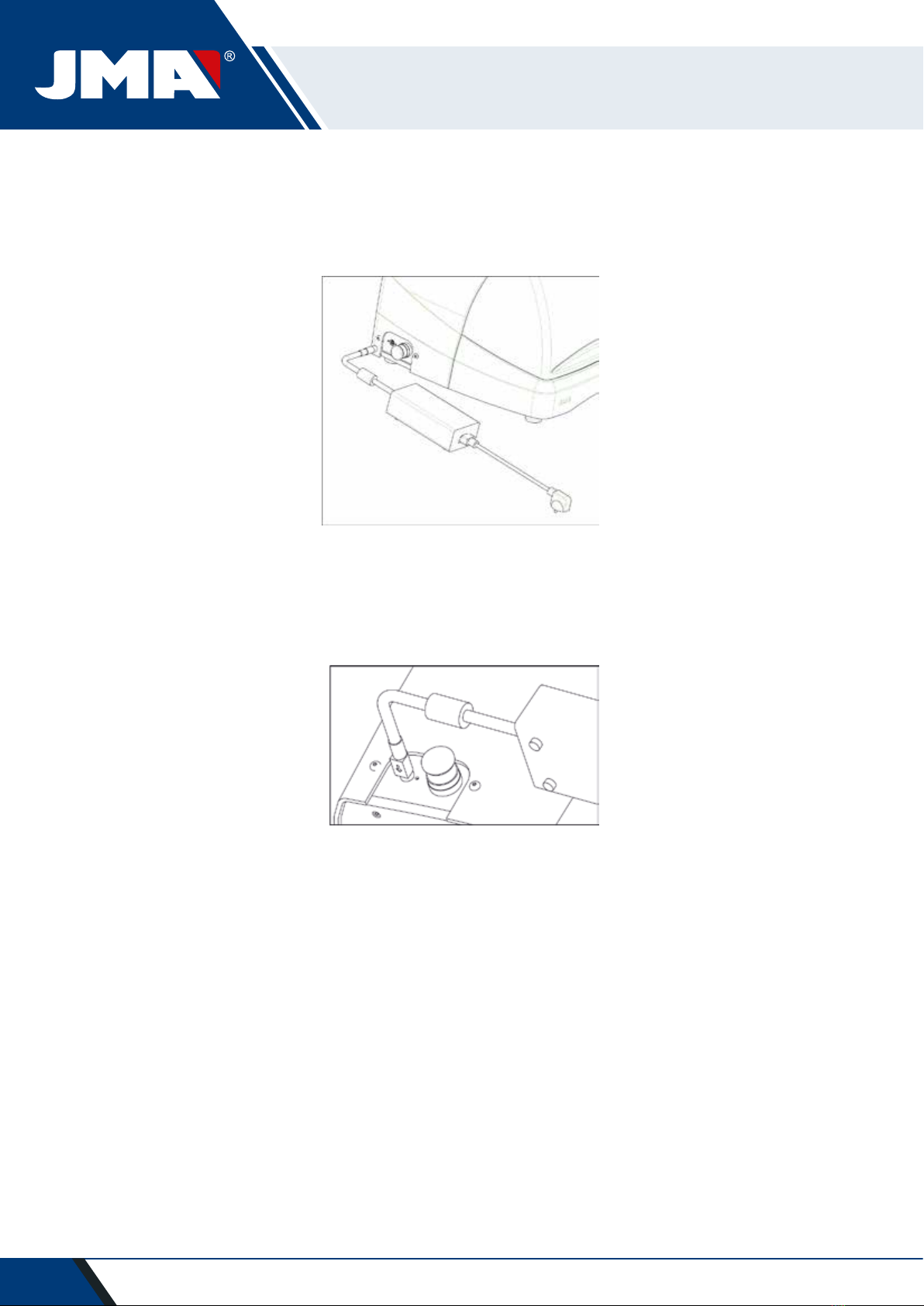
2.1.3 Power unit and power cable..........................................................................................7
2.2 INSTALLATION........................................................................................................................9
2.3 MACHINE DESCRIPTION.........................................................................................................9
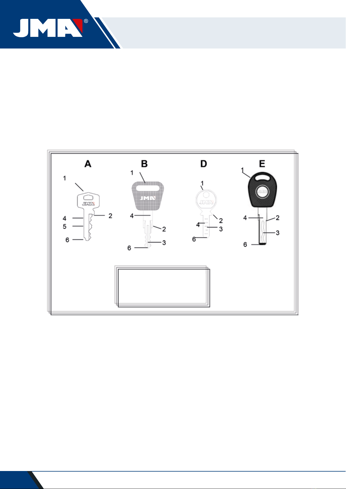
2.4 FAMILY AND TERMINOLOGY OF KEYS. ...............................................................................10
2.5 TECHNICAL DATA .................................................................................................................11
2.6 ACCESSORIES BOX ...............................................................................................................12
3.- JAWS.................................................................................................................................................13
3.1 JAW FOR FLAT KEYS ............................................................................................................13
3.1.1 Use of the standard jaw “MP1” ..................................................................................13
3.2JAW FOR POINTS AND CHANNEL KEYS. .............................................................................15
3.2.1 The jaw. .......................................................................................................................15
3.2.2 Type of limit .................................................................................................................16
3.2.3 Clamp model ................................................................................................................17
3.3 ADJUSTMENT OF DIFFERENT JAWS...................................................................................18
3.3.1 Adjust the jaws, flat keys ............................................................................................18
3.3.2 Adjust safety jaw.........................................................................................................19
4.- USE OF THE TABLET .......................................................................................................................21
4.1 CHARGING AND STARTING THE TABLET ............................................................................21
4.2 CHOOSE LANGUAGE.............................................................................................................21
5.- CLEANING AND SAFETY................................................................................................................23
6.- MAINTENANCE ...............................................................................................................................23
6.1 ACCESS TO THE REAR PART ................................................................................................24
6.2 CONTROL REPLACEMENT.....................................................................................................24
6.3 CLEAN SWARF TRAY AREA..................................................................................................25
6.4 REPLACE PRISMATIC CUTTER. .............................................................................................25
6.5 REPLACEMENT CYLINDRICAL CUTTER ................................................................................26
7.- WASTE ELIMINATION....................................................................................................................27
7.1 PACKAGING ..........................................................................................................................27
7.2 SWARF ..................................................................................................................................27
7.3 MACHINE ..............................................................................................................................27
8.- SERVICE ............................................................................................................................................27
9.- ASSEMBLY DRAWING...................................................................................................................28
10.- SOFTWARE OPERATIONAL GUIDE ............................................................................................29
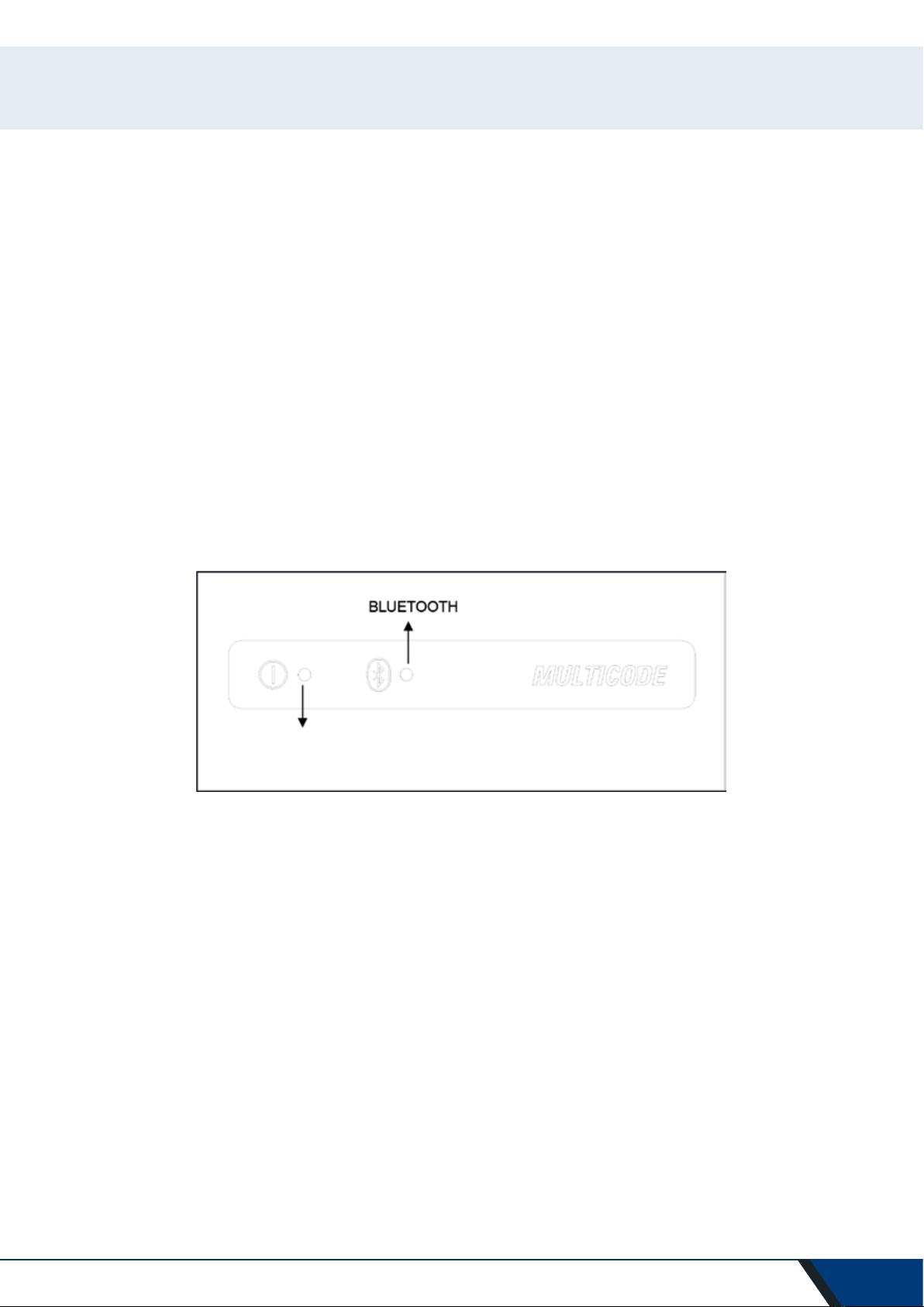
10.1 BLUETOOTH LINK................................................................................................................30
10.2 CHANGE OF LANGUAGE.....................................................................................................32
10.3 KEY SCALE 1:1.....................................................................................................................32
10.4 SEARCHES...........................................................................................................................34
10.4.1 Searches by lock manufacturer (Standard Areas) .....................................................34
10.4.2 Search by automation, by type, by brand, model and year (Automation Area) ........37
10.4.3 Search for keys by equivalents with another manufacturer (Equivalents Area).......38
10.5CUTTING INFORMATION (FILE)............................................................................................39
10.5.1 Toothed key files........................................................................................................39
10.5.2 Point key file ..............................................................................................................43
10.5.3 Channel / Slot key File...............................................................................................46
10.6 JAW SETTINGS...................................................................................................................48
10.6.1 Adjust Toothed Jaw...................................................................................................49
10.6.2 Points/Channel jaw adjustment ................................................................................49
10.7 UPDATE FIRMWARE ...........................................................................................................50
10.8 DIAGNOSTICS .....................................................................................................................52

4
1.- PRESENTATION AND GENERAL ASPECTS
1.1 GENERALITIES
The MULTICODE duplicating machine has been designed taking into account current safety regulations in force in the
E.E.C.
Personal safety involved in the use of this type of machine is only attained with a well designed programme for per-
sonal safety, like the implementation and following of the recommended suggestions as well as compliance with the
safety regulations contemplated in this manual.
Although the installation of the machine is not difficult, we recommend carefully reading this manual before trying to
install, adjust or handle the machine.
The machine has left our factory ready for use and only needs calibrating operations for the tools to be used.
1.2 TRANSPORT AND PACKAGING
The machine is inside a package with the following dimensions:
Width = 610 mm, length = 510 mm, height = 520 mm.
Machine weight plus packaging = 32 Kg.
When unpacking the machine, carefully inspect it to see if it has been damaged during transport. If you discover any
anomaly, immediately notify the transporter and do not do anything with the machine until the transporter agent has
made the corresponding inspection.
1.3 IDENTIFICATION LABEL
The MULTICODE duplicating machine has an identification label (Fig. 1), indicating the serial or registration number of
the machine, name and address of the manufacturer, EC marking and year of manufacturing.
FIG. 1

5
2.- INSTALLATION AND CHARACTERISTICS OF THE MACHINE
2.1 MAIN ELEMENTS OF THE MULTICODE
2.1.1 MULTICODE
FIG. 2
2.1.2 TABLET SUPPORT AND TABLET
The following components are separately packaged in the box of the machine:
• Tablet support and tablet
These two components should be installed on the machine as follows (Fig. 2):

6
1. Unthread the knobs (T1) located on the machine. (Fig. 3)
2. Install the tablet support.
3. Thread and tighten the knob to fix the tablet support on the top part of the machine.
4. Introduce the tablet into the support.
• Use and settings of the tablet support
The tablet support has different settings:
1. Height setting of the upper clamp. Turning the lever (A) clockwise, you can adjust the height of the clamp (B) to
introduce the tablet. After adjustment, block it by turning the lever anticlockwise. Clamps (C) and (D) are adjusted
to adapt to the size of the tablet.
T1
AB
C D
FIG. 4

7
2. Height setting of the tablet support (E) Turning knob (F) anticlockwise, adjusts the height of the tablet clamps.
After adjustment, block knob (F) by turning it clockwise.
3. Turning the tablet support (E). Unblocking the clamp (F), you can turn the tablet support. After setting the posi-
tion, block it again.
F
F
E
FIG. 5
FIG. 6
2.1.3 POWER UNIT AND POWER CABLE

8
Connect the MULTICODE to the power unit (X) and connect this latter to a power outlet using the power cable (X1).
Note: Connect the 24V DC 4 pin connector with the flat face looking downwards.
FIG. 8
FIG. 9

9
2.2 INSTALLATION
The machine is assembled, calibrated and controlled ready for use and does not need any assembly operations. In all
cases, before the first start-up, the following controls should be made:
• Connect the MULTICODE machine to adequate voltage power supply (220V 50Hz or 110V 50/60 Hz) using the su-
pplied power unit (See section 2.1.3)
• It is very important that the electrical installation of the establishment has an earth connection. Make sure that the
machine is connected to earth.
After having unpacked the machine and connected the supplied cable to the power outlet, the machine is ready for
use.
Make sure the emergency button is not pressed, if it is, unblock it.
After starting the machine, the carriages will move to the start position (if they are not there already) and a green light
will show on the display. (Fig. 10)
The MULTICODE machine, will only work if it is connected to the TABLET with the JMAKeyPro program. The commu-
nication between the software and the machine is via Bluetooth.
This said, switch the tablet on and then activate the software. After having activated the program, a blue light will
show on the display. (Fig. 10) The machine is now prepared to operate.
2.3 MACHINE DESCRIPTION
The MULTICODE machine has been designed to cut flat, points/channel type keys. During the design phase, the mi-
nimal details have been analysed to manufacture a compact machine, easy to use and that is very precise. This is a
Mecatronics machine, with three stepper motors for displacement of the carriages.
In other words, we are before a very versatile machine that can be used for both flat, pointed or channel keys.
FIG. 10
OPERATION

10
It reads and/or decodes flat keys with standard coding and point/channel keys using a feeler with electronic contact.
2.4 FAMILY AND TERMINOLOGY OF KEYS
The MULTICODE machine duplicates the following types of keys:
• Flat (A) and vehicle (B) type keys.
• Point (D), channel / groove (vehicles) (E) type keys.
FIG. 11
1.Head
2.Limit
3.Biting
4.Blade
5.Rear
6.Point

11
2.5 TECHNICAL DATA
The main technical data is shown below:
Power supply 24V d.c-7.5 Amp.-180W
Power unit: 100/240V a.c.- 50/60HZ-180W
Cutter Prismatic (Flat keys) High speed steel. Turning speed 1100 rpm
Cutter Cylindrical
(Point/channel or groove keys) Hardened steel. Turning speed 7000 rpm
Standard jaw (MP1) for flat keys With four sides
Jaw for dimple/channel keys With interchangeable jaws
Displacement With flexball (ball screw) activated by stepper motors on
rectified roller guides.
Tool tracks X= 45mm..
Y= 45mm.
Z= 30mm.
Illumination LED diode
Dimensions Depth: 413mm
Width: 427mm
Height with support + tablet: 612mm
Height without support + tablet: 431mm
Tablet Model: Lenovo TB2-X30F
Mass 27Kg.

12
2.6 ACCESSORIES BOX
The MULTICODE machine is equipped with a box for accessories for maintenance and settings (Fig. 12). The acces-
sories are as follows:
FIG. 12
Spanner 18mm Allen Key 2mm Allen Key 5mm
Cutter blocking rod
Ø4x30
Allen Key 2.5mm Fuse: T6.3A 250V
Brush Allen Key in 'T' 3 mm Adjustment lever
CRG
Point limit set Allen key 4mm 03F Cutter
01F Cutter Jaw setting rule RP Jaw rods MP1
of 1.7 and 1.2 mm

13
FIG. 13
3.- JAWS
The machine consists of two jaws, one for machining flat keys and another for point and/or channel keys. The use of
the two jaws for correct operation is detailed below.
3.1 JAW FOR FLAT KEYS
3.1.1 USE OF THE STANDARD JAW “MP1”
The standard jaw “MP1” is designed for reading and machining flat keys. When attaching the key, consider two as-
pects: Side and key limit.
• Sides 1, 2, 3 and 4 of the standard jaw “MP1”.
The different sides and characteristics of the key to be attached are indicated below:
a) Copying a key with rear support.
Side 1: keys with normal blade
Side 2: keys with narrow blade
b) Copying of keys by means attaching the key by its profile
Side 3: Key with guide in lower part
Side 4: Key with guide in upper part
Representation of standard jaw with images of different attaching (Fig. 13)
The standard jaw has 4 sides, (numbers engraved on the top part of the jaw) that
allow closing the attached keys on the rear and profile. The jaw is designed to hold
different models of keys. The side change is simple, leave the jaw slightly open, and
manually turn the key to the desired side.

14
• Key limit.
After having chosen a side of the jaw, then you have to position the key lengthwise, to do that you have to take
into account the limit of the key. Depending on the model of the key, there are two types of limit:
1. Neck limit (C): This is the most common. The key is limited by means of a mechanical limit of the jaw. (Fig. 14)
2. Point limit (1, 2, and 3): The key is limited by means of the pint limit supplied in the accessory box and this is
placed together with the key in the standard jaw slot.
Example of key positions in side 1 and limit 2 (Fig. 15)
FIG. 14
FIG. 15
Point limit

15
Image of a jaw with the numbering of the slots to make the limits. (Fig. 16)
All the necessary information about attaching the key from the JMAKeyPro software in the tablet will appear when
the key code is introduced.
FIG. 16
FIG. 17
3.2 JAW FOR POINTS AND CHANNEL KEYS
According to the key to be machined or coded, follow the indications that appear in the JMAKeyPro software in the
tablet. The main indications refer to the following:
3.2.1 THE JAW
It indicates which model of jaw you should use.
Both point and channel keys can be introduced into the jaw. In the case that the jaw has to be removed, follow
these steps:
1) Raise the transparent guard.
2) Loosen screw (T2) and remove the jaw by moving it toward the operator.
3) Introduce the jaw (previously cleaning the housing) into the dovetail and raise it to the top.
4) Lock the jaw by turning screw (T2).
Side 1: Limits 1, 2, 3.
Side 2: Limits 1, 2.
Side 3: Limits 1, 2.
Side 4: Limits 1, 2.

16
3.2.2 TYPE OF LIMIT
Both point and channel keys can be introduced into the jaw, with neck limit or with point reference. The first (with C
limit) have to be supported against the clamps while the others (point limit) have to be supported with reference in
one of the channels (1-2-3), as indicated in the JMAKeyPro software. For this operation use the point limit that is in
the accessory box, after having positioned the key, remove it.
• Neck limit
• Point limit (1-2-3)
FIG. 18
FIG. 19
Point limit

17
3.2.3 CLAMP MODEL
The jaw has two standard clamps, a fixed one (A) and a mobile one (B). One of the important characteristics of the
clamps is that they have two sides to attach different models of keys. Both the fixed clamp and the mobile one, have
two sides, 1 and 2.
The following steps are to change the clamp or the side of the clamp:
1) Unscrew the knob (T3) to the end
2) Push the clamp(s) with your fingers from its rear part removing it towards the operator. (Fig. 20)
3) Clean the clamp housing area with the brush.
4) Change the clamp of the side and fully introduce it.
Note: The information about the clamps to be used appears in the JMAKeyPro software in the tablet.
FIG. 20

18
3.3 ADJUSTMENT OF DIFFERENT JAWS
The machine has different areas (flat and safety) to adjust the jaws and take readings.
3.3.1 ADJUST THE JAWS, FLAT KEYS
This can be used both for adjusting the cutter or the reader After adjustment, it can be used to take key readings.
The following steps are for adjusting the cutter:
1) Place the CRG (T4) in the jaw MP1 on side 1.(Fig.21)
2) Go to the .SETTINGS menu, select settings→adjust zero-machines (flat key)→Cutter.
3) Select the jaw and then press the cutter adjustment button.
To adjust the reader of flat keys.
1) Place the CRG (T4) in the jaw MP1 on side 1.(Fig.21) (Fig. 22)
2) Place the feeler in the testing position by turning the axis (T5)
FIG. 21
FIG. 22

19
3) Go to the .SETTINGS menu, select settings→adjust zero-machines (flat key)→Reader.
4) Select the jaw and then press the reader adjustment button.
To take readings of flat keys:
1. Place the flat key in the corresponding side of the jaw MP1.
2. Place the feeler in the testing position by turning the axis (T5)
3. In the technical specification of the key, press the key reading button.
3.3.2 ADJUST SAFETY JAW
3.3.2.1 RP FEELER
The RP feeler is used to adjust the cutter, it should be used when changing the jaws or the clamps. Follow these steps:
1) Place the RP feeler on the cutter support (T6)
2) Fix the feeler turning the 3 mm Allen key (T7)
3) Position the RPC adjustment sheet in the clamp.
3) Go to the SETTINGS menu, select settings adjust zero-machines (safety key) Cutter.
4) Select the jaw and then press the cutter adjustment button.
FIG. 23
FIG. 24
T6
T7

20
3.3.2.2 FEELER 1P
The 1P feeler is used to adjust the reader and to code the point or channel keys.
To adjust the reader:
1) Remove the lever (T8) and let it drop to its position.
2) Position the RPC adjustment sheet in the clamp.
3) Go to the SETTINGS menu, select settings adjust zero-machines (safety key) Reader.
4) Select the jaw and then press the cutter adjustment button.
5) After having performed the cycle, return the feeler to its rest position.
To code point or channel keys
1) Remove the lever (T8) and let it drop to its position.
2) In the technical specification of the key, press the key reading button.
FIG. 26
FIG. 25
T8
T
8
Other manuals for MULTICODE
1
Table of contents
Other JMA Industrial Equipment manuals