Tisch Environmental TE-5170DV-BL User manual

OPERATIONS MANUAL
TE-5170DV-BL Total Suspended Particulate
Volumetric Flow Controlled High Volume Air Sampler
Tisch Environmental, Inc.
145 South Miami Avenue
Village of Cleves, Ohio 45002
Toll Free: (877) 263 -7610 (TSP AND-PM10)
Direct: (513) 467-9000
FAX: (513) 467-9009
sales@tisch-env.com
www.tisch-env.com
TE-5170DV-BL 2 Operations Manual
TE-5170DV-BL TSP VFC

TE-5170DV-BL 3 Operations Manual
Welcome
We are the experts in high volume air sampling, lead sampling, lead samplers, particulate monitoring,
particulate emissions, pesticide monitoring, pesticide sampling, total suspended particles, particulate
sampler, Federal Reference Method PM-10, Federal Reference Method PM2.5, EPA Method TO-4A,
EPA Method TO-9A, EPA Method TO-13A. TEI is a family business located in the Village of Cleves,
Ohio. TEI employs skilled personnel who average over 20 years of experience each in the design,
manufacture, and support of air pollution monitoring equipment. Our modern well-equipped factory,
quality philosophy and experience have made TEI the supplier of choice for air pollution monitoring
equipment. Now working on the fourth generation, TEI has state-of-the-art manufacturing capability and
is looking into the future needs of today's environmental professionals.
Assistance
If you encounter problems or require detailed explanations, do not hesitate to
contact Tisch Environmental offices by e-mail or phone.
Toll Free: (877) 263 -7610 (TSP AND-PM10)
Direct: (513) 467-9000
FAX: (513) 467-9009
sales@tisch-env.com
www.Tisch-Env.com

TE-5170DV-BL 4 Operations Manual
Table of Contents
Introduction _______________________________________________________________________ 6
EPA Standards___________________________________________________________________________ 6
Safety Precautions _______________________________________________________________________ 6
Important Safety Instructions ______________________________________________________________ 6
Electrical Installation _____________________________________________________________________ 7
Do Not Abuse Cords ______________________________________________________________________ 7
Extension Cords__________________________________________________________________________ 7
Product Description _________________________________________________________________ 8
Introduction ____________________________________________________________________________ 8
Applications ____________________________________________________________________________ 8
Calibration Requirements__________________________________________________________________ 8
Calibration Kits __________________________________________________________________________ 9
Parts _________________________________________________________________________________ 10
Assembly _________________________________________________________________________ 13
Gabled Roof Assembly ___________________________________________________________________ 14
Electrical Set-Up ________________________________________________________________________ 16
Operations________________________________________________________________________ 17
Calibration Procedure____________________________________________________________________ 17
Example Calculations ____________________________________________________________________ 22
Sampler Operation ______________________________________________________________________ 29
Timer Preparation_______________________________________________________________________ 31
Troubleshooting ___________________________________________________________________ 33
Maintenance and Care ______________________________________________________________ 35
Warranty _________________________________________________________________________ 36
Assembly Drawings_________________________________________________________________ 37

TE-5170DV-BL 5 Operations Manual
TE-5003V Filter Holder ___________________________________________________________________ 37
Calibration Worksheets _____________________________________________________________ 38
Calibration Certificate_______________________________________________________________ 40

TE-5170DV-BL 6 Operations Manual
Introduction
EPA Standards
The following manual will instruct you in the unpacking, assemblage, operation,
calibration, and usage of the corresponding Tisch Environmental product. For
information on air sampling principles, procedures and requirements and to ensure
compliance with government regulations please contact the local Environmental
Protection Agency Office serving your area or visit www.epa.gov.
Safety Precautions
Before using Tisch Environmental products, always be sure to review the
corresponding operations manuals and take all necessary safety precautions. Tisch
Environmental products are to be used only for the purposes specified by
operations manuals and by Tisch Environmental personnel. Tisch Environmental
cannot guarantee the safe usage of its instruments in procedures that do not adhere
to Tisch Environmental guidelines and standards. If you have concerns about the
safety of your product or questions about safe practices, contact Tisch
Environmental by phone or e-mail to speak with a representative.
Important Safety Instructions
Read and understand all instructions. Do not dispose of these instructions. Failure to follow all
instruction listed in this manual may result in electric shock, fire, and/or personal injury. When using an
electrical device, basic precautions must always be followed, including the precautions listed in the
safety section of this manual. Never operate this unit in the presence of flammable materials or vapors
are present as electrical devices may produce arcs or sparks that can cause fire or explosions. Always
disconnect power supply before attempting to service or remove any components. Never immerse
electrical parts in water or any other liquid. Always avoid body contact with grounded surfaces when
plugging or unplugging this device is wet or dangerous conditions.

TE-5170DV-BL 7 Operations Manual
Electrical Installation
Installation must be carried out by specialized personal only, and must adhere to all local safety rules.
This unit can be used for different power supply versions; before connecting this unit to the power line,
always check if the voltage shown on the serial number tag corresponds to the one on your power
supply. This product does use grounded plugs and wires. Grounding provides the path of least resistance
for electrical currents, thereby reducing the risk of electric shock to users. This system is equipped with
electrical cords with internal ground wires and a grounding plug. The plug must be plugged into a
matching outlet that is properly installed and grounded in accordance with all local codes and
ordinances. Do not modify the plug provided. If plug will not fit outlet, have the proper corresponding
outlet installed by a professional, qualified electrician.
Do Not Abuse Cords
In the event that any electrical component of this system needs to be transported, DO NOT carry the
unit by its power cord or unplug the unit by yanking the cord from the outlet. Pull the plugs, not the
cords, to reduce risk of damage to unit. Keep all cords away from heat, oil, sharp objects, and moving
parts.
Extension Cords
It is always advisable to use the shortest extension cord possible. Grounded units require a three-wire
extension cord. As the distance from the supply outlet increases, you must use a heavier gauge extension
cord. Using extension cords with inadequately sized wires results in serious changes in voltage, resulting
in a loss of power and possible damage to equipment. It is recommended to only use 10-gauge extension
cords for this product. Never use cords that exceed one hundred feet. Outdoor extension cords must be
marked with the suffix “W-A” (or “W” in Canada)to indicate that it is suitable for outdoor usage.
Always ensure that extension cords are properly wired and in good electrical condition. Always replace
damaged extension cords immediately, or seek repair from qualified electricians before further use.
Remember to protect extension cords from sharp objects, excessive heat, and damp or wet conditions.

TE-5170DV-BL 8 Operations Manual
Product Description
Introduction
The High Volume Air Sampler (also known as a lead sampler) is the recommended
instrument for sampling large volumes of air for the collection of TSP (Total
Suspended Particulate). The physical design of the sampler is based on aerodynamic
principles that result in the collection of particles of 100 microns (Stokes Equivalent
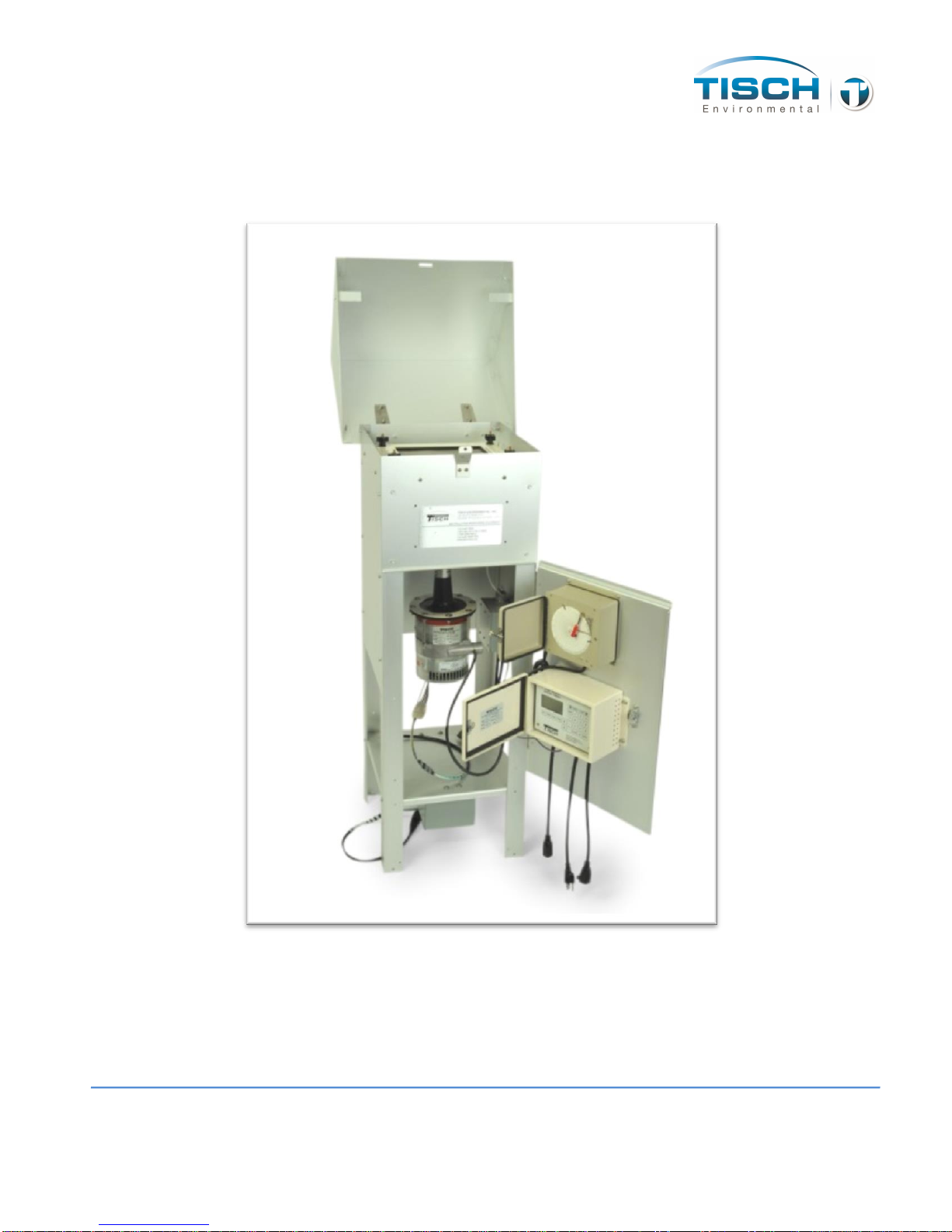
Diameter) and less. The TE-5170DV-BL TSP VFC sampler consists of a TE-5001
Anodized Aluminum Shelter, TE-5001-10 Gabled Roof Assembly, TE-5070-BL
Brushless Blower Motor Assembly, TE-5003V 8”x10” Stainless Steel Filter Holder with
pressure tap, TE-5030 30” Water Manometer, TE-10618 Male Stagnation fitting, TE-
5009 Continuous flow/pressure recorder, TE-10557TSP-BL Volumetric Flow
Controller, and TE-303 Digital Timer/Elapsed Time Indicator(110volt installations
require TE-10965 step up transformer..
Applications
Ambient air monitoring to determine suspended particulate levels relative to air
quality standards.
Impact of a specific source on ambient levels of suspended particulates by
incorporating a "wind-direction-activation" modification which permits the
sampler to operate only when conditions are such that a source-receptor
relationship exists.
Monitoring of enclosed environments for relatively high levels of particulate
matter, particularly toxic materials.
Monitoring of emissions from large diameter vents where physical conditions
preclude the use of conventional stack-testing equipment.
Calibration Requirements
TE-5170DV-BL TSP VFC High Volume Air Sampler should be calibrated:
Upon installation
After any motor maintenance
Once every quarter (three months)
After 360 sampling hours

TE-5170DV-BL 9 Operations Manual
Calibration Kits
The TE-5028 is the calibration kit available for use with the TE-5170DV-BL TSP VFC
High Volume Air Sampler.
The TE-5028 is the preferred method to calibrate the TE-5170DV-BL VFC TSP High
Volume Air Sampler. It simulates change in the resistance by merely rotating the knob
on the top of the calibrator. The infinite resolution lets the technician select the desired
flow resistance. The TE-5028 calibration kit includes: carrying case, 30” slack tube
water manometer, adapter plate, 3’ piece of tubing, and TE-5028A orifice with flow
calibration certificate. Optional electronic manometer is available.
Each TE-5028A is individually calibrated on a primary standard positive displacement
device (Rootsmeter) which is directly traceable to NIST.
** It is recommended by the EPA that each calibrator should be re-calibrated annually. (1998
Code of Federal Regulations Parts 50 to 51, Appendix B to Part 50, Reference Method for the
Determination of Suspended Particulate Matter in the Atmosphere, 9.2.5 page 29.)
TE-5170DV-BL 10 Operations Manual
Parts
1. Shelter Box - 48" x 20" x 20" 72 lbs
TSP VFC System with brushless motor and
digital timer
TE-5170DV-BL 110volt, 60hz
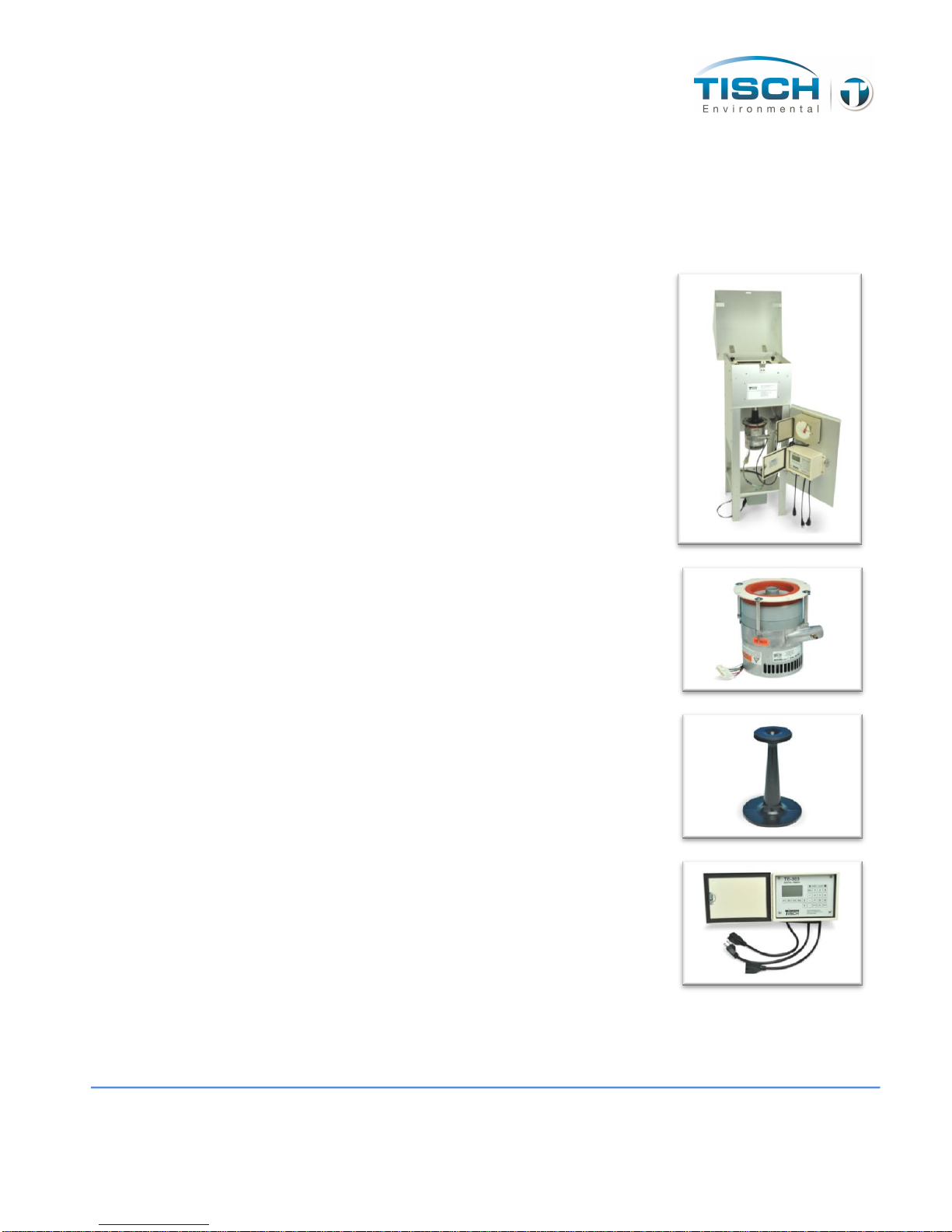
Brushless Blower Motor
TE-5070-BL 110volt and 220volt
Volumetric Flow Controller(attached to
motor)
TE-10557TSP-BL
Digital Timer
TE-303 110volt
TE-5170DV-BL 11 Operations Manual
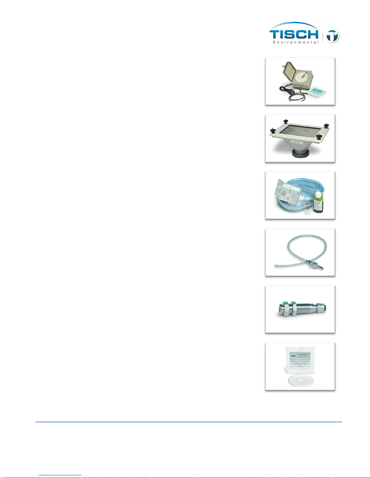
24 Hour Chart recorder
TE-5009 110volt. 60hz
Filter Holder
TE-5003V
30” Water Manometer
TE-5030
Male Stagnation Fitting
TE-10618
Bulkhead Fitting(attached to shelter)
TE-10617
Box of Recorder Charts
TE-106
TE-5170DV-BL 12 Operations Manual
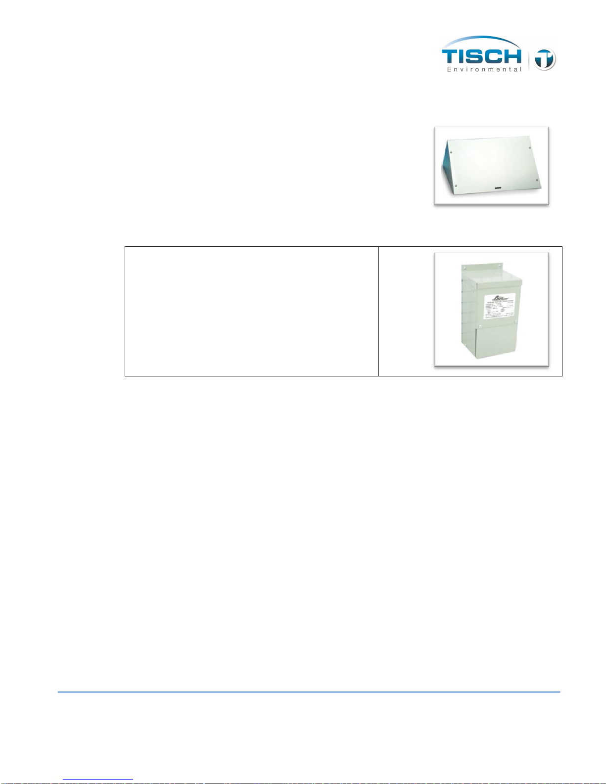
2. Lid Box - 19" x 14" x 14" 9 lbs
Gabled Roof
TE-5001-10
3. Transformer(only for 110volt instalations) 13” x 10” x 9” 30lbs
Step Up Transformer 110volt to 220volt
TE-10965
*** Save the shipping containers and packing material for future use.

TE-5170DV-BL 13 Operations Manual
Assembly
1. Open shelter box and remove Anodized Aluminum Shelter, TE-5003V Filter Holder
with TE-5005-9 gasket, TE-5030 30” Water Manometer, male tube fitting, and TE-
5070-BL VFC Brushless Blower Motor Assembly with VFC attached.
2. Open lid box and remove 5001-10 Roof (for roof assembly see below),
3. Screw TE-5003V Filter Holder onto TE-10557TSP and TE-5070-BL Brushless
Blower Motor Assembly (tubing, power cord, and hole in filter holder collar to the
right) make sure TE-5005-9 gasket is in place.
4. Lower Filter Holder, VFC, and Brushless Blower Motor down through top support
pan on shelter.
5. Connect clear tubing from bulkhead fitting to pressure tap on side of filter holder.
6. Connect black tubing from TE-5070-BL to pressure fitting on the bottom of the TE-
5009 chart recorder.
7. For 110 volt installations only, install power transformer to bottom pan of
shelter using the (4) ¼-20 bolts and nuts supplied with the transformer.
TE-5170DV-BL 14 Operations Manual
Gabled Roof Assembly
The following steps are accompanied by pictures to aid your understanding of gabled
roof assembly. Please be aware that the pictures are standardized and may not
match the equipment that you are using. The gabled roof is used on both TSP and PUF
models, and the assembly procedure is the same for both products.
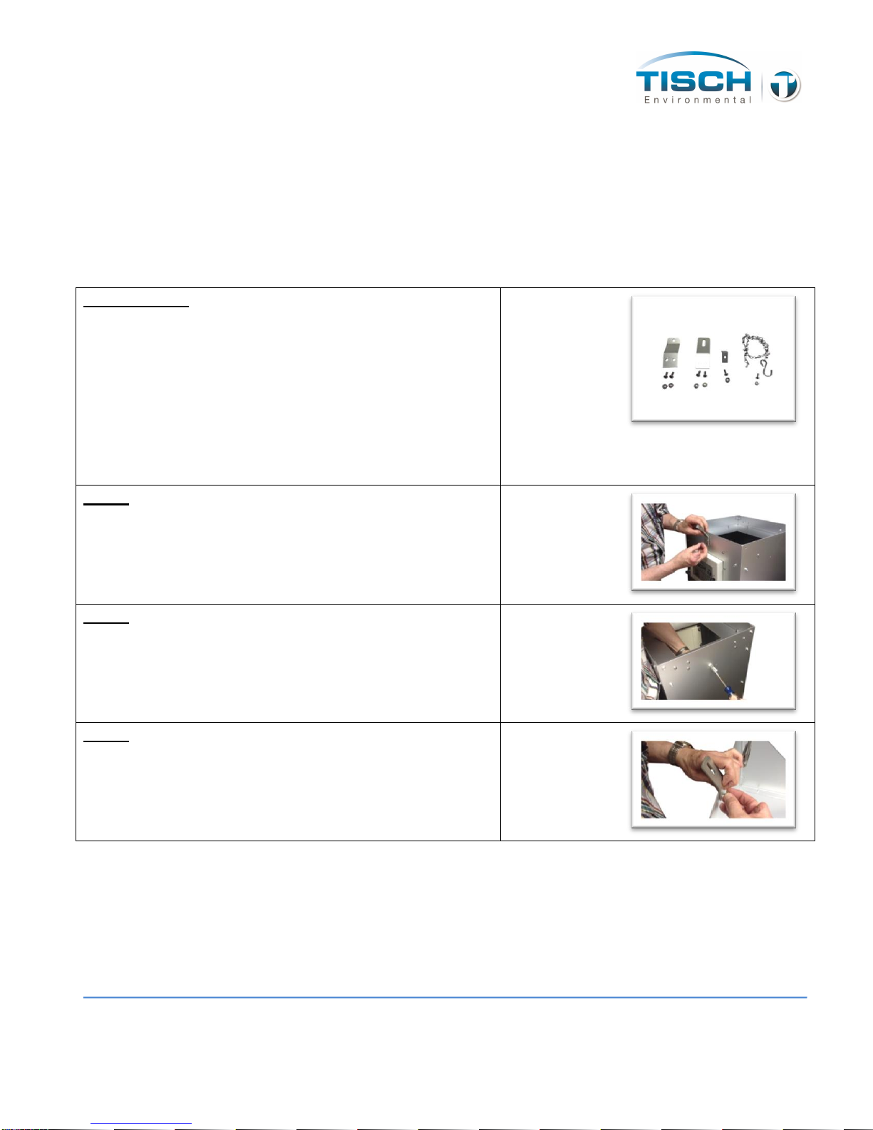
Lid Hardware
5 pcs 10-24 x 1/2 pan head screws
5 pcs 10-24 stop nuts
1 pc 6-32 x 3/8 pan head screw
1 pc 6-32 hex nut
1 pc 20" chain with “S” hook
1 pc TE-5001-10-9 roof back catch
1 pc TE-5001-10-10 front catch
1 pc TE-5001-10-11 rear lid hasp
Step 1
Secure TE-5001-10-10 front catch to the shelter using 2 10-
24 pan head screws with stop nuts. *Do not tighten
completely, this may need to be adjusted after final
assembly*
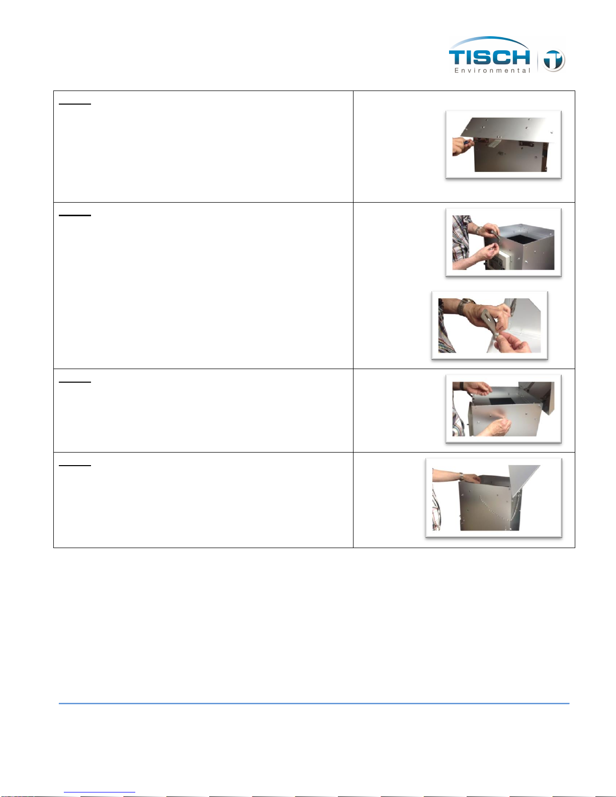
Step 2
Secure TE-5001-10-9 roof back catch to the back of shelter
using #6-32 pan head screw with stop nut.
Step 3
Secure TE-5001-10-11 rear lid hasp inside the lid with the
slot angled up using (2) #10-24 pan head screws with stop
nuts. *Do not tighten completely, this may need to be
adjusted after final assembly*
TE-5170DV-BL 15 Operations Manual
Step 4
Remove (4) #10-24 x ½” pan head screws from the rear of
the shelter, attach the lid to the shelter by placing the lid
hinge plates on the “OUTSIDE” of the shelter, line the
hinges up with the (4) threaded holes in the back of the
shelter. Use the (4) #10-24X ½” pan head screws that were
removed preciously to attach the lid hinges to the shelter.
*Tighten completely*
Step 5
Adjust the front and rears catch to be sure that the lid slots
lowers over it when closing. Tighten the roof back hasp
and front catch completely.
Step 6
Attach the chain and “S” hook assembly to the side of the
shelter with a #6-32 x 3/8” pan head screw.
Step 7
The Lid can now be secured in an open or closed position
with the “S” hook.
TE-5170DV-BL 16 Operations Manual
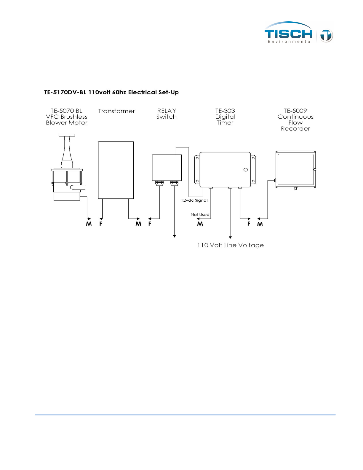
Electrical Set-Up
TE-5170DV-BL 110volt, 60hz
The TE-5070-BL Brushless Blower Motor male cord set plugs into the Transformer
Female cord set.
The Transformer male cord set plugs into the female relay switch cord.
The male cord set on the relay switch is to be plugged into 110 volt line power.
The other female cord set on timer (on the right) is hot all the time and plugs into
the TE-5009 Continuous Flow Recorder male cord set.
The male cord set of timer plugs into the line voltage.

TE-5170DV-BL 17 Operations Manual
Operations
Calibration Procedure
The following is a step by step process of the calibration of a TE-5170V Volumetric Flow Controlled
TSP Particulate Sampling System. Following these steps are example calculations determining the
calibration flow rates for the sampler. The air flow through these types of sampling systems is controlled
by a Volumetric Flow Controller (VFC) or dimensional venturi device.
This calibration differs from that of a mass flow controlled TSP sampler in that a slope and intercept
does not have to be calculated to determine air flows. Also, the calibrator orifice Qactual slope and
intercept from the orifice certification worksheet can be used here, unlike a mass flow controlled TSP
where Qstandard slope and intercept are used. The flows are converted from actual to standard
conditions when the particulate concentrations are calculated. With a Volumetric Flow Controlled
(VFC) sampler, the calibration flow rates are provided in a Flow Look Up Table that accompanies each
sampler.
The attached example calibration worksheet uses a TE-5028A Variable Orifice Calibrator which uses an
adjustable or variable orifice, which we recommend when calibrating a VFC.
Proceed with the following steps to begin the calibration:
Step 1: Mount the calibrator orifice and top loading adapter plate to the sampler. A sampling filter is
generally not used during this procedure. Tighten the top loading adapter hold down nuts securely for
this procedure to assure that no air leaks are present.
Step 2: Turn on the sampler and allow it to warm up to its normal operating temperature.
Step 3: Conduct a leak test by covering the holes on top of the orifice and pressure tap on the orifice
with your hands. Listen for a high-pitched squealing sound made by escaping air. If this sound is heard,
a leak is present and the top loading adapter hold-down nuts need to be re-tightened.
Avoid running the sampler for longer than 30 seconds at a time with the orifice blocked. This will
reduce the chance of the motor overheating. Also, never try this leak test procedure with a manometer

TE-5170DV-BL 18 Operations Manual
connected to the pressure tap on the calibration orifice or the pressure tap on the side of the sampler.
Liquid from either manometer could be drawn into the system and cause motor damage.
Step 4: Connect one side of a water manometer or other type of flow measurement device to the
pressure tap on the side of the orifice with a rubber vacuum tube. Leave the opposite side of the
manometer open to the atmosphere.
Step 5: Connect a water manometer to the quick disconnect located on the side of the aluminum outdoor
shelter (this quick disconnect is connected to the pressure tap on the side of the filter holder).
Step 6: Make sure the TE-5028A orifice is all the way open (turn the black knob counter clock-wise).
Record both manometer readings, the one from the orifice and the other from the side of the sampler. To
read a manometer one side goes up and the other side goes down, you add both sides, this is your inches
of water. Repeat this process for the other four points by adjusting the knob on the variable orifice (just a
slight turn) to four different positions and taking four different readings. You should have five sets of
numbers, ten numbers in all.
Step 7: Remove the variable orifice and the top loading adapter and install a clean filter. Set your timer.
Step 8: Record the ambient air temperature, the ambient barometric pressure, the sampler serial number, the
orifice serial number, the orifice Qactual slope and intercept with date last certified, todays date, site
location and the operators initials.
One example calibration sheet and one blank calibration sheet are attached to this manual. To download
the electronic spreadsheet, please visit www.tisch-env.com (download the TE-5170V High Vol TSP
VFC with G-Factor excel spreadsheet). It is highly recommended to download the electronic excel
spreadsheet and use spreadsheet features to complete calculations. (If you do not have a G Factor then
go to “TE-5170V High Vol. TSP” excel spreadsheet on web site and then go to page 22)
G-Factor Excel Spreadsheet Instructions
The TE-5170V calibration worksheet can be found on our website at www.tisch-
env.com. If you have the G Factor that accompanies each VFC, go to “TE-5170V High
Vol. TSP VFC with G-Factor”, if you do not have a G Factor then go to “TE-5170V High
Vol. TSP” excel spreadsheet.

TE-5170DV-BL 19 Operations Manual
Note: Calibration orifices should be sent back to Tisch Environmental for calibration on
an annual basis per US EPA Compendium Method IO-2.1 Part 7.3.2 Sampling of Ambient
Air For Total Suspened Particulate Matter (SPM) and PM10 Using High Volume (HV)
Sampler
1. Enter the following information in the corresponding cells in the worksheet:
Site Information
Location
The location of the instrument
Date
Current Date
Tech
Technician performing the calibration
Serial #
Serial number of the instrument, Pxxxx
VFC G
Factor
The g-factor of the VFC you are calibrating. This can be found on the
lookup table documentation (first page of this doc) or the sticker
located on the VFC.
Calibration Orifice Information
Make
The make of the orifice, typically Tisch Environmental
Model
The model number of the orifice, typically TE-5028A
Serial #
The Serial number of the calibration orifice you are using
Qa Slope
(m)
The Qa slope of the calibration orifice you are using. This is found
on the calibration documentation provided with the calibration
orifice
Qa Int (b)
The Qa intercept of the calibration orifice you are using. This is
found on the calibration documentation provided with the
calibration orifice
Calibration
Due Date
The date that the calibration of the orifice is due. Orifices should
be calibrated on an annual basis. Call Tisch Environmental at 1-
TSP-AND-PM10 to schedule a calibration.
Ambient Conditions
Temp (Deg
Enter the current ambient temperature at calibration, Ta in

TE-5170DV-BL 20 Operations Manual
F)
Degrees K and Ta in degrees C will be calculated by the
spreadsheet
Barometric
Pressure
Enter the ambient barometric pressure (Pa) inches of Hg at
calibration, the Pa in mmHg will be calculated by the
spreadsheet
2. Enter the calibration information by performing each calibration point and
entering the following information into each corresponding row for each
point:
Calibration Information
Orifice
“H20
The pressure measured at the orifice port using a manometer. The first point should
be performed with the orifice knob turned counter-clockwise or wide open, then four
consecutive points turning the orifice knob clockwise (not closed)
Good idea to take a few extra points here.
Sampler
“H20
The pressure measured at the sampler side port using a manometer
(clear tubing that is connect to bulk head fitting that is connected to
side of filter holder)
The calibrator flow is calculated (Qa) using the formula:
The calculated flow in m3/min will be calculated using the g-factor formula, this flow will correspond to the flow
found in the lookup table supplied with the VFC.
The percent difference will be calculated using the formula:
As per stated in the method IO-2.1, % Difference calculations should be less than +-4%
3. To calculate the total air volume during the sample enter the following
information:
This manual suits for next models
1
Table of contents
Other Tisch Environmental Industrial Equipment manuals


